Advertisement
Advertisement
Table of Contents

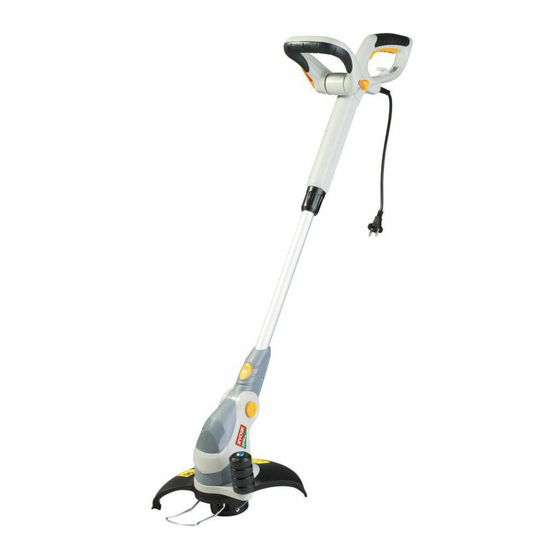
Summary of Contents for Ryobi RLT-710
- Page 1 RLT-710 6986679 (STD) 02-13...
- Page 3 SAFETY ALERT SYMBOL Indicates danger, caution or warning. May be used in conjunction with other symbols or pictures.
- Page 7 description 1. Rear handle 15. Auxiliary handle locking lever 2. Trigger switch 16. Auxiliary handle 3. Cable strain relief 17. Cutting head cover 4. Power cord 18. Release latch for cutting head cover 5. Locking sleeve for length adjustment 19. Safety guard 6.
- Page 8 prepArAtion Warning! Do not connect the machine to the mains socket before it is completely assembled. FittinG GUArd 1. Align the edging support wheel (10) with the safety guard (19) (Fig. 1) Fig. 2 Fig. 3 Fig. 1 2. Secure the edging support wheel and the safety guard with the screws (22) (Fig. 2). 3.
- Page 9 prepArAtion 4. Insert in the auxiliary handle fixing bolt and tighten clockwise by hand (Fig. 7, 8) 5. Adjust the auxiliary handle to required position (Fig. 9, 10, 11) Fig. 9 Fig. 10 Fig. 11 6. Tighten the auxiliary handle fixing bolt clockwise and clamp the auxiliary handle locking lever in upper posi- tion to fix the auxiliary handle in place (Fig.
-
Page 10: Adjusting Trimmer Head Angle
prepArAtion AdJUstinG triMMer HeAd AnGLe Adjust the angle of the trimmer head (11) according to the intended operation. 1. Press the unlock button for trimmer head angle adjustment (7) and hold it in position. 2. Adjust to desired position: Adjust to 0° when trimming grass on the flat ground (Fig. 15). Adjust to 90°... - Page 11 prepArAtion 3. Ensure that the unlock button for pivot head adjustment snaps in place. UsinG edGe GUide Use the edge guide (12) to keep distance to obstacles that could be hit by the cutting device. 1. Adjust the edge guide in lower position for trimming operation (Fig. 19). 2.
-
Page 12: Operation
operAtion cAUtion: Always wear eye protection. stArtinG And stoppinG (Fig. 22) 1. Squeeze the trigger switch (2) to start the trimmer. 2. Release the trigger switch to stop the trimmer. (Fig. 22) Fig. 22 triMMinG 1. Use the trimmer at an angle of approximately 15-degree to the working area (Fig.23). 2. -
Page 13: Replacing Line Spool
operAtion Line FeedinG (Fig. 27) During use, the tip of the trimming line will get shorter due to wear. Regularly check the condition of the trimming line (21) and adjust if necessary. 1. Each time the trimmer reaches a certain speed the line will extend by 12 mm. 2. -
Page 14: Maintenance
8. There are no user serviceable parts in the trimmer. If a fault is suspected return the trimmer to an authorized dealer for repair. IMPORTANT : To assure product safety and reliability, repairs, maintenance and adjustment should be performed by RYOBI authorized service centers or other qualified service organization, always using identical replacement parts. troUBLesHootinG 1. - Page 15 notes...
-
Page 16: Warranty
RYOBI tool (hereinafter called “the Product”), for which it was not designed, or is not suited is warranted by Ryobi (herein called “the and no repairs, alterations or modifications Company”) to be free from defects in material...


