Bosch Rexroth IndraControl VEH 30.1 Project Planning Manual
Hide thumbs
Also See for Rexroth IndraControl VEH 30.1:
- Project planning manual (96 pages) ,
- Project planning manual (76 pages)

Related Manuals for Bosch Rexroth IndraControl VEH 30.1


Summary of Contents for Bosch Rexroth IndraControl VEH 30.1
- Page 1 Electric Drives Linear Motion and and Controls Hydraulics Assembly Technologies Pneumatics Service Rexroth IndraControl VEH 30.1 R911318643 Edition 02 Project Planning Manual...
- Page 2 About this Documentation IndraControl VEH 30.1 Rexroth IndraControl VEH 30.1 Title Project Planning Manual Type of Documentation DOK-SUPPL*-VEH*30.1***-PR02-EN-P Document Typecode Document Number, 120-2100-B389-02/EN Internal File Reference This documentation describes embedded terminals Purpose of Documentation IndraControl VEH 30.1. Record of Revisions...
-
Page 3: Table Of Contents
IndraControl VEH 30.1 Contents Contents System Presentation Brief Description ........................... 1-1 Keypad............................. 1-1 Touch Screen .......................... 1-1 Front View of the IndraControl VEH 30.1 ................1-2 Front View of the IndraControl VAC 30.1 ................1-3 Operating System ......................... 1-3 Commissioning ..........................1-4 Important Directions for Use Appropriate Use.......................... - Page 4 Contents IndraControl VEH 30.1 Used Standards ..........................4-5 4.10 Wear Parts ............................ 4-6 4.11 Compatibility Test ......................... 4-6 Dimensions Housing Dimensions of the IndraControl VEH 30.1 ..............5-1 Housing and Mounting Dimensions of the IndraControl VAC 30.1 ..........5-2 Dimensions of the Wall Holder for the IndraControl VEH 30.1............. 5-3 Display and Operating Components Operating Elements ........................
- Page 5 IndraControl VEH 30.1 Contents Web Server..........................9-10 Telnet Server ......................... 9-10 CE User Configuration......................9-10 WinStudio............................ 9-11 Evaluation of the Operating Element Commands ..............9-12 Evaluation of the Operating Status in the Control ..............9-13 Evaluation of the Keys in the Operating System ..............9-14 System Update ...........................
- Page 6 Contents IndraControl VEH 30.1 DOK-SUPPL*-VEH*30.1***-PR02-EN-P...
-
Page 7: System Presentation
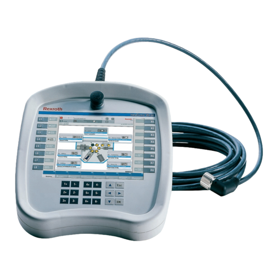
IndraControl VEH 30.1 System Presentation System Presentation Brief Description The embedded terminal IndraControl VEH 30.1 is a portable, powerful, PC-based operator and visualization terminal. The 2-circuit, 3-stage enabling device as well as the 2-circuit STOP pushbutton ensure a safe operation of the controls IndraLogic and IndraMotion. It permits the comfortable configuration of machines and installations located at widely distributed connection points. -
Page 8: Front View Of The Indracontrol Veh 30.1
System Presentation IndraControl VEH 30.1 Front View of the IndraControl VEH 30.1 IndraControl VEH 30.1 with Touch Screen and Keypad Fig. 1-2: Front view of the IndraControl VEH 30.1 DOK-SUPPL*-VEH*30.1***-PR02-EN-P... -
Page 9: Front View Of The Indracontrol Vac 30.1
IndraControl VEH 30.1 System Presentation Front View of the IndraControl VAC 30.1 The hand-held terminal IndraControl VEH 30.1 is connected with the control via the connection module IndraControl VAC 30.1. At the rear side you will find all interfaces to wire the connection module firmly with the control. -
Page 10: Commissioning
System Presentation IndraControl VEH 30.1 Commissioning Please mount the IndraControl VAC 30.1 connection module according to the specifications in chapter "Dimensions". Then, connect the connection module to the voltage supply, the STOP circuit, the enabling circuit and the network. Before commissioning the IndraControl VEH 30.1 the operator has to assure that the installation, especially the safety devices, are in a proper status. - Page 11 IndraControl VEH 30.1 System Presentation Note: While the connector is screwed on, a relay activates the STOP pushbutton. Thus, the IndraControl VEH 30.1 is supplied with voltage. Screw the knurled nut as far as the rubber seal is completely covered and the end position is reached to ensure the optimal connection of the contacts and to achieve the specified degree of protection.
- Page 12 System Presentation IndraControl VEH 30.1 DOK-SUPPL*-VEH*30.1***-PR02-EN-P...
-
Page 13: Important Directions For Use
Note: Bosch Rexroth, as manufacturer, is not liable for any damages resulting from inappropriate use. In such cases, the guarantee and the right to payment of damages resulting from inappropriate use are forfeited. -
Page 14: Areas Of Use And Application
This includes, for example, operation under water, in the case of extreme temperature fluctuations or extremely high maximum temperatures, or if • Bosch Rexroth has not specifically released them for that intended purpose. Please note the specifications outlined in the general Safety Guidelines! DOK-SUPPL*-VEH*30.1***-PR02-EN-P... -
Page 15: Safety Instructions For Electric Drives And Controls
If you do not have the user documentation for your equipment, contact your local Bosch Rexroth representative to send this documentation immediately to the person or persons responsible for the safe operation of this equipment. -
Page 16: Hazards By Improper Use
Safety Instructions for Electric Drives and Controls IndraControl VEH 30.1 Hazards by Improper Use High voltage and high discharge current! Danger to life or severe bodily harm by electric shock! DANGER Dangerous movements! Danger to life, severe bodily harm or material damage by unintentional motor movements! DANGER High electrical voltage due to wrong... -
Page 17: General Information
IndraControl VEH 30.1 Safety Instructions for Electric Drives and Controls General Information • Bosch Rexroth AG is not liable for damages resulting from failure to observe the warnings provided in this documentation. • Read the operating, maintenance and safety instructions in your language before starting up the machine. -
Page 18: Protection Against Contact With Electrical Parts
Safety Instructions for Electric Drives and Controls IndraControl VEH 30.1 • Operation is only permitted if the national EMC regulations for the application are met. The instructions for installation in accordance with EMC requirements can be found in the documentation "EMC in Drive and Control Systems". -
Page 19: Protection Against Electric Shock By Protective Low Voltage (Pelv)
IndraControl VEH 30.1 Safety Instructions for Electric Drives and Controls To be observed with electrical drive and filter components: High electrical voltage on the housing! High leakage current! Danger to life, danger of injury by electric shock! ⇒ Connect the electrical equipment, the housings of all DANGER electrical units and motors permanently with the safety conductor at the ground points before power is... -
Page 20: Protection Against Dangerous Movements
Safety Instructions for Electric Drives and Controls IndraControl VEH 30.1 Protection Against Dangerous Movements Dangerous movements can be caused by faulty control of the connected motors. Some common examples are: • improper or wrong wiring of cable connections • incorrect operation of the equipment components •... -
Page 21: Protection Against Magnetic And Electromagnetic Fields During Operation And Mounting
IndraControl VEH 30.1 Safety Instructions for Electric Drives and Controls ⇒ Secure vertical axes against falling or dropping after switching off the motor power by, for example: - mechanically securing the vertical axes - adding an external braking/ arrester/ clamping mechanism - ensuring sufficient equilibration of the vertical axes The standard equipment motor brake or an external... -
Page 22: Protection Against Contact With Hot Parts
Safety Instructions for Electric Drives and Controls IndraControl VEH 30.1 Protection Against Contact with Hot Parts Housing surfaces could be extremely hot! Danger of injury! Danger of burns! ⇒ Do not touch housing surfaces near sources of heat! Danger of burns! CAUTION After switching the equipment off, wait at least ten (10) ⇒... -
Page 23: 3.11 Battery Safety
IndraControl VEH 30.1 Safety Instructions for Electric Drives and Controls 3.11 Battery Safety Batteries contain reactive chemicals in a solid housing. Inappropriate handling may result in injuries or material damage. Risk of injury by incorrect handling! ⇒ Do not attempt to reactivate discharged batteries by heating or other methods (danger of explosion and cauterization). - Page 24 3-10 Safety Instructions for Electric Drives and Controls IndraControl VEH 30.1 Notes DOK-SUPPL*-VEH*30.1***-PR02-EN-P...
-
Page 25: Technical Data
IndraControl VEH 30.1 Technical Data Technical Data IndraControl VEH 30.1 NS-Geode 300 MHz and integrated graphic controller with 4 MB shared memory Processor Working memory 128 MB 128 MB Compact flash card 1 x Ethernet connection (RJ 45, 10/100 Base-T) Interfaces •... -
Page 26: Enabling Device
Technical Data IndraControl VEH 30.1 Enabling Device Design 3-stage enabling switch*, 2-channel, electrically isolated 24-VDC-/30-VAC safety extra-low voltage Nominal voltage 2 A= / 2,3 A~ current carrying capacity of the output contacts is limited by Nominal current* the connected cable 2-A-fusible cut-out, time-lag Prescribed external protection >200,000 for the enabling range, >100,000 for the panic position... -
Page 27: Ambient Conditions
IndraControl VEH 30.1 Technical Data Ambient Conditions In operation Storage Transport +5 °C to 40 °C -20 °C to +60 °C -20 °C to +60 °C Max. surrounding air according to EN 50178 temperature Max. temperature Temporal temperature Temporal temperature Temporal temperature changes up to 3 K per minute changes up to 3 K per minute... -
Page 28: Identification
Technical Data IndraControl VEH 30.1 Identification Identify the device with the name plate on the rear side of the device. Fig. 4-7: Name plate of the IndraControl VEH 30.1 1. Company logo / Technical data 2. Ordering designation / short type 3. -
Page 29: Used Standards
IndraControl VEH 30.1 Technical Data Used Standards system components embedded terminal IndraControl VEH 30.1 correspond to the following standards: Standard Meaning EN 50178 Equipment for use in power installations EN 60 204-1 Electrical equipment of machines EN 50 081-2 Basic technical standard, emitted interference (industrial environment) EN 50 082-2 Basic technical standard, noise immunity (industrial... -
Page 30: 4.10 Wear Parts
(e.g. lubricants in machine tools) which may interact with our controls and drives, it cannot be completely ruled out that any reactions with the materials used by Bosch Rexroth might occur. For this reason, before using the respective material a compatibility test has to be carried out for new lubricants, cleaning agents etc. -
Page 31: Dimensions
IndraControl VEH 30.1 Dimensions Dimensions Housing Dimensions of the IndraControl VEH 30.1 The width of the IndraControl VEH 30.1 is 270 mm and the height is 290.54 mm. Fig. 5-1: Front view of the IndraControl VEH 30.1 DOK-SUPPL*-VEH*30.1***-PR02-EN-P... -
Page 32: Housing And Mounting Dimensions Of The Indracontrol Vac 30.1
Dimensions IndraControl VEH 30.1 Housing and Mounting Dimensions of the IndraControl VAC 30.1 X1.1 X1.2 X2.1 X2.2 Fig. 5-2: Housing and mounting dimensions of the IndraControl VAC 30.1 DOK-SUPPL*-VEH*30.1***-PR02-EN-P... -
Page 33: Dimensions Of The Wall Holder For The Indracontrol Veh 30.1
IndraControl VEH 30.1 Dimensions Dimensions of the Wall Holder for the IndraControl VEH 30.1 -0.1 64.5 -0.1 60.7 72.2 134.2 Fig. 5-3: Dimensions of the wall holder for the IndraControl VEH 30.1 DOK-SUPPL*-VEH*30.1***-PR02-EN-P... - Page 34 Dimensions IndraControl VEH 30.1 DOK-SUPPL*-VEH*30.1***-PR02-EN-P...
-
Page 35: Display And Operating Components
IndraControl VEH 30.1 Display and Operating Components Display and Operating Components Operating Elements Information on almost all operating elements are transmitted to the control in form of a real time protocol and are available via a function block. For further information please refer to chapter "Evaluation of Operating Element Commands"... -
Page 36: Fig. 6-3: Handling Of The Indracontrol Veh 30.1
Display and Operating Components IndraControl VEH 30.1 Fig. 6-2: Rear view of the IndraControl VEH 30.1 The enabling switch as well as the two actuators are integrated in the bottom part of the housing. The housing geometry supports the carrying of the housing. - Page 37 IndraControl VEH 30.1 Display and Operating Components Fig. 6-3: Handling of the IndraControl VEH 30.1 The ergonomic housing shape and the molded handles support several types of using: Hand-held: As described above, the IndraControl VEH 30.1 lying on the forearm can be supported against the body.
-
Page 38: Keypad
Display and Operating Components IndraControl VEH 30.1 Keypad Position of the Keys of the IndraControl VEH 30.1 Fig. 6-4: Position of the keys of the IndraControl VEH 30.1 Operation keys L1-L8 and R1-R8 The assignment of the operation keys is fixed. The evaluation is specified by the respective application software. -
Page 39: Safety Operating Components
IndraControl VEH 30.1 Display and Operating Components Safety Operating Components Safety Concept The IndraControl VEH 30.1 is provided with a 2-circuit, 3-stage enabling switch operated by two actuators integrated in the housing. It consists of single switching elements and can be used in safety circuits up to category 4 (EN 954-1), if the evaluation is appropriate. -
Page 40: Fig. 1-1: Indracontrol Veh 30.1
Display and Operating Components IndraControl VEH 30.1 STOP Pushbutton The IndraControl VAC 30.1 is equipped with an automatic STOP circuit jumpering. Thus, the operator can connect or disconnect the hand-held terminal IndraControl VEH 30.1 connection module IndraControl VAC 30.1 without causing an unintended stopping of the installation. -
Page 41: Fig. 6-6: Time Course When Connecting The Indracontrol Veh 30.1 Stop Circuit
IndraControl VEH 30.1 Display and Operating Components If the 17-pin connector is completely screwed on the connection module, relay K1 switches and supplies the IndraControl VEH 30.1 with voltage via NO contact K1.3. Simultaneously, by opening contacts K1.1 and K1.2 the STOP circuit jumpering is deactivated. -
Page 42: Optional Operating Elements
Display and Operating Components IndraControl VEH 30.1 Optional Operating Elements Additional Components The following additional elements to operate controls are available: Left side Right side Override Handwheel Fig. 6-7: Additional elements of the IndraControl VEH 30.1 Override The IndraControl VEH 30.1 can optionally be ordered with an override switch. -
Page 43: Interfaces Of The Indracontrol Veh 30.1
IndraControl VEH 30.1 Interfaces of the IndraControl VEH 30.1 Interfaces of the IndraControl VEH 30.1 Connection of the IndraControl VEH 30.1 via the IndraControl VAC 30.1 The IndraControl VEH 30.1 is connected via the connection module IndraControl VAC 30.1. Pin Assignment of the IndraControl VAC 30.1 Fig. -
Page 44: X1: 24 Vdc Voltage Supply
Interfaces of the IndraControl VEH 30.1 IndraControl VEH 30.1 Note: Use only copper wire to connect these terminals. Tighten the screws of the screw terminals with a torque of 0.22 Nm. X1: 24 VDC Voltage Supply All internally required voltages are generated with electrical isolation via a DC/DC converter. -
Page 45: Fig. 7-5: Safety Transformer According To En 60742
IndraControl VEH 30.1 Interfaces of the IndraControl VEH 30.1 400V + 5% 400V 400V - 5% + 24V Fig. 7-5: Safety transformer according to EN 60742 Interfering AC voltage components such as resulting from an uncontrolled 3-phase current bridge connection without smoothing with a ripple factor (see DIN 40110/10.75, section 1.2) of 5 % are permissible. -
Page 46: X2.1: Stop Pushbutton
Interfaces of the IndraControl VEH 30.1 IndraControl VEH 30.1 (green/yellow) Power supply with safety transformer acc. to EN 60742 24 VDC Cross-sections depending on current consumption, min. of 4 mm . For higher current con- sumption use 2 x 4 mm . (blue) Length max. -
Page 47: X2.2: Enabling Device
IndraControl VEH 30.1 Interfaces of the IndraControl VEH 30.1 X2.2: Enabling Device Pin Assignment Signal name X2.2 Pin1 Enabling device 1 IN X2.2 Pin2 Enabling device 1 OUT X2.2 Pin3 Enabling device 2 IN X2.2 Pin4 Enabling device 2 OUT Fig. -
Page 48: Fig. 7-11: Contact Travel Diagram
Interfaces of the IndraControl VEH 30.1 IndraControl VEH 30.1 Contact Travel Diagram of the Enabling Switch S1.1 S1.2 S2.1 S2.2 S1.1 S1.2 Richtung a Direction a S2.1 S2.2 S1.1 S1.2 Direction b Richtung b S2.1 S2.2 Fig. 7-11: Contact travel diagram DOK-SUPPL*-VEH*30.1***-PR02-EN-P... - Page 49 IndraControl VEH 30.1 Interfaces of the IndraControl VEH 30.1 Wiring of the Enabling Switch The following special requirements apply for the connection between the IndraControl VEH 30.1 and the safety-related evaluation for the enabling switch: It is required that short-circuits and/or cross-circuits on the safety- related signal paths are safely detected by evaluation devices.
-
Page 50: Fig. 7-12: Internal Wiring: Category
Interfaces of the IndraControl VEH 30.1 IndraControl VEH 30.1 If the 2-circuit enabling switch is wired in the IndraControl VEH 30.1 Category 2 (EN 954-1) according to category 1 and is completed by an automatic (not necessarily safety-relevant) test, category 2 can be achieved. Fig. -
Page 51: Fig. 7-14: Internal Wiring: Category
IndraControl VEH 30.1 Interfaces of the IndraControl VEH 30.1 If the CH-3000 shall be used in control category 3 or 4, it has to be wired Category 3/4 (EN 954-1) with an appropriate monitoring module also recognizing short- and cross- circuits in the line. -
Page 52: X3: Ethernet Interface
7-10 Interfaces of the IndraControl VEH 30.1 IndraControl VEH 30.1 X3: Ethernet Interface The embedded terminal can be connected with an Ethernet network via an Ethernet interface. RJ45 female connector, 8-pin Type: Ethernet 10Base T / 100Base X Cable length: Max. -
Page 53: Personality Function
7-11 IndraControl VEH 30.1 Interfaces of the IndraControl VEH 30.1 Personality Function In the majority of cases, the system features a continuous Ethernet network. However, e. g. M-Keys, STOP pushbuttons or enabling devices are firmly assigned to one control. The IndraControl VAC 30.1 provides that an individual IP address and corresponding target addresses of the control are allocated to a hand-held terminal. - Page 54 7-12 Interfaces of the IndraControl VEH 30.1 IndraControl VEH 30.1 DOK-SUPPL*-VEH*30.1***-PR02-EN-P...
-
Page 55: Maintenance And Installation
A fading backlight causes a progressive deterioration of the LCD display's readability, so that a backlight exchange will be necessary. For further information please contact the Bosch Rexroth Service. Maintenance of the IndraControl VEH 30.1 The IndraControl VEH 30.1 is designed for the use in the industrial environment. -
Page 56: Measures In Case Of Malfunctions At The Indracontrol Veh 30.1
Maintenance and Installation IndraControl VEH 30.1 Measures in Case of Malfunctions at the IndraControl VEH 30.1 The IndraControl VEH 30.1 does not contain any components to be maintained by the operator. The housing must not be opened for maintenance purposes. Malfunctions that are not mentioned in the following table require a check of the device at the manufacturer. -
Page 57: Software
IndraControl VEH 30.1 Software Software General Information The IndraControl VEH 30.1 is delivered with the embedded operating system Microsoft Windows CE .NET 4.2. The operating system is contained in the FWA and has to be separately ordered besides the IndraControl VEH 30.1. Furthermore, this FWA contains the visualization software WinStudio "lite". -
Page 58: Touch Screen Calibration
Software IndraControl VEH 30.1 Touch Screen Calibration If the position of the mouse pointer does not match anymore with the touched point on the display, the touch can be recalibrated. The calibration program can be started via the desktop icon Touch Calibration or the start menu Start –... -
Page 59: Ethernet Adapter
IndraControl VEH 30.1 Software Ethernet Adapter The Ethernet adapter of the IndraControl VEH 30.1 is configured in this tab. Fig. 9-4: Rexroth CE Settings – Ethernet Adapter Obtain an IP Address via DHCP Automatic assignment of the network parameters via DHCP. Specify an IP Address Manual configuration of the network parameters. -
Page 60: Application Settings
Software IndraControl VEH 30.1 Application Settings In this tab the settings for autostart and the visualization connection to the control are configured. Fig. 9-5: Rexroth CE Settings – Application Settings Visualization Data Source • Ethernet: Ethernet connection to the control. •... -
Page 61: Data Server
IndraControl VEH 30.1 Software Visualization • None: The visualization software is not automatically started. • Remote Desktop: Autostart of the Remote Desktop Client. A PC with Remote Desktop Server in the network is operated by remote control via the IndraControl VEH 30.1. •... -
Page 62: System Info
Software IndraControl VEH 30.1 start FTP server automatically The autostart of the internal FTP server can be set here. start WEB server automatically The autostart of the internal web server can be set here. start Telnet server automatically The autostart of the internal telnet server can be set here. System Info This tab indicates information on the FWA and the IndraControl hardware. -
Page 63: Windows Ce 4.2 .Net
IndraControl VEH 30.1 Software Windows CE 4.2 .NET Fig. 9-8: Windows CE 4.2 .NET desktop The Windows CE 4.2 .NET operating system image provides various programs and tools. Operation Touch Screen Operation The IndraControl VEH 30.1 is operated via a touch screen. For this, use your finger or better a touch pen. -
Page 64: Fig. 9-9: Selecting The Virtual Keyboard
Software IndraControl VEH 30.1 Fig. 9-9: Selecting the virtual keyboard Fig. 9-10: Virtual keyboard, small Fig. 9-11: Virtual keyboard, large DOK-SUPPL*-VEH*30.1***-PR02-EN-P... -
Page 65: Microsoft Programs
IndraControl VEH 30.1 Software Microsoft Programs The following programs can be either called up by links on the desktop or by the start menu. Microsoft File Viewer • Microsoft Excel Viewer: Program to display table files in *.XL* format. • Microsoft Image Viewer: Program to display image files, slideshows and to generate slideshows. -
Page 66: Ftp Server
9-10 Software IndraControl VEH 30.1 FTP Server The FTP server can be activated or deactivated via the Rexroth CE Settings (see chapter "Rexroth CE Settings"; section "Data Server" on page 9-5). If a user logs in as "Anonymous" at the FTP server, he will get access to directory \FTP_Public on the RAM disk. -
Page 67: Winstudio
9-11 IndraControl VEH 30.1 Software WinStudio The IndraControl VEH 30.1 devices contain runtime visualization software WinStudio "lite". The functional range of the "lite" variant is restricted. If an extended functional range is required, you have to order a license (see chapter 9.1 "General Information"). Variables Arrays Class elements... -
Page 68: Evaluation Of The Operating Element Commands
9-12 Software IndraControl VEH 30.1 Remote Agent Setup Fig. 9-14: Remote Agent Setup • Device Connection: Configuration of the connection. The connection only established TCP/IP. Infra-red serial communication is not supported by the IndraControl VEH 30.1. • Run CEView on startup: Here, you can choose, if the CEView shall be automatically started while starting the system. -
Page 69: Evaluation Of The Operating Status In The Control
9-13 IndraControl VEH 30.1 Software Evaluation of the Operating Status in the Control The operating status of the M-Keys, the jog keys, the enabling device and the additional operating elements are transmitted directly into the control by a real time protocol via Ethernet communication. In the control you have the possibility to evaluate the status of the operating elements by means of a function block. -
Page 70: Evaluation Of The Keys In The Operating System
9-14 Software IndraControl VEH 30.1 UDP bit PLC-FB Remark Data[3].0 Enabling switch Panic Panic Data[4].7 Data[4].6 Data[4].5 Data[4].4 Data[4].3 Data[4].2 Data[4].1 Data[4].0 Data[5].7 Data[5].6 Data[5].5 Data[5].4 Data[5].3 Override OvR.3 OvR.3 Data[5].2 Override OvR.2 OvR.2 Data[5].1 Override OvR.1 OvR.1 Data[5].0 Override OvR.0 OvR.0 Data[6].7... -
Page 71: System Update
9-15 IndraControl VEH 30.1 Software Examples: Small letter 'A' KeyStroke='A' Small letter 'A' KeyStroke=0x41 Small letter 'A' KeyStroke=VK_A Capital letter 'A' KeyStroke=VK_SHIFT-'A' Capital letter 'A' KeyStroke=VK_SHIFT-0x41 Capital letter 'A' KeyStroke=VK_SHIFT-VK_A Ctrl-Alt-Del KeyStroke=VK_CTRL-VK_ALT-VK_DEL System Update As of operating system version 01V01 of the IndraControl VEH 30.1 an update functionality is provided. -
Page 72: Upload Via Ftp Server
9-16 Software IndraControl VEH 30.1 Upload via FTP Server As next step, establish an FTP connection from an upload computer containing the complete file structure of the new operating system to the IndraControl VEH 30.1. Use a graphic explorer of the upload computer as FTP client. -
Page 73: Ordering Information
10-1 IndraControl VEH 30.1 Ordering Information Ordering Information 10.1 Type Code The embedded terminal IndraControl VEH 30.1 has the following features according to the type code illustrated below: IndraControl VEH 30.1 Abbrev. Column 1 2 3 4 6 7 8 9 1 2 3 4 6 7 8 9 1 2 3 4... -
Page 74: Indracontrol Vac 30.1
10-2 Ordering Information IndraControl VEH 30.1 IndraControl VAC 30.1 Abbrev. Column 1 2 3 4 6 7 8 9 1 2 3 4 6 7 8 9 1 2 3 4 6 7 8 9 1 2 3 4 6 7 8 9 Example: V A C 3 0 . -
Page 75: List Of Figures
11-1 IndraControl VEH 30.1 List of Figures List of Figures Fig. 1-1: IndraControl VEH 30.1 1-1 Fig. 1-2: Front view of the IndraControl VEH 30.1 1-2 Fig. 1-3: Front view of the IndraControl VAC 30.1 1-3 Fig. 1-4: Plug orientation at the IndraControl VAC 30.1 1-4 Fig. - Page 76 11-2 List of Figures IndraControl VEH 30.1 Fig. 7-14: Internal wiring: category 3 7-9 Fig. 7-15: Ethernet interface 7-10 Fig. 7-16: Pin assignment of the Ethernet interface X3 7-10 Fig. 8-1: Error table of the IndraControl VEH 30.1 8-2 Fig. 9-1: Firmware type of the IndraControl VEH 30.1 9-1 Fig.
-
Page 77: Index
12-1 IndraControl VEH 30.1 Index Index Accessories 10-2 Air pressure 4-3 Ambient conditions 4-3 Appropriate use Introduction 2-1 Uses 2-2 Backlight dimming 6-8 Compatibility test 4-6 Dimensions 5-1 Housing and Mounting Dimensions of the IndraControl VAC 30.1 5-2 Housing dimensions of the IndraControl VEH 30.1 5-1 Dimensions of the wall holder for the IndraControl VEH 30.1 5-3 Display and operating components 6-1 Enabling device X2.2 on VAC 30 7-5... - Page 78 12-2 Index IndraControl VEH 30.1 Safety Instructions for Electric Drives and Controls 3-1 Safety transformer according to EN 60742 7-3 STOP pushbutton X2.1 on VAC 30 7-4 System presentation 1-1 Brief description 1-1 Commissioning 1-4 Operating system 1-3 Variants 1-1 Technical data Wear parts 4-6 Technical data 4-1...
-
Page 79: Service & Support
13-1 IndraControl VEH 30.1 Service & Support Service & Support 13.1 Helpdesk Unser Kundendienst-Helpdesk im Hauptwerk Lohr Our service helpdesk at our headquarters in Lohr am am Main steht Ihnen mit Rat und Tat zur Seite. Main, Germany can assist you in all kinds of inquiries. Sie erreichen uns Contact us +49 (0) 9352 40 50 60... -
Page 80: Kundenbetreuungsstellen
Tel.: +49 (0)171 333 88 26 service.svc@boschrexroth.de Vertriebsgebiet Süd Vertriebsgebiet West Gebiet Südwest Germany South Germany West Germany South-West Bosch Rexroth AG Bosch Rexroth AG Bosch Rexroth AG Landshuter Allee 8-10 Regionalzentrum West Service-Regionalzentrum Süd-West 80637 München Borsigstrasse 15 Siemensstr. 1... - Page 81 Netherlands – Niederlande/Holland Netherlands - Niederlande/Holland Norway - Norwegen Tightening & Press-fit: Bosch Rexroth B.V. Bosch Rexroth Services B.V. Bosch Rexroth AS TEMA S.p.A. Automazione Kruisbroeksestraat 1 Technical Services Electric Drives & Controls Via Juker, 28 (P.O. Box 32) Kruisbroeksestraat 1...
- Page 82 - Südafrika South Africa - Südafrika AIMS - Australian Industrial TECTRA Automation (Pty) Ltd. Tightening & Press-fit: Bosch Rexroth Pty. Ltd. Machinery Services Pty. Ltd. 100 Newton Road, Meadowdale Jendamark Automation No. 7, Endeavour Way 28 Westside Drive Edenvale 1609...
- Page 83 S-10, Green Park Extension Building # 202, Cilandak Commercial Service Center Japan Electric Drives & Controls New Delhi – 110016 Estate 2125-1 atsukawado-cho BOSCH Bldg. 4F, 3-6-7 Shibuya Jl. Cilandak KKO, Jakarta 12560 Kasugai-shi Aichi-ken Shibuya-ku, Tokyo 486-0932, Japan 150-0002, Japan Tel.: +91 11 26 56 65 25 Tel.: +62 21 7891169 (5 lines)
- Page 84 Canada West - Kanada West CANADA SERVICE HOTLINE Mexico Mexico Bosch Rexroth Canada Corporation Bosch Rexroth Mexico S.A. de C.V. Bosch Rexroth S.A. de C.V. 5345 Goring St. Calle Neptuno 72 Calle Argentina No 3913 Burnaby, British Columbia Unidad Ind. Vallejo Fracc.
- Page 86 Bosch Rexroth AG Electric Drives and Controls P.O. Box 13 57 97803 Lohr, Germany Bgm.-Dr.-Nebel-Str. 2 97816 Lohr, Germany Phone +49 (0)93 52-40-50 60 +49 (0)93 52-40-49 41 service.svc@boschrexroth.de www.boschrexroth.com Printed in Germany R911318643 DOK-SUPPL*-VEH*30.1***-PR02-EN-P...