Table of Contents
Advertisement
Quick Links
Advertisement
Chapters
Table of Contents

Related Manuals for Bosch Rexroth IndraControl VPP 21.1 Series


Summary of Contents for Bosch Rexroth IndraControl VPP 21.1 Series
- Page 1 Industrial Electric Drives Linear Motion and Service Mobile Hydraulics and Controls Assembly Technologies Pneumatics Automation Hydraulics Rexroth IndraControl VCP 20 Rexroth IndraControl VPP 21.1 R911305199 Edition 02 Project Planning Manual...
- Page 2 120-2100-B360-02/EN 03/05 First English Edition Copyright 2005 Bosch Rexroth AG © Copying this document, giving it to others and the use or communication of the contents thereof without express authority, are forbidden. Offenders are liable for the payment of damages. All rights are reserved in the event of the grant of a patent or the registration of a utility model or design (DIN 34-1).
-
Page 3: Table Of Contents
VPP 21.1 Contents Contents System Presentation Brief Description VPP 21 ......................1-1 Device Variants..........................1-1 VPP 21.1 BQ ........................... 1-2 VPP 21.1 BP..........................1-3 Operating System ......................... 1-4 BIOS Settings ..........................1-4 Commissioning ..........................1-4 Important Directions for Use Appropriate Use..........................2-1 Introduction .......................... - Page 4 Contents VPP 21.1 Dimensions Housing Dimensions........................5-1 Housing Dimensions VPP 21.1 BQ ..................5-1 Housing Dimensions VPP 21.1 BP..................5-2 Installation............................. 5-2 Installation Notes ........................5-2 Mounting ..........................5-2 Display and Operating Components Display ............................6-1 Backlight Switch-Off ........................ 6-1 Operator Terminals with Keypad ....................
- Page 5 VPP 21.1 Contents Buffer Battery..........................8-3 Ordering Information Type Code ............................ 9-1 Accessories ..........................9-2 10 List of Figures 10-1 11 Index 11-1 12 Service & Support 12-1 12.1 Helpdesk ............................. 12-1 12.2 Service-Hotline ........................... 12-1 12.3 Internet............................12-1 12.4 Vor der Kontaktaufnahme... - Before contacting us..............12-1 12.5 Kundenbetreuungsstellen - Sales &...
- Page 6 Contents VPP 21.1 DOK-SUPPL*-VPP*21.1***-PR02-EN-P...
-
Page 7: System Presentation
VPP 21.1 System Presentation System Presentation Brief Description VPP 21 The operator terminals VPP 21 are PC-based machine operator terminals consisting of • an enclosed plastic housing (degree of protection, total device: IP 40, degree of protection, front panel: IP 64) •... -
Page 8: Vpp 21.1 Bq
System Presentation VPP 21.1 VPP 21.1 BQ This variant provides – below the 14" TFT display - for a keypad with function keys, a numeric block, cursor keys and further keys to be labeled by slide-in strips. VPP21_BQ.fh9 Fig. 1-1: VPP 21.1 BQ DOK-SUPPL*-VPP*21.1***-PR02-EN-P... -
Page 9: Vpp 21.1 Bp
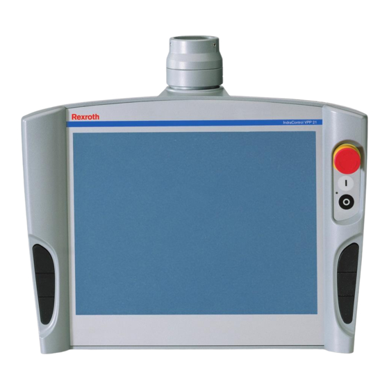
VPP 21.1 System Presentation VPP 21.1 BP In contrast, the VPP 21.1 BP has no keypad, but a touch screen. The front panel with touch screen allows to operate the application software/firmware via the touch-sensitive surface of the display without keyboard and mouse. -
Page 10: Operating System
System Presentation VPP 21.1 Operating System For license reasons the operator terminals VPP 21 are only delivered with already installed operating system. At present, Windows XP is used. The delivered operating systems may only be used in the industrial environment. Use in the office area, e. g. on a secretary's computer, is not allowed. -
Page 11: Important Directions For Use
The user alone carries all responsibility of the risks. Before using Bosch Rexroth products, make sure that all the pre- requisites for appropriate use of the products are satisfied: •... -
Page 12: Areas Of Use And Application
Important Directions for Use VPP 21.1 Areas of Use and Application The operator terminals of Bosch Rexroth are PC-based machine operator and visualization terminals, that are mounted at the machine suspended on a bracket. Note: The operator terminals VPP 21 may only be used with the accessories and parts specified in this document. -
Page 13: Safety Instructions For Electric Drives And Controls
If you do not have the user documentation for your equipment, contact your local Bosch Rexroth representative to send this documentation immediately to the person or persons responsible for the safe operation of this equipment. -
Page 14: Hazards By Improper Use
Safety Instructions for Electric Drives and Controls VPP 21.1 Hazards by Improper Use High voltage and high discharge current! Danger to life or severe bodily harm by electric shock! DANGER Dangerous movements! Danger to life, severe bodily harm or material damage by unintentional motor movements! DANGER High electrical voltage due to wrong... -
Page 15: General Information
VPP 21.1 Safety Instructions for Electric Drives and Controls General Information • Bosch Rexroth AG is not liable for damages resulting from failure to observe the warnings provided in this documentation. • Read the operating, maintenance and safety instructions in your language before starting up the machine. -
Page 16: Protection Against Contact With Electrical Parts
Safety Instructions for Electric Drives and Controls VPP 21.1 • Operation is only permitted if the national EMC regulations for the application are met. The instructions for installation in accordance with EMC requirements can be found in the documentation "EMC in Drive and Control Systems". -
Page 17: Protection Against Electric Shock By Protective Low Voltage (Pelv)
VPP 21.1 Safety Instructions for Electric Drives and Controls To be observed with electrical drive and filter components: High electrical voltage on the housing! High leakage current! Danger to life, danger of injury by electric shock! ⇒ Connect the electrical equipment, the housings of all DANGER electrical units and motors permanently with the safety conductor at the ground points before power is... -
Page 18: Protection Against Dangerous Movements
Safety Instructions for Electric Drives and Controls VPP 21.1 Protection Against Dangerous Movements Dangerous movements can be caused by faulty control of the connected motors. Some common examples are: • improper or wrong wiring of cable connections • incorrect operation of the equipment components •... -
Page 19: Protection Against Magnetic And Electromagnetic Fields During Operation And Mounting
VPP 21.1 Safety Instructions for Electric Drives and Controls ⇒ Secure vertical axes against falling or dropping after switching off the motor power by, for example: - mechanically securing the vertical axes - adding an external braking/ arrester/ clamping mechanism - ensuring sufficient equilibration of the vertical axes The standard equipment motor brake or an external brake controlled directly by the drive controller are not... -
Page 20: Protection Against Contact With Hot Parts
Safety Instructions for Electric Drives and Controls VPP 21.1 Protection Against Contact with Hot Parts Housing surfaces could be extremely hot! Danger of injury! Danger of burns! ⇒ Do not touch housing surfaces near sources of heat! Danger of burns! CAUTION After switching the equipment off, wait at least ten (10) ⇒... -
Page 21: 3.11 Battery Safety
VPP 21.1 Safety Instructions for Electric Drives and Controls 3.11 Battery Safety Batteries contain reactive chemicals in a solid housing. Inappropriate handling may result in injuries or material damage. Risk of injury by incorrect handling! ⇒ Do not attempt to reactivate discharged batteries by heating or other methods (danger of explosion and cauterization). - Page 22 3-10 Safety Instructions for Electric Drives and Controls VPP 21.1 Notes DOK-SUPPL*-VPP*21.1***-PR02-EN-P...
-
Page 23: Technical Data
VPP 21.1 BQ VPP 21.1 BP 14" TFT, 1024 * 768 pixels Display Operation Keys Touch Bosch Rexroth Design Interface Front panel IP 64 according to DIN 40 050, IEC 529 Degree of protection Fig. 4-1: Technical data of the front panel... -
Page 24: Ambient Conditions
Technical Data VPP 21.1 Processor Pentium III with minimum 700 MHz and integrated graphic controller with maximum 4 Mbytes video memory 512 MB SO-DIMM DRAM Main memory • Interfaces 1 x external VGA connection (15-pin, HD-Sub) • 2 x Ethernet connection (RJ 45, 10/100 Base-T) •... -
Page 25: Used Standards
VPP 21.1 Technical Data Note: A slot for a 2.5" hard disk is integrated in the connector panel of the VPP 21 box. If you use a hard disk, which is not suitable for the ambient conditions mentioned in Fig. 4-4:, you must ensure the ambient conditions required by the hard disk manufacturer for the VPP 21. -
Page 26: Wear Parts
50 % of its original brightness. For the used display this time is 10,000 hours. The backlight cannot be separately exchanged. To exchange the display, please contact the Bosch Rexroth Service. • The lithium battery to buffer the static memory has a service life of at least 5 years. -
Page 27: Compatibility Test
(e.g. lubricants in machine tools) which may interact with our controls and drives, it cannot be completely ruled out that any reactions with the materials used by Bosch Rexroth might occur. For that reason, test new lubricants, cleaning agents, etc. for compatibility with our housings / our housing materials before using the particular material concerned. - Page 28 Technical Data VPP 21.1 DOK-SUPPL*-VPP*21.1***-PR02-EN-P...
-
Page 29: Dimensions
VPP 21.1 Dimensions Dimensions Housing Dimensions Housing Dimensions VPP 21.1 BQ The dimensions of the VPP 21.1 with keypad are: VPP-Masse.fh9 Fig. 5-1: Housing dimensions VPP 21 with keypad DOK-SUPPL*-VPP*21.1***-PR02-EN-P... -
Page 30: Housing Dimensions Vpp 21.1 Bp
Provide the cables with strain reliefs. • Keep a suitably large distance from sources of interference. Mounting The VPP 21 is provided for gibbet mounting. As Bosch Rexroth accessories you can order a bracket (see chapter 9, "Ordering information"). Note: The cables are supplied through the gibbet to the VPP 21. -
Page 31: Fig. 5-3: Exemplary Mounting Of The Bracket
For professional, comfortable and easy mounting of the bracket at the machine and the VPP 21, Haseke offers a comprehensive range of additional retainers especially adapted to the bracket delivered by Bosch Rexroth: Haseke GmbH & Co. KG Sandtrift 1, D-32457 Porta Westfalica... - Page 32 Dimensions VPP 21.1 DOK-SUPPL*-VPP*21.1***-PR02-EN-P...
-
Page 33: Display And Operating Components
VPP 21.1 Display and Operating Components Display and Operating Components Display All device variants of the VPP 21 are equipped with a TFT display of seize 14". When leaving the factory, brightness and contrast are already set. The colors can be adapted to the requirements of the environment via the operating system or the application software. -
Page 34: Operator Terminals With Keypad
Display and Operating Components VPP 21.1 Operator Terminals with Keypad The operator terminals VPP 21.1 BQ are equipped with a keypad (IP 64) with 57 keys. Furthermore, three pushbuttons (START, STOP, E-STOP) are integrated in the front panel top right as well as three navigation keys are integrated in the handle bar on the left and the right of the display. -
Page 35: Key Block "Machine
VPP 21.1 Display and Operating Components Key Block "Machine" The key block "Machine" consists of the following three keys: • E-STOP (red, circumvention-proof according to EN 418) • START pushbutton (white, lite) • STOP pushbutton (black) E-STOP START pushbutton STOP pushbutton Vpp21_Tastenblock_Maschine.fh9 Fig. -
Page 36: Key Blocks "Operation
Display and Operating Components VPP 21.1 Key Blocks "Operation" The programmable key blocks "Operation 1 .. 3" contain 16 keys; 14 are equipped with integrated LEDs. Key block Key block Key block "Operation 1" "Operation 2" "Operation 3" VPP21_Tastenbloecke_Bedienung.fh9 Fig. 6-4: Key blocks "Operation"... -
Page 37: Block With Cursor And Special Keys
VPP 21.1 Display and Operating Components Block with Cursor and Special Keys This block joins cursor keys, special keys and the operation of the key mouse: • Cursor keys: right left down • Special keys: Page up (to the top of the page) Page dn (to the bottom of the page) Shift... -
Page 38: Labeling Of The Front Panel
Display and Operating Components VPP 21.1 Labeling of the Front Panel The four function keys F9 to F12 and the twelve keys of the three key blocks "Operation" can be individually labeled by slide-in strips. Two slide-in strips are delivered with the VPP 21. The slide-in strips consist of plastic or laminated paper. -
Page 39: Keyboard Controller
VPP 21.1 Display and Operating Components Keyboard Controller The keypad as well as, if required, an externally connected keyboard are controlled by a controller, that scans the keys and, on the one hand, transmits their key codes to the PC and, on the other hand provides the key codes at 24 volts outputs. - Page 40 Display and Operating Components VPP 21.1 Mouse Repeat Serial Digital numbers outputs Out 24V CTRL-U CTRL-L Bit 1 CTRL-D CTRL-U CTRL-R Bit 2 CTRL-D Bit 1 Bit 2 yellow Bit 3 yellow Bit 4 yellow Bit 5 yellow Bit 6 yellow Bit 7 Bit 8...
-
Page 41: Fig. 6-9: Key Codes
VPP 21.1 Display and Operating Components Key number Mouse Repeat Serial Digital outputs Out 24V Page down Backspace Cursor on Mouse on Bit 4 Shift Cursor left Mouse left Cursor right Mouse right Enter CTRL-I Cursor Mouse Bit 4 down down ‘-’... -
Page 42: Fig. 6-10: Connections Of E-Stop, Start, Stop
6-10 Display and Operating Components VPP 21.1 START, STOP, E-STOP The contacts of the E-STOP pushbutton and the keys START and STOP (S64 to S66) are supplied to a connector strip. This connector strip is situated at the upper edge on the rear side of the VPP 21 under the left door. -
Page 43: Operator Terminals With Touch Screen
6-11 VPP 21.1 Display and Operating Components Operator Terminals with Touch Screen The operator terminals VPP 21.1 BP are equipped with a resistive 4-wire touch screen, that allows the operation of the application software / firmware via the touch-sensitive surface of the displays without keyboard and mouse. -
Page 44: Key Block "Machine
6-12 Display and Operating Components VPP 21.1 Key Block "Machine" The key block "Machine" consists of the following three keys: • E-STOP (red, circumvention-proof according to EN 418) • START pushbutton (white, lite) • STOP pushbutton (black) E-STOP START pushbutton STOP pushbutton Vpp21_Tastenblock_Maschine.fh9 Fig. -
Page 45: Fig. 6-15: Dialog Window To Set The Touch Screen
6-13 VPP 21.1 Display and Operating Components A dialog window appears for the different settings: UPDD_settings.bmp Fig. 6-15: Dialog window to set the touch screen For further information please select the Help button on the respective tab. Via "Start -> Programs -> UPDD" you reach further useful programs, if required. - Page 46 6-14 Display and Operating Components VPP 21.1 DOK-SUPPL*-VPP*21.1***-PR02-EN-P...
-
Page 47: Vpp 21 Box
VPP 21.1 VPP 21 Box VPP 21 Box Connector Panel The connector panel of the VPP 21 box is accessible by opening the cover on the rear side of the VPP 21's plastic housing. VPP21-Zusbau.bmp Fig. 7-1: View of the VPP 21 from the rear side with opened cover DOK-SUPPL*-VPP*21.1***-PR02-EN-P... -
Page 48: Operating And Error Indication
VPP 21 Box VPP 21.1 VPP21-BoxFront.jpg Fig. 7-2: Connector panel of the box build in the VPP 21 Operating and Error Indication To indicate device states and errors 10 LEDs arranged at the connector panel of the VPP 21 box are provided. Start the measures specified in the following table, if one of the succeeding LEDs indicates an error or a note. -
Page 49: Interfaces
VPP 21.1 VPP 21 Box Interfaces Note: Malfunctions caused insufficient shielding! Use only shielded cables and metallic/conductive connector or coupling covers with large-area screen contact. Overview Des. on Type of connection Type of connector Mating connector or cable (integrated) (from outside) housing PS/2 mouse Mini-DIN PS/2 female... -
Page 50: Serial Interface Com1
VPP 21 Box VPP 21.1 Serial Interface COM1 COM1 – The COM1 interface is provided as serial standard interface. Serial Interface Note: The interfaces COM2 and COM3 are used for the touch and the keyboard controller and thus, are not assigned. D-Sub male connector, 9-pin Type: RS232... -
Page 51: Usb Interface
VPP 21.1 VPP 21 Box USB Interface USB – Serial Interface for An USB interface is provided at the VPP 21 box. Printer, Scanner, CD-ROM Drive Via the USB interface up to 128 devices can be connected in series, that are also provided with USB (Universal Serial Bus). -
Page 52: Ethernet Interface
VPP 21 Box VPP 21.1 Ethernet Interface Ethernet – Network Connection The VPP 21 can be connected with Ethernet networks via the interfaces Eth.1 and Eth.2. RJ45 female connector, 8-pin Type: Ethernet 10Base T / 100Base X Cable length: Max. 100 m Cable type: Shielded, 2-core, twisted Transmission rate:... -
Page 53: Vga Interface
VPP 21.1 VPP 21 Box VGA Interface Graphic – Connection for an An external monitor (CRT) can be connected to the VGA connection and External Monitor can be operated parallel to the integrated flat screen via the integrated video adapter. •... -
Page 54: Combined Keyboard/Mouse Interface
VPP 21 Box VPP 21.1 Combined Keyboard/Mouse Interface Keyb. – PS/2 Mini DIN Keyboard / PS/2 Mini-DIN female connector, 6-pin Mouse Interface Cable length: Max. 1.5 m Cable type: Shielded, cross section min. 0.14 mm² Keyb max. 1,5 m Keyb Keyboard Data Keyboard Mouse Data... -
Page 55: Power Supply, Digital Output, Ready Contact
VPP 21.1 VPP 21 Box Power Supply, Digital Output, Ready Contact X10 – 24 VDC Power Supply, The power supply 24 VDC is applied to pin 1 and 2 of the 8-pin male Digital Outputs, connector terminal X10. All internally required voltages are generated with Ready Contact electrical isolation via a DC/DC converter. -
Page 56: Fig. 7-13: Safety Transformer According To En 60742
7-10 VPP 21 Box VPP 21.1 400V + 5% 400V 400V - 5% + 24V sichertrafo.cdr9 Fig. 7-13: Safety transformer according to EN 60742 Interfering AC voltage components such as resulting from an uncontrolled 3-phase current bridge connection without smoothing with a ripple factor (see DIN 40110/10.75, section 1.2) of 5 % are permissible. -
Page 57: Fig. 7-15: Wiring Of The Power Connection 24 Vdc To The Vpp
7-11 VPP 21.1 VPP 21 Box (green/yellow) Power supply with safety transformer acc. to EN 60742 24 VDC Cross-sections depending on current consumption, min. of 4 mm . For higher current con- sumption use 2 x 4 mm . (blue) Length max. -
Page 58: Fig. 7-16: Technical Data: Digital Outputs 1 And
7-12 VPP 21 Box VPP 21.1 Pin 3 and Pin 4: Fan Supply When leaving the factory, there are two fans connected at this pins. This fans are switched on by the VPP 21 box, if the temperature in the box exceeds 50 °C. -
Page 59: Hard Disk
7-13 VPP 21.1 VPP 21 Box Hard Disk The 2.5" hard disk is build in a case and plugged in a special slot at the connector panel. For exchange the case can be pulled out (see chapter 8.2). Compact Flash Card It is possible to insert in slot CF Compact Flash cards with a memory volume of 32 Mbytes to 1 Gbyte and a ATA (IDE) interface. - Page 60 7-14 VPP 21 Box VPP 21.1 DOK-SUPPL*-VPP*21.1***-PR02-EN-P...
-
Page 61: Maintenance And Installation
Maintenance work in the device is only permissible by skilled stuff! If hardware and/or software components have to be ⇒ exchanged, please contact the Bosch Rexroth CAUTION! Service or ensure that only skilled stuff changes the respective components. Include the following measures in your maintenance schedule: Maintenance •... -
Page 62: Hard Disk
Maintenance and Installation VPP 21.1 Hard Disk The hard disk is plugged in the connector field of the VPP 21 box. Thus, the hard disk can easily be exchanged. Loss of data! ⇒ Back up all required application data as well as operating system settings to an external storage medium! CAUTION! -
Page 63: Display
Replace the battery only by a type for the VPP 21 permitted by Bosch Rexroth. At present, this type is: DANGER Lithium battery 3.0 V; 2.3 Ah with Bosch Rexroth part number: 1070922650. Risk of injury through improper treatment of the... -
Page 64: Fig. 8-1: The Battery Is Situated Behind The Left Door
6. Fix the new battery. Consider that the inserted battery type is designed for the VPP 21 and permitted by Bosch Rexroth. At present, this type is: Lithium battery 3.0 V; 2.3 Ah with Bosch Rexroth part number: 1070.922.650. 7. Plug in the connector. -
Page 65: Ordering Information
VPP 21.1 Ordering Information Ordering Information Type Code The VPP 21 is available in various variants according to the following type code. Abbrev. Column 1 2 3 4 6 7 8 9 1 2 3 4 6 7 8 9 1 2 3 4 6 7 8 9 1 2 3 4... -
Page 66: Accessories
Ordering Information VPP 21.1 Accessories Ordering designation Part number Description Rotating joint VPP 21 1070922829 Rotating joint to mount the VPP 21 Bracket VPP 21 1070922717 Bracket to mount the VPP 21 Lithium battery 3.0 V; 2.3 Ah 1070922650 Lithium battery to buffer the RAM Fig. -
Page 67: List Of Figures
10-1 VPP 21.1 List of Figures List of Figures Fig. 1-1: VPP 21.1 BQ 1-2 Fig. 1-2: VPP 21.1 BP 1-3 Fig. 3-1: Hazard classification (according to ANSI Z535) 3-1 Fig. 4-1: Technical data of the front panel 4-1 Fig. 4-2: Technical data of the total device 4-1 Fig. - Page 68 10-2 List of Figures VPP 21.1 Fig. 7-15: Wiring of the power connection 24 VDC to the VPP 21 7-11 Fig. 7-16: Technical data: Digital outputs 1 and 2 7-12 Fig. 7-17: Characteristic data of the ready contact 7-12 Fig. 8-1: The battery is situated behind the left door. 8-4 Fig.
-
Page 69: Index
11-1 VPP 21.1 Index Index Air pressure 4-2 Ambient conditions 4-2 Appropriate use Introduction 2-1 Uses 2-2 Backlight switch-off 6-1 COM1 7-4 Combined keyboard/mouse interface 7-8 Digital outputs 7-9 Dimensions 5-1 Housing dimensions VPP 21.1 BP 5-2 Housing dimensions VPP 21.1 BQ 5-1 Installation notes 5-2 Display 6-1 Display and operating components 6-1... - Page 70 11-2 Index VPP 21.1 Operating and Error Indication 7-2 Operator terminals with keypad 6-2 Operator terminals with touch screen 6-11 Power supply 7-9 PS/2 Keyboard Connection 7-8 PS/2 mouse connection 7-8 Ready contact 7-9 Relative humidity 4-2 Safety Instructions for Electric Drives and Controls 3-1 Safety transformer according to EN 60742 7-10 Serial interface COM1 7-4 Slide-in strips 6-6...
-
Page 71: Service & Support
12-1 VPP 21.1 Service & Support Service & Support 12.1 Helpdesk Unser Kundendienst-Helpdesk im Hauptwerk Lohr Our service helpdesk at our headquarters in Lohr am am Main steht Ihnen mit Rat und Tat zur Seite. Main, Germany can assist you in all kinds of inquiries. Sie erreichen uns Contact us +49 (0) 9352 40 50 60... -
Page 72: 12.5 Kundenbetreuungsstellen
Tel.: +49 (0)171 333 88 26 service.svc@boschrexroth.de Vertriebsgebiet Süd Vertriebsgebiet West Gebiet Südwest Germany South Germany West Germany South-West Bosch Rexroth AG Bosch Rexroth AG Bosch Rexroth AG Landshuter Allee 8-10 Regionalzentrum West Service-Regionalzentrum Süd-West 80637 München Borsigstrasse 15 Siemensstr. 1... - Page 73 - Italien Netherlands - Niederlande/Holland Netherlands – Niederlande/Holland Bosch Rexroth S.p.A. Bosch Rexroth S.p.A. Bosch Rexroth Services B.V. Bosch Rexroth B.V. Via del Progresso, 16 (Zona Ind.) Via Isonzo, 61 Technical Services Kruisbroeksestraat 1 35020 Padova 40033 Casalecchio di Reno (Bo) Kruisbroeksestraat 1 (P.O.
- Page 74 - Tschechien Czech Republic - Tschechien Hungary - Ungarn Poland – Polen DEL a.s. Bosch -Rexroth, spol.s.r.o. Bosch Rexroth Kft. Bosch Rexroth Sp.zo.o. Strojírenská 38 Hviezdoslavova 5 Angol utca 34 ul. Staszica 1 591 01 Zdar nad Sázavou 627 00 Brno 1149 Budapest 05-800 Pruszków...
- Page 75 Australia - Australien Australia - Australien China China AIMS - Australian Industrial Bosch Rexroth Pty. Ltd. Shanghai Bosch Rexroth Shanghai Bosch Rexroth Machinery Services Pty. Ltd. No. 7, Endeavour Way Hydraulics & Automation Ltd. Hydraulics & Automation Ltd. 28 Westside Drive...
- Page 76 Canada West - Kanada West Mexico Mexico Bosch Rexroth Canada Corporation Bosch Rexroth Canada Corporation Bosch Rexroth Mexico S.A. de C.V. Bosch Rexroth S.A. de C.V. Burlington Division 5345 Goring St. Calle Neptuno 72 Calle Argentina No 3913 3426 Mainway Drive Burnaby, British Columbia Unidad Ind.
- Page 78 Bosch Rexroth AG Electric Drives and Controls P.O. Box 13 57 97803 Lohr, Germany Bgm.-Dr.-Nebel-Str. 2 97816 Lohr, Germany Phone +49 (0)93 52-40-50 60 +49 (0)93 52-40-49 41 service.svc@boschrexroth.de www.boschrexroth.com Printed in Germany R911305199 DOK-SUPPL*-VPP*21.1***-PR02-EN-P...