Sign In
Upload
Manuals
Brands
Bosch Manuals
Touch terminals
Rexroth IndraControl VEH 30.1
Bosch Rexroth IndraControl VEH 30.1 Manuals
Manuals and User Guides for Bosch Rexroth IndraControl VEH 30.1. We have
3
Bosch Rexroth IndraControl VEH 30.1 manuals available for free PDF download: Project Planning Manual
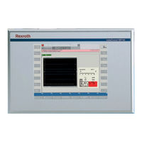
Bosch Rexroth IndraControl VEH 30.1 Project Planning Manual (96 pages)
The embedded terminals are PC-based machine operator terminals
Brand:
Bosch
| Category:
Touch terminals
| Size: 2.75 MB
Table of Contents
Table of Contents
3
System Presentation
7
Brief Description Indracontrol VEP 30.2, VEP 40.2 and VEP 50.2
7
Indracontrol VEP**.2
7
Fig. 1-1: Indracontrol VEP 30.2 - Front Panel
7
Fig. 1-2: Indracontrol VEP 40.2 - Front Panel
7
Fig. 1-3: Indracontrol VEP 50.2 - Front Panel
7
Embedded Terminals with Keypad
8
Embedded Terminals with Touch Screen
8
Front Panel of the Indracontrol VEP 30.2
8
Fig. 1-4: PC Box of the VEP Devices
8
Fig. 1-5: VEP 30.2CC - Front Panel
8
Fig. 1-6: VEP30.2CG - Front Panel
9
Front Panel of the Indracontrol VEP 40.2
10
Fig. 1-7: VEP 40.2CE - Front Panel
10
Front Panel of the Indracontrol VEP 50.2
11
Operating System
11
Commissioning
11
Fig. 1-8: VEP 50.2CH - Front Panel
11
Important Directions for Use
13
Appropriate Use
13
Introduction
13
Areas of Use and Application
14
Inappropriate Use
14
Safety Instructions for Electric Drives and Controls
15
Introduction
15
Explanations
15
Fig. 3-1: Hazard Classification (According to ANSI Z535)
15
Hazards by Improper Use
16
General Information
17
Protection against Contact with Electrical Parts
18
Protection against Electric Shock by Protective Low Voltage (PELV)
19
Protection against Dangerous Movements
20
Protection against Magnetic and Electromagnetic Fields During Operation and Mounting
21
Protection against Contact with Hot Parts
22
3.10 Protection During Handling and Mounting
22
3.11 Battery Safety
23
3.12 Protection against Pressurized Systems
23
Technical Data
25
Front Panel
25
Indracontrol VEP 30.2
25
Indracontrol VEP 40.2
25
Indracontrol VEP 50.2
25
PC Box of the Indracontrol VEP Devices
26
Technical Data of the Indracontrol VEP Power Supply Unit 24 V
26
Fig. 4-4: Technical Data - PC Box of the Indracontrol VEP
26
Fig. 4-5: Technical Data of the Indracontrol VEP Power Supply Unit
26
Ambient Conditions
27
Indracontrol VEP
27
Weights
27
Fig. 4-6: Indracontrol VEP - Ambient Conditions
27
Fig. 4-7: Indracontrol VEP - Weights
27
Used Standards
28
Fig. 4-8: Used Standards
28
Wear Parts
29
Compatibility Test
29
Fig. 4-9: Capacitor Pack
29
Dimensions
31
Housing Dimensions
31
Housing Dimensions of the Indracontrol VEP 30.2CC
31
Fig. 5-1: VEP 30.2CC - Front Panel
31
Fig. 5-2: VEP 30.2CC - Side View
32
Fig. 5-3: VEP 30.2CC - Top View
32
Housing Dimensions of the Indracontrol VEP 30.2CG
33
Fig. 5-4: VEP 30.2CC - Bottom View
33
Fig. 5-5: VEP 30.2CG - Front View
33
Fig. 5-6: VEP 30.2CG - Rear View
34
Housing Dimensions of the Indracontrol VEP 40.2CE
35
Fig. 5-7: VEP 40.2CE - Front Panel
35
Fig. 5-8: VEP 40.2CE - Side View
36
Fig. 5-9: VEP 40.2CE - Top View
36
Housing Dimensions of the Indracontrol VEP 50.2CH
37
Fig. 5-10: VEP 40.2CE - Bottom View
37
Fig. 5-11: VEP 50.2CH - Front Panel
37
Fig. 5-12: VEP 50.2CH - Side View
38
Fig. 5-13: VEP 50.2CH - Top View
38
Installation of a Second PC104 Card
39
Installation
39
Installation Notes
39
Mounting Cut-Out
39
Fig. 5-14: VEP 50.2CH - Bottom View
39
Mounting Dimensions of the Indracontrol VEP 30.2CC
40
Fig. 5-15: Mounting Dimensions of the Indracontrol VEP 30.2CC
40
Mounting Dimensions of the Indracontrol VEP 30.2Cg's Bracket Housing
41
Fig. 5-16: Mounting Dimensions - Bracket Housing of the Indracontrol
41
Mounting Dimensions of the Indracontrol VEP 40.2CE
42
Fig. 5-17: Mounting Dimensions of the Indracontrol VEP 40.2CE
42
Mounting Dimensions of the Indracontrol VEP 50.2CH
43
Fig. 5-18: Mounting Dimensions of the Indracontrol VEP 50.2CH
43
Display and Operating Components
45
Backlight Switch-Off
45
Fig. 6-1: Graphics Properties - Backlight Dimming
45
Operating Components of the Indracontrol VEP 30.2CG
46
Keypad
46
Fig. 6-2: Position of the Keys
46
Fig. 6-3: Keys of the Indracontrol VEP 30.2CG
46
Touch Screen
47
Pin Assignments of the Indracontrol VEP
49
Connector Panel Without Special Interfaces
49
Connector Panel with PROFIBUS DP Master
49
Connector Panel with PROFIBUS DP Master and Exemplarily Second PC104 Plug-In Card
49
Interfaces of the Indracontrol VEP
50
Overview
50
Serial Interface COM1
51
USB Interfaces
52
Fig. 7-7: USB Interfaces
52
Fig. 7-8: Pin Assignment of the USB Interfaces
52
Ethernet Interfaces
53
VGA Interface
54
Fig. 7-11: VGA Connection
54
Fig. 7-12: Pin Assignment of the VGA Interface
54
Combined Keyboard/Mouse Interface
55
24 VDC Power Supply
55
Fig. 7-13: Keyboard/Mouse Interface
55
Fig. 7-14: Pin Assignment of the Keyboard/Mouse Interface
55
Fig. 7-15: Pin Assignment of the 24 VDC Connection X10
55
Fig. 7-16: Technical Data of the 24 VDC Connection
55
Fig. 7-17: Safety Transformer According to en 60742
56
Fig. 7-18: Illustration of the Limit Values for the 24 VDC Voltage
56
Fig. 7-19: Wiring of the Power Connection 24 VDC and the Embedded Terminal
57
PROFIBUS Master Interface DP-M
58
PROFIBUS Diagnostic Interface Config
58
Fig. 7-20: Pin Assignment of the PROFIBUS Master Interface
58
Fig. 7-21: Pin Assignment of the Diagnostic Interface RS232C
58
Fig. 7-22: Technical Data PROFIBUS Master Interface
58
Cable Outlet of the VEP30.2CG
60
Fig. 7-23: Cable Outlet of the VEP30.2CG
60
Maintenance and Installation
61
General Information
61
LCD Display
61
CMOS Battery
62
Extension Cards
62
Software
63
General Information
63
Fig. 9-1: Firmware Types
63
Fig. 9-2: Software Options
63
First Commissioning
64
Touch Calibration
64
Fig. 9-3: Touch Calibration of the Indracontrol VEP
64
Rexroth CE Settings
65
Rexroth CE Settings - Ethernet Adapter
65
Fig. 9-4: Rexroth CE Settings - Ethernet Adapter
65
Rexroth CE Settings - Application Settings
66
Fig. 9-5: Rexroth CE Settings - Application Settings
66
Rexroth CE Settings - Data Server
67
Fig. 9-6: Rexroth CE Settings - Data Server
67
Rexroth CE Settings - System Info
68
Fig. 9-7: Rexroth CE Settings - System Info
68
Windows CE 4.2 .NET
69
Operation
69
Fig. 9-8: Windows CE 4.2 .NET Desktop
69
Memory Distribution
70
Fig. 9-9: System Properties - Memory
70
Fig. 9-10: Selecting the Virtual Keyboard
71
Fig. 9-11: Virtual Keyboard, Small
71
Fig. 9-12: Virtual Keyboard, Large
71
USB Support of the Indracontrol VEP
72
Microsoft Programs
72
Fig. 9-13: Released USB Devices
72
FTP Server
73
Web Server
73
Telnet Server
73
CE User Configuration
73
Indralogicwince
74
Winstudio
74
Fig. 9-14: Enabling the Indralogicwince
74
Fig. 9-15: Functional Range of Winstudio "Lite
74
Fig. 9-16: Winstudio CE Server - Remote Agent
75
Fig. 9-17: Remote Agent Setup
75
Ordering Information
77
10.1 Type Code
77
Vep 30.2
78
Fig. 10-1: VEP 30.2 - Type Code
78
Fig. 10-2: VEP 30.2 - Type Code, Continuation
78
Vep 40.2
79
Fig. 10-3: VEP 40.2 - Type Code
79
Vep 50.2
80
10.2 Accessories
81
Connectors and Ready-Made Cables
81
Storage Media
81
11 List of Figures
83
Index
87
Helpdesk
89
Sales & Service Facilities
90
Advertisement
Bosch Rexroth IndraControl VEH 30.1 Project Planning Manual (86 pages)
Brand:
Bosch
| Category:
Touch terminals
| Size: 1.54 MB
Table of Contents
Table of Contents
3
1 System Presentation
7
Brief Description
7
Keypad
7
Touch Screen
7
Front View of the Indracontrol VEH 30.1
8
Front View of the Indracontrol VAC 30.1
9
Operating System
9
Commissioning
10
2 Important Directions for Use
13
Appropriate Use
13
Introduction
13
Areas of Use and Application
14
Inappropriate Use
14
3 Safety Instructions for Electric Drives and Controls
15
Introduction
15
Explanations
15
Fig. 3-1: Hazard Classification (According to ANSI Z535)
15
Hazards by Improper Use
16
General Information
17
Protection against Contact with Electrical Parts
18
Protection against Electric Shock by Protective Low Voltage (PELV)
19
Protection against Dangerous Movements
20
Protection against Magnetic and Electromagnetic Fields During Operation and Mounting
21
Protection against Contact with Hot Parts
22
3.10 Protection During Handling and Mounting
22
3.11 Battery Safety
23
3.12 Protection against Pressurized Systems
23
4 Technical Data
25
Operating Surface
25
STOP Pushbutton
25
Fig. 4-3: Technical Data of the STOP Pushbutton
25
Enabling Device
26
Connection Module Indracontrol VAC 30.1
26
Fig. 4-4: Technical Data of the Enabling Device
26
Ambient Conditions
27
Identification
28
Weight
28
Used Standards
29
Fig. 4-9: Used Standards
29
4.10 Wear Parts
30
4.11 Compatibility Test
30
5 Dimensions
31
Housing Dimensions of the Indracontrol VEH 30.1
31
Housing and Mounting Dimensions of the Indracontrol VAC 30.1
32
Fig. 5-2: Housing and Mounting Dimensions of the Indracontrol VAC
32
Dimensions of the Wall Holder for the Indracontrol VEH 30.1
33
6 Display and Operating Components
35
Operating Elements
35
Housing of the Indracontrol VEH 30.1
35
Fig. 6-3: Handling of the Indracontrol VEH 30.1
36
Keypad
38
Touch Screen
38
Safety Operating Components
39
Fig. 1-1: Indracontrol VEH 30.1
40
Fig. 6-5: STOP Circuit Jumpering
40
Fig. 6-6: Time Course When Connecting the Indracontrol VEH 30.1 STOP Circuit
41
Optional Operating Elements
42
Backlight Dimming
42
Fig. 6-8: Display Properties - Backlight Dimming
42
7 Interfaces of the Indracontrol VEH 30.1
43
Connection of the Indracontrol VEH 30.1 Via the Indracontrol VAC 30.1
43
Pin Assignment of the Indracontrol VAC 30.1
43
Fig. 7-1: Pin Assignment of the Indracontrol VAC 30.1 Connection Module
43
Fig. 7-2: Pin Assignment of the Indracontrol VAC 30.1 Connection Module
43
X1: 24 VDC Voltage Supply
44
Fig. 7-3: Pin Assignment of the 24 VDC Power Supply X1
44
Fig. 7-4: Technical Data of the 24 VDC Connection
44
Fig. 7-5: Safety Transformer According to en 60742
45
Fig. 7-6: Illustration of the Limit Values for the 24 VDC Voltage
45
X2.1: STOP Pushbutton
46
Fig. 7-7: Wiring of Power Connection 24 VDC to the Embedded Terminal
46
Fig. 7-8: Pin Assignment of the STOP Pushbutton X2.1
46
X2.2: Enabling Device
47
Fig. 7-9: Enabling Device X2.2
47
Fig. 7-10: Circuit Diagram of the Enabling Device
47
Fig. 7-11: Contact Travel Diagram
48
Fig. 7-12: Internal Wiring: Category
50
Fig. 7-14: Internal Wiring: Category
51
X3: Ethernet Interface
52
Fig. 7-15: Ethernet Interface
52
Fig. 7-16: Pin Assignment of the Ethernet Interface X3
52
Personality Function
53
8 Maintenance and Installation
55
General Information
55
LCD Display
55
Maintenance of the Indracontrol VEH 30.1
55
Measures in Case of Malfunctions at the Indracontrol VEH 30.1
56
9 Software
57
General Information
57
First Commissioning
57
Fig. 9-2: Software Options
57
Touch Screen Calibration
58
Rexroth CE Settings
58
Ethernet Adapter
59
Fig. 9-4: Rexroth CE Settings - Ethernet Adapter
59
Application Settings
60
Fig. 9-5: Rexroth CE Settings - Application Settings
60
Data Server
61
Fig. 9-6: Rexroth CE Settings - Data Server
61
System Info
62
Fig. 9-7: Rexroth CE Settings Indracontrol VEH 30.1 - System Info
62
Windows CE 4.2 .NET
63
Operation
63
Fig. 9-8: Windows CE 4.2 .NET Desktop
63
Fig. 9-9: Selecting the Virtual Keyboard
64
Fig. 9-10: Virtual Keyboard, Small
64
Fig. 9-11: Virtual Keyboard, Large
64
Microsoft Programs
65
FTP Server
66
Web Server
66
Telnet Server
66
CE User Configuration
66
Winstudio
67
Fig. 9-12: Functional Range of Winstudio "Lite
67
Fig. 9-13: Winstudio CE Server - Remote Agent
67
Evaluation of the Operating Element Commands
68
Fig. 9-14: Remote Agent Setup
68
Evaluation of the Operating Status in the Control
69
Evaluation of the Keys in the Operating System
70
Fig. 9-15: Bit Assignment with Function Block
70
System Update
71
Preparation
71
Upload Via FTP Server
72
10 Ordering Information
73
10.1 Type Code
73
Indracontrol VAC 30.1
74
10.2 Accessories
74
Extension Cable
74
Wall Holder
74
10.3 Spare Parts
74
Touch Pen
74
11 List of Figures
75
12 Index
77
13 Service & Support
79
13.1 Helpdesk
79
13.2 Service-Hotline
79
13.3 Internet
79
Vor der Kontaktaufnahme
79
Kundenbetreuungsstellen
80
Sales & Service Facilities
80
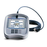
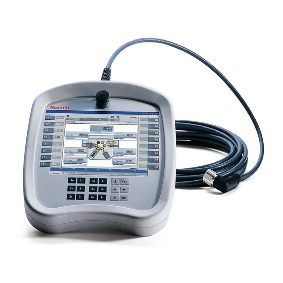
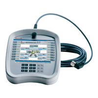
Bosch Rexroth IndraControl VEH 30.1 Project Planning Manual (76 pages)
Hand-Held Terminal
Brand:
Bosch
| Category:
Touch terminals
| Size: 1.56 MB
Table of Contents
Table of Contents
3
1 System Presentation
7
Short Description
7
General Information
7
Foil Keyboard
7
Touch Screen
7
Front View of the Indracontrol VEH 30.1
8
Indracontrol VEH 30.1 with Touch Screen and Keypad
8
Front View of the Indracontrol VAC 30.2
8
Operating System
9
Commissioning
9
2 Important Instructions on Use
11
Appropriate Use
11
Introduction
11
Areas of Use and Application
11
Inappropriate Use
12
3 Safety Instructions for Electric Drives and Controls
13
Safety Instructions - General Information
13
Using the Safety Instructions and Passing Them on to Others
13
How to Employ the Safety Instructions
13
Explanation of Warning Symbols and Degrees of Hazard Seriousness
14
Hazards by Improper Use
15
Instructions with Regard to Specific Dangers
16
Protection against Contact with Electrical Parts and Housings
16
Protection against Electric Shock by Protective Extra-Low Voltage
17
Protection against Dangerous Movements
17
Protection against Magnetic and Electromagnetic Fields During Operation and Mounting
20
Protection against Contact with Hot Parts
20
Protection During Handling and Mounting
20
Battery Safety
21
Protection against Pressurized Systems
21
4 Technical Data
23
Indracontrol VEH 30.1
23
Front Panel
23
STOP Pushbutton
23
Enabling Device
24
Connection Module Indracontrol VAC 30.2
24
Ambient Conditions
24
Coding
25
Weight
25
Used Standards
25
UL/CSA Certified
26
Wear Parts
26
Compatibility Test
27
5 Dimensions
29
Housing Dimensions of the Indracontrol VEH 30.1
29
Top View: VEH 30.1
29
Side View: VEH 30.1
30
Housing and Mounting Dimensions of the Indracontrol VAC 30.2
31
Dimensions of the Wall Holder for the Indracontrol VEH 30.1
32
6 Display and Operating Components
33
Operating Components
33
General Information
33
Housing of the Indracontrol VEH 30.1
33
Foil Keyboard
36
Position of the Keys of the Indracontrol VEH 30.1
36
Touch Screen
36
Safety Operating Components
37
Optional Operating Components
39
Backlight Dimming
39
7 Pin Assignment of Indracontrol VEH 30.1
41
Connection of the Indracontrol VEH 30.1 Via the Indracontrol VAC 30.2
41
General Information
41
Pin Assignment of the Indracontrol VAC 30.2
41
X1: 24 VDC Power Supply
42
X2.1: STOP Pushbutton
44
Pin Assignment
44
X2.2: Enabling Device
45
Pin Assignment
45
Circuit Diagram of the Enabling Device
45
Contact Travel Diagram of the Enabling Device
46
Wiring of the Enabling Device
46
X3: Ethernet Interface
49
Personality Function
50
8 Maintenance and Installation
51
General Information
51
LCD Display
51
Maintenance of the Indracontrol VEH 30.1
51
Measures in Case of Malfunctions at the Indracontrol VEH 30.1
51
9 Software
53
General Information
53
First Commissioning
53
Touch Screen Calibration
53
Rexroth CE Settings
54
General Information
54
Ethernet Adapter
54
Application Settings
55
Data Server
56
System Info
56
Windows CE 4.2 .NET
57
General Information
57
Operation
57
Microsoft Programs
58
General Information
58
FTP Server
59
Web Server
59
Telnet Server
59
CE User Configuration
60
Winstudio
60
General Information
60
Remote Agent Setup
61
Evaluation of the Operating Element Commands
61
General Information
61
Evaluation of the Operating Status in the Control
61
Evaluation of the Keys in the Operating System
63
System Update
64
General Information
64
Preparation
64
Upload Via FTP Server
65
10 Environmental Protection and Disposal
67
Environmental Protection
67
Disposal
67
11 Ordering Information
69
Type Designation Code
69
General Information
69
Indracontrol VEH 30.1
69
Indracontrol VAC 30.2
70
Accessories
70
Extension Cable
70
Wall Holder
70
Spare Parts
70
Touch Pen
70
Advertisement
Advertisement
Related Products
Bosch Rexroth IndraControl VEP .2 Series
Bosch Rexroth IndraControl VEP30.2
Bosch Rexroth IndraControl VEP40.2
Bosch Rexroth IndraControl VEP50.2
Bosch Rexroth IndraControl VEP 30.1
Bosch Rexroth IndraControl VEP 40.1
Bosch Rexroth IndraControl VEP 50.1
Bosch Rexroth IndraControl VEP 30.4
Bosch Rexroth IndraControl VEP 40.4
Bosch Rexroth IndraControl VEP 50.4
Bosch Categories
Dishwasher
Washer
Oven
Power Tool
Dryer
More Bosch Manuals
Login
Sign In
OR
Sign in with Facebook
Sign in with Google
Upload manual
Upload from disk
Upload from URL