
Related Manuals for Lincoln Electric Power Feed 84


Summary of Contents for Lincoln Electric Power Feed 84
- Page 1 IM2060 05/2017 REV01 POWER FEED 84, POWER FEED 84 DUAL, POWER FEED 84 U.I. CONTROL BOX OPERATOR’S MANUAL ENGLISH THE LINCOLN ELECTRIC COMPANY 22801 St. Clair Ave., Cleveland Ohio 44117-1199 USA www.lincolnelectric.eu...
- Page 2 THE LINCOLN ELECTRIC COMPANY EC DECLARATION OF CONFORMITY Manufacturer and technical The Lincoln Electric Company documentation holder: 22801 St. Clair Ave. Cleveland Ohio 44117‐1199 USA EC Company: Lincoln Electric Europe S.L. a c/o Balmes, 89 ‐ 8 2 08008 Barcelona SPAIN Hereby declare that equipment: Power Feed 84 K3328, K3330 Power Feed 84 One‐Pak K3329, K3331 (Product numbers may contain suffixes and prefixes.) Is in conformity with Council ...
-
Page 3: Table Of Contents
12/05 THANKS! For having chosen the QUALITY of the Lincoln Electric products. Please Examine Package and Equipment for Damage. Claims for material damaged in shipment must be notified immediately to the dealer. For future reference record in the table below your equipment identification information. Model Name, Code &... -
Page 4: Technical Specifications
Technical Specifications POWER FEED 84 CE, POWER FEED 84 DUAL CE: K3328-xx, K3329-xx, K3330-xx, K3331-xx, K3336-xx INPUT VOLTAGE AND CURRENT Voltage Input Amperes Notes Wire Drive 40VDC User Interface RATED OUTPUT @ 40°C Duty Cycle Input Amperes Wire Drive Only... - Page 5 SINGLE WIRE DRIVE FEEDERS Wire Reel Control Inlet Gouging MODEL K# User Interface Contactor Stand Adapter Cable Bushing K3328-1 BLANK PANEL STD #2-#4 K3929-1 FULL DISPLAY K3328-2 WITH STD #2-#4 K3929-1 MEMORIES FULL DISPLAY K3328-3 WITH STD #2-#4 K3929-1 MEMORIES FULL DISPLAY K3328-6 WITH...
-
Page 6: Electromagnetic Compatibility (Emc)
Lincoln Electric. Before installing the machine, the operator must check the work area for any devices that may malfunction because of electromagnetic disturbances. -
Page 7: Safety
Failure to follow the instructions in this manual could cause serious personal injury, loss of life, or damage to this equipment. Read and understand the following explanations of the warning symbols. Lincoln Electric is not responsible for damages caused by improper installation, improper care or abnormal operation. -
Page 8: Introduction
The EMC or RF classification of this equipment is Class A. Do not submerge the Power Feed 84. The Power Feed 84 is rated IP2x and is suitable for indoor use. When suspending a wire feeder, insulate the hanging 15 DEGREES MAXIMUM device from the wire feeder enclosure. - Page 9 Figure #4 Single/Dual User Interface Conversion (See Figure #5) The Power Feed 84 uses the same user interface for both single and dual models. A DIP switch on the back side of the user interface board sets the board configuration.
- Page 10 Figure #6 Requires: K3336-3 User Interface. Turn power OFF at the welding power source. Wire Drive (see Figure #7) Remove the (4) screws securing the user interface User Interface to the wire drive. Disconnect the harness from the 4 4 pin connector User Interface pin connector on the back of the user interface.
- Page 11 Installing Drive Rolls (See Figure #9) Inner Wire Drive Drive Rolls C. Outer Wire Drive Figure #9 Turn power OFF at the welding power source. Open the wire drive door by pulling on the top. Remove the outer wire guide. Pressure adjust knob Remove drive rolls by pulling straight out.
- Page 12 With a 3/4” wrench, remove the bolt holding the electrode lead to the gun adapter. Set Screw Guide Tube Figure #15 Number of grooves in Wire size guide tube 0.6 – 1.2mm Bolt 1.2 – 1.6 mm Electrode Lead 1.6 – 2.0 mm Figure #12 2.0 –...
- Page 13 Oxo and Fast Mate Gun Adapter Assemble the gun adapter cover and secure with the screw. Installation Using the Oxo or FastMate gun adapters requires a K3344-1 Standard #4 gun adapter to be installed in the wire drive. Turn power OFF at the welding power source. Using a Phillips screw driver, loosen the screw securing the gun adapter cover.
- Page 14 Enter the set-up menu and select P.18. Adjust to Rotate the wire drive to the desired position and match the pinion gear installed. tighten the screw. 10. Turn power OFF, then back ON for the settings to take effect. Pinion Gear Ratio Shielding Gas Connection As shipped from the factory, a 20 tooth pinion gear is installed.
- Page 15 Loading Spools of Wire 22 – 27 kg coils require K3343-1 Heavy Duty Wire Reel Stand Turn power OFF at the welding power source. Squeeze the release bar on the retaining collar and remove it from the spindle. SQUEEZE RELEASE BAR A.
- Page 16 ** Tabled values are for operation at ambient temperatures of 104°F(40°C) and below. Applications above 104°F(40°C) may require cables larger than recommended, or cables rated higher than 167°F(75°C). Negative Electrode Polarity The Power Feed 84 ships from the factory configured for electrode positive polarity. See P.81 in the Operations Section (Set-Up menu) to select negative polarity welding.
- Page 17 Welding with Multiple Arcs Special care must be taken when more than one arc is welding simultaneously on a single part. Arc blow and arc interference may occur or be magnified. Each power source requires a work lead from the work stud to the welding fixture.
- Page 18 – wire feed speed, voltage, trigger type, GAS PURGE procedure, etc. GRAPHIC SYMBOLS THAT APPEAR ON SHIELDING GAS INLET POWER FEED 84, POWER FEED 84 DUAL OR IN THIS MANUAL SHIELDING GAS OUTLET WARNING or CAUTION MEMORY SAVED...
- Page 19 The Power Feed 84 does not operate with LincNet Power Sources. The power source may require a software update. If the Power Feed 84 has contactors or a gouging kit installed, the power source software may require updated. Does not include weld cables ...
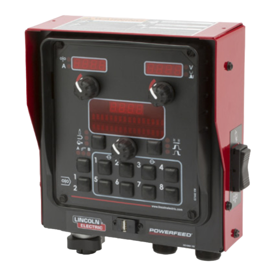
- Page 20 Voltage/Trim Display and Knob The right display and knob control voltage, trim or output depending upon the process selected. Once welding is complete, the display continues to show the welding voltage for 5 seconds. Process Display/Function Description Rotate clockwise to turn output ON. Rotate counterclockwise to turn output OFF SMAW (Stick) and GTAW...
- Page 21 Voltage/Trim Display and Knob Process Display/Function Description Pulse welding controls the arc length with 'Trim' instead of voltage. When trim (arc length) is adjusted, the Power Wave automatically recalculates the voltage, current and time of each part ofthe pulse waveform for the best result.
- Page 22 Wave Control Process Wave Effect/Range Description Control Name Arc Force adjusts the short circuit current for a soft arc, or for a forceful, driving arc. It helps to prevent sticking and shorting of organic coated SMAW Soft (-10.0) to electrodes, particularity globular transfer types such as stainless and low Arc Force (Stick) Crisp (10.0)
- Page 23 Wave Control Process Wave Effect/Range Description Control Name Peak Current acts similar to an arc pinch control. Peak Current sets the arc length and promotes good fusion. Higher peak current levels will cause the arc to broaden momentarily while increasing arc length. If set too high, globular transfer may occur.
- Page 24 2-Step Trigger 2-Step Trigger controls the welding sequence in direct response to the trigger. When the gun trigger is pulled, the welding system (power source and wire feeder) cycles through the arc starting sequence and into the main welding parameters. The welding system will continue to weld as long as the gun trigger is activated. Once the trigger is released, the welding system cycles through the arc ending steps.
- Page 25 Example 2: 2-Step Trigger: Improved Arc Start and Arc End Tailoring the arc start and arc end is a common method for reducing spatter and improving weld quality. This can be accomplished with the Start and Burnback functions set to a desired values and Crater set to OFF. For this sequence, PREFLOW: Shielding gas begins to flow immediately when the gun trigger is pulled.
- Page 26 Example 3: 2-Step Trigger: Customized Arc Start, Crater and Arc End. Aluminum is an example of where start, crater and burnback are commonly used to improve welding performance. For this sequence, PREFLOW: Shielding gas begins to flow immediately when the gun trigger is pulled. RUN-IN: After preflow time expires, the power source regulates to the start output and wire is advanced towards the work piece at the Run-In WFS.
- Page 27 4-Step Trigger 4-step trigger allows the operator to release the trigger once an arc has been established. To end the weld, the trigger is pulled and then released again. Two types of 4-Step Trigger are available. Use the set-up menu to select the desired type of operation. With current interlock, if the arc goes out for more than 0.5 seconds while the trigger is released, the welding process stops and goes to the idle state.
- Page 28 Example 2: 4-Step Trigger: Manual Control of Start and Crater times with Burnback ON. The 4-Step trigger sequence gives the most flexibility when the Start, Crater and Burnback functions are active. This is a popular choice when welding aluminum because extra heat may be needed during Start and less heat desired during crater.
- Page 29 Spot Trigger The Spot Trigger may only be selected if the Spot Time has previously been set to a value other than 0.0 (OFF) and the Start and Crater are both OFF. Spot time causes the welding system to turn on for a fixed time, regardless if the trigger is held for a longer period of time.
- Page 30 4-Step Trigger: Special Considerations The response to the trigger with 4-step trigger active is dependent upon when the trigger is pulled/released and the settings for START and CRATER. Example 1. Pull the trigger to start feed of wire. When arc is established the sequencer will remain in START until the trigger is released.
- Page 31 End Options The End Options available depend upon the process and weld mode selected Process Start Options Effect / Range Description SMAW (Stick) Spot Timer Sets the length of time for welding when the trigger is pulled. If the trigger is released before the Spot Timer is complete, welding stops.
- Page 32 For example, to recall memory 3, quickly pull functions: and release the gun trigger 3 times without welding. Note: the Power Feed 84 is factory set with this feature Weld procedure selection disabled. Use the SETUP menu and change P.4 to Memory save and recall enable memory recall with the gun trigger.
- Page 33 attempt is made to save a memory when memory saving Setup menu, and must be chosen and saved to memory is locked, the message "Memory save is Disabled!" will before entering the Limits Setup Menu. appear briefly in the display. To set limits, press the desired memory button 1-8 and hold for 5 seconds.
- Page 34 through P.513 (the prompt is enabled by default). The memory value must always be less than or equal to the high limit, and greater than or equal to the low limit. To load memories from the USB: Enter the set-up menu, scroll to P.37 and hit the After setting limits, press the memory button with the right button (if not in the USB prompt) number.
- Page 35 Set-Up Menu USER DEFINED PARAMETERS Parameter Name and Description Range Exit Setup Menu This option is used to exit the setup menu. When P.0 is displayed, press the Left Button to exit the setup menu. Wire Feed Speed Units English, Metric This option selects which units to use for displaying wire feed speed.
- Page 36 Note: The range was changed to -90 to +90 for the PF25M in WD software S28539-3. Default value remains at 0. On dual-head Power Feed 84 Feeders, a different setting can be used for each head. The operator will be prompted to select which head to edit before the setting can be changed.
- Page 37 If the trigger is released after the timer expires, the Crater sequence will function normally (if enabled). On dual-head Power Feed 84 Feeders, a different setting can be used for each head. The operator will be prompted to select which head to edit before the setting can be changed.
- Page 38 6-pin and 7-pin remote control connections operate. This setting was provided so that customers with a mix of Lincoln Electric equipment can have consistent remote control behavior across all of their equipment. (N. American default) Joystick MIG Gun = Use this setting while MIG welding with a push MIG gun with a joystick control.
- Page 39 Parameter Name and Description Range P.18 Wire Drive Gear Ratio This option selects the Wire Drive Gear Ratio that will be used. The possible selectable values are read from the Wire Drive on startup. For semi-automatic systems, if the feedhead board has dip switches, this option does not appear in the menu.
- Page 40 (default is 0%) can range from -5% to +5% of normal speed. On dual-head Power Feed 84 Feeders, a different setting can be used for each head. The operator will be prompted to select which head to edit before the setting can be changed.
- Page 41 Positive Electrode Welding (default). Electrode Welding Negative Electrode Welding. On dual-head Power Feed 84 Feeders, a different setting can be used for each head. The operator will be prompted to select which head to edit before the setting can be changed. P.82 Voltage Sense Display Allows viewing of Voltage Sense Lead Selection to aid in troubleshooting.
- Page 42 Parameter Name and Description Range P.99 Show Test Modes Most power sources contain weld modes used for calibration and test purposes. By default, the machine does not include test weld modes in the list of weld modes that are available to the operator. To manually select a test weld mode, set this option to "Yes".
- Page 43 Parameter Name and Description Range P.502 Memory Change Lockout No, Yes Determines if the memories can be overwritten with new contents. Unlocked = Memories can be saved and limits can be configured (default). Fully Locked = Memories cannot be changed - saving is prohibited and limits cannot be reconfigured.
- Page 44 Parameter Name and Description Range P.512 USB Options This setting is used to enable and disable which USB options can be used on the feeder. Available selec- tions are as follows: (1) No Options = No USB options will be available for use. P.37 will not be available, and the USB prompt will be disabled.
- Page 45 If the wire feeder is turned on with the process switch in the gouging position, the welding output will turn on. Electric Shock can kill. Turn the input power OFF at the The Power Feed 84 is available from the factory with the welding power source before gouging kit installed.
- Page 46 We respond to our customers based on the best information in our possession at that time. Lincoln Electric is not in a position to warrant or guarantee such advice, and assumes no liability, with respect to such information or advice. We expressly disclaim any warranty of any kind, including any warranty of fitness for any customer’s particular purpose,...
-
Page 47: Weee
WEEE 07/06 Do not dispose of electrical equipment together with normal waste! In observance of European Directive 2012/19/EC on Waste Electrical and Electronic Equipment (WEEE) and its implementation in accordance with national law, electrical equipment that has reached the end of its life must be collected separately and returned to an environmentally compatible recycling facility. -
Page 48: Electrical Schematic
Electrical Schematic WIRING DIAGRAM – POWER FEED 84 WIRE DRIVE – SINGLE (ABOVE CODE 12000) NOTE: this diagram is for reference only. It may not be accurate for all machines covered by this manual. The specific diagram for a partiuclar code is pasted inside the machine on one of the enclosure panels. If the diagram is ellegible, write to the Service Department for a raplacement. - Page 49 WIRING DIAGRAM – POWER FEED 84 WIRE DRIVE – 1 DUAL (ABOVE CODE 12200) NOTE: this diagram is for reference only. It may not be accurate for all machines covered by this manual. The specific diagram for a partiuclar code is pasted inside the machine on one of the enclosure panels. If the diagram is ellegible, write to the Service Department for a raplacement.
- Page 50 WIRING DIAGRAM – POWER FEED 84 WIRE DRIVE – 2 DUAL (ABOVE CODE 12200) NOTE: this diagram is for reference only. It may not be accurate for all machines covered by this manual. The specific diagram for a partiuclar code is pasted inside the machine on one of the enclosure panels. If the diagram is ellegible, write to the Service Department for a raplacement.
- Page 51 WIRING DIAGRAM – POWER FEED 84 CONTROL BOX WITH USB FOR CODES 12177, 12178, 12179 NOTE: this diagram is for reference only. It may not be accurate for all machines covered by this manual. The specific diagram for a partiuclar code is pasted inside the machine on one of the enclosure panels. If the diagram is ellegible, write to the Service Department for a raplacement.
-
Page 52: Suggested Accessories
Suggested Accessories DRIVE ROLL AND WIRE GUIDE KITS Drive Roll Kits, Steel Wires KP1505-030S 0.6-0.8mm KP1505-035S 0.9mm KP1505-045S 1.2mm KP1505-052S 1.4mm Includes: 4 Smooth V groove drive rolls and inner wire guide. KP1505-1/16S 1.6mm KP1505-1 0.9, 1.2mm KP1505-2 1.0mm Drive Roll Kits, Cored Wires KP1505-035C 0.8-0.9mm KP1505-045C... - Page 53 K3929-1 Quick Connect Conduit Inlet Bushing. Quick disconnect inlet bushing for Electron Beam Technologies con- duit. ACCESSORIES INCLUDED WITH THE POWER FEED 84 Wire drives include a Standard #2-#4 gun adapter. 30 tooth pinion gear. ...