Table of Contents
Advertisement
Advertisement
Table of Contents

Related Manuals for Trane IntelliPak SCWG 020, SCWG 025, SCWG 030, SCWG 035, SWG 020, SWG 025, SWG 030, SWG 035, SCRG 020, SCRG 025, SCRG 032, SRG 020, SC


Summary of Contents for Trane IntelliPak SCWG 020, SCWG 025, SCWG 030, SCWG 035, SWG 020, SWG 025, SWG 030, SWG 035, SCRG 020, SCRG 025, SCRG 032, SRG 020, SC
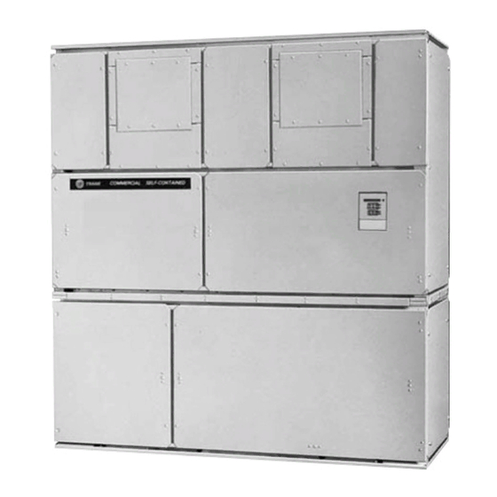
- Page 1 Installation, Owner, and Diagnostic Manual ® IntelliPak Commercial Self-Contained Modular Series, 20-35 T on Models “BO” and later Design Sequence SCWG -020, -025, -030, -035 SIWG -020, -025, -030, -035 SCRG -020, -025, -032 SIRG -020, -025, -032 July 2000 SCXG-SVX01B-EN...
- Page 2 CFC fully halogenated compounds. The Trane Company urges all HVAC service personnel to make every effort to prevent any refrigerant emissions while installing, operating, or servicing equip- ment.
-
Page 3: Table Of Contents
SCXG-SVX01B-EN Cross reference to related publications/information: IntelliPak ® Self-Contained Programming Guide, PKG-SVP01B-EN Remote Air-Cool-Condenser Installation, Owner, and Diagnostic Manual, CXRC- SVX01A-EN Installation General Information Pre-installation Considerations Dimensions/Weights Mechanical Requirements Electrical Requirements Pre-Startup Requirements Programming Startup Owner General Information Sequence of Operation Maintenance Diagnostic T roubleshooting Troubleshooting... -
Page 4: Installation
Modular Series Self-Contained Unit Components Commercial self contained units are complete HVAC systems used in floor-by- floor applications. Units are easy to install because they feature a single point power connection, factory installed and tested controls, single water point connection, factory installed options, and an internally trapped drain connection. - Page 5 SCXG-SVX01B-EN Installation Control Options Units can have either a thermostat control or IntelliPak ® UCM control network. IntelliPak ® Unit Controls Standard controls supplied with the IntelliPak ® unit include the human interface (HI) panel with unit control module (UCM), hi/lo inlet air temperature sensor, and frost protection.
-
Page 6: Model Number Description
Model Number Description Each self-contained unit has a multiple character model number unique to that unit. To determine a unit’s specific options, reference the model number on the unit nameplate using the model number explanation below. S C W G N 20 4 2 BO A B 2 1 2 3 4 5 6 7 8 9 10 11 12 13 14 15 16 17 18 19 20 21 22 23 24 25 26 27 28 29 30 31 32 33 34 35 36 Digit 1 - Unit Model... - Page 7 F = B and C G = A, B and C 0 = None Digit 26 - Drain Pan Type A = Galvanized Sloped B = Stainless Steel Sloped Digit 27 - Waterside Economizer A = Mechanical Clean Full Cap. (4-row) B = Mechanical Clean Low Cap.
- Page 8 “ After-Shipment” Accessory Model Number S C W F N 20 4 2 AO A B 2 1 2 3 4 5 6 7 8 9 10 11 12 13 14 15 16 17 18 19 20 21 22 23 24 25 26 27 28 29 30 31 32 33 34 35 36 Digit 1 - Parts/Accessories P = Parts/Accessories Digit 2 - Unit Model...
-
Page 9: Pre-Installation Considerations
Request an immediate joint inspection of the damage by the carrier and consignee. o Notify your Trane representative of the damage and arrange for repair. Have the carrier inspect the damage before making any repairs to the unit. - Page 10 Installation Installation Preparation Before installing the unit, perform the following procedures to ensure proper unit operation. 1. Verify the floor or foundation is level. Shim or repair as necessary. To ensure proper unit operation, install the unit level (zero tolerance) in both horizontal axis.
- Page 11 SCXG-SVX01B-EN Installation Service Access See Figure I-PC-4 and Table I-PC-1 for recommended service and code clearances. Access to thermostat unit controls is through a hinged access panel door on the front, lower left of the unit’s compressor section. ® IntelliPak unit control access is through a panel on the middle right of the fan section.
- Page 12 Rigging and Unit Handling Before lifting the unit or modular component, determine the approximate center of gravity for lifting safety. See Figure I-PC-5 for assembled modular units and Figure I -PC-6 for split-apart units. The center of gravity may vary slightly within the gravity block depending on unit options.
- Page 13 Rigging and Handling Unit Shipping 1. Position rigging sling under wood shipping skid. 2. Use spreader bars to avoid unit damage. 3. When using a forklift, exercise caution to prevent unit damage. 4. Use the standard fork length to lift one end and drag or pull unit while skidding the opposite end.
- Page 14 Installation Split-Apart Unit Assembly 1. Ensure the tagging information on the fan section nameplate matches that on the compressor nameplate. 2. Remove the connector brackets holding the the sheet metal shipping cover on compressor section. Retain brackets and screws. 3. Remove shipping cover from the compressor section and verify the ship- with packge contains: •...
- Page 15 Figure I-PC-9 How to assemble the split apart modular unit. Figure I-PC-10 Modular unit panel description and internal connections. SCXG-SVX01B-EN Installation Pre-Installation Considerations...
- Page 16 All units require a minimum of four isolators per unit. But some may require six isolators, depending upon unit options. Note: The Trane Company strongly recommends you consult a vibration specialist before double-isolating the unit. Double isolation is not recommended.
-
Page 17: Dimensions/Weights
SCWG/SIWG Unit — English - (inches) ON PAGE 21 SCXG-SVX01B-EN Installation ON PAGE 21 ON PAGE 21 Dimensions and Weights ON PAGE 20 ON PAGE 21... - Page 18 SCWG/SIWG Unit — Metric- (mm) ON PAGE 21 Installation ON PAGE 21 ON PAGE 21 Dimensions and Weights ON PAGE 21 ON PAGE 21 SCXG-SVX01B-EN...
- Page 19 SCRG/SIRG Unit — English - (inches) ON PAGE 21 SCXG-SVX01B-EN Installation ON PAGE 21 ON PAGE 21 Dimensions and Weights...
- Page 20 SCRG/SIRG Unit — Metric - (mm) ON PAGE 21 Installation ON PAGE 21 ON PAGE 21 Dimensions and Weights SCXG-SVX01B-EN...
- Page 21 SCRG/SIRG/SCWG/SIWG Detail “A” Electrical Connections — English - (inches) Detail “B” Discharge Options — English - (inches) and Metric (mm) SCXG-SVX01B-EN Installation SCRG/SIRG/SCWG/SIWG Detail “A” Electrical Connections — Metric - (mm) Unit Dimensions - English, (inches) Unit Tons SCWG/SCRG 20 SCWG/SCRG 25 SCWG 30 - 35/SCRG 32 Unit Dimensions - Metric (mm)
- Page 22 Hot Water Coil Installation Hot Water Coil Dimensions - English - (inches) Unit Ton 20 - 35 Hot Water Coil Dimensions - Metric (mm) Unit Ton 20 - 35 1365 Dimensions and Weights 1867 1099 SCXG-SVX01B-EN...
- Page 23 Steam Coil Steam Coil Dimensions - English - (inches) Unit Ton 20 - 35 Steam Coil Dimensions - Metric (mm) Unit Ton 20 - 35 1365 SCXG-SVX01B-EN Installation 1867 Dimensions and Weights 1041...
- Page 24 Dimensions Installation and Weights Electric Heat Coil SCXG-SVX01B-EN...
- Page 25 Dimensions Installation and Weights Waterside Economizer SCXG-SVX01B-EN...
- Page 26 Airside Economizer Dimensions - English - (inches) Unit Size SCWG/SIWG 20, 25 SCRG/SIRG 20 SCWG/SIWG 30, 35 SCRG/SIRG 25, 32 Airside Economizer Dimensions - Metric (mm) Unit Size SCWG/SIWG 20, 25 1667 1886 SCRG/SIRG 20 SCWG/SIWG 30, 35 1667 1886 SCRG/SIRG 25, 32 Installation F (1)
- Page 27 Detail “A” Detail “B” SCXG-SVX01B-EN Dimensions and Weights (Factory provided for field installation)
- Page 28 Variable Frequency Drive Variable Frequency Drive Dimensions - English - (inches) Motor HP Voltage 200V 460V 200V 460V 200V 460V 200V 460V 200V 460V Variable Frequency Drive Dimensions - Metric (mm) Motor HP Voltage 200V 460V 200V 460V 200V 460V 200V 460V 200V...
- Page 29 Variable Frequency Drive with Bypass SCXG-SVX01B-EN Installation Dimensions and Weights...
- Page 30 Variable Frequency Drive With Bypass Dimensions - English - (inches) Motor HP Voltage 200V 460V 200V 460V 200V 460V 200V 460V 200V 460V Variable Frequency Drive With Bypass Dimensions - Metric (mm) Motor HP Voltage 200V 460V 200V 460V 200V 460V 200V 460V...
- Page 31 Flexible Horizontal Discharge Plenum Flexible Horizontal Discharge Plenum Dimensions - English - (inches) 20-35 Tons Low Height Standard Height Flexible Horizontal Discharge Plenum Dimensions - Metric (mm) 20-35 Tons Low Height Standard Height SCXG-SVX01B-EN Installation 2197 2197 Dimensions and Weights...
- Page 32 Table I-DW-1. Unit Weights, English - SCWG/SCRG/SIWG/SIRG Unit Base Size Weight lbs. SCWG/SIWG 2620 2730 2864 3000 SCRG/SIRG 2344 2479 2614 Notes: 1. All unit weights include refrigerant, water, inlet guide vanes and controllers, electric heat and valves. 2. Add 150 lbs. to total weight to obtain approximate shipping weight. 3.
-
Page 33: Mechanical Requirements
90B). Make duct connections to the unit with a flexible material such as heavy canvas. If a fire hazard exists, Trane recommends using Flexweave 1000, type FW30 or equivalent canvas. Use three inches for the return duct and three inches for the discharge duct. - Page 34 Water Piping Note: To prevent water damage, install all piping drain and vent plugs. Condenser Connections Condenser water piping knockouts are in the lower left end panel. If necessary, remove insulation to gain access. All field installed piping must conform to applicable local, state, and federal codes.
- Page 35 General Waterside Recommendations: Cooling Towers Cooling tower control affects the unit cycle rates. Condenser water temperature swings from 10-15 degrees F may cause excessive compressor, water valve, and unit cycling. Be sure to set the tower controls to minimize compressor/unit cycling. Waterside Piping Arrangements Install a condenser water pump between the cooling tower (either open or closed)
- Page 36 3 psig. Include the following items when designing refrigerant piping: oil traps, dual risers, oil return, etc. Refer to the Trane Reciprocating Refrigeration Manual for proper line sizing and layout. See the “Start Up” section on page 74 of...
-
Page 37: Electrical Requirements
SCXG-SVX01B-EN Installation Unit Wiring Diagrams Specific unit wiring diagrams are provided on the inside of the control panel door. Use these diagrams for connections or trouble analysis. Supply Power Wiring It is the installer’s responsibility to provide power supply wiring to the unit terminal block or the non-fused disconnect switch option. - Page 38 Selection Procedures RLA = Rated Load Amps Compressor LRA = Locked Rotor Amps Fan Motor LRA = Locked Rotor Amps, N.E.C. Table 430 - 150 FLA = Full Load Amps, N.E.C. Table 430 - 150 Voltage utilization range is ±10 percent Determination of minimum circuit ampacity (MCA).
- Page 39 Figure I-PR-1. Supply fan horizontal isolation shipping bracket. Figure I-PR-2. Fan isolator locations. SCXG-SVX01B-EN Installation Pre-Startup Requirements Pre-Startup Procedures Before starting up units perform the following procedures to ensure proper unit operation. Unit Protective Covers Remove the shipping protection coverings from the human interface panel (HI) at the control panel, the filter box (or air inlet opening), the discharge air opening, and optional variable...
-
Page 40: Pre-Startup Requirements
(spring mounting isolators) are at the discretion of a vibration specialist consulted by the building or HVAC system designer. In general, the Trane Company does not recommend double-isolation. Installation Unit Vibration Isolator Option Vibration isolation is not necessary for the... - Page 41 SCXG-SVX01B-EN Installation Plenum Before installing the plenum attach the insulation strip that ships with the plenum. See Figure I-PR-4 for proper insulation location. Align the plenum front with the control panel side of the unit. Using the strips and screws provided, secure the plenum to the unit.
- Page 42 Installation Waterside Economizer Installation Procedure 1. Loosen and pull all end devices that go through the bushing or the filter rack (upper right corner of rack). 2. Remove the filter rack from the back of the unit by removing the ”...
- Page 43 Waterside Economizer with Left-Hand Factory Piping Components Figure I-PR-6. Detail view of ship-separate tubing assemblies for waterside econo- mizer left-hand piping. SCXG-SVX01B-EN Installation Figure I-PR-7 . Waterside economizer with left-hand factory piping tubing assembly Table I-PR-1. Waterside Economizer Ship-Separate Parts List, LH Item Part Description Factory...
- Page 44 Waterside Economizer with Right-Hand Factory Piping Components Table I-PR-2. Waterside Economizer Ship-Separate Parts List, RH Right-Hand 4001 Tube; 2 4607 Tube; 2 X17110026250 Elbow; 2 4605 Tube; 2 X153301770100 Water Valve 4008 Tube; 2 X17170031210 Tee; 2 X16120203570 Brass Plug, 1 X17150027060 Bushing;...
- Page 45 SCXG-SVX01B-EN Installation Hydronic Coil Installation These instructions are for steam and hot water coil installation. The hydronic coil assembly has a full coil, piping, a modu- lating temperature control valve, and a disc temperature limit device located in the unit near the fan on the motor frame. Hydronic coils are available with either right or left-hand pipe connections.
- Page 46 Electric Heat Installation The electric heat option consists of a single stage heater and is used in IntelliPak units or units with a field- installed thermostat. The electric heater ships separate for field installation and wiring. Available heater kW per unit size is listed in Table I-PR-3.
- Page 47 SCXG-SVX01B-EN Installation Variable Frequency Drive Option (VFD) The variable frequency drive (VFD) option can only be used with IntelliPak units. The VFD and VFD w/bypass is available from 7.5 to 25 hp and is a Square D model Altivar 58. All VFDs are pre-configured and run-tested at the factory prior to shipping.
- Page 48 Airside Economizer Installation Unit Handling 1. Hoist the damper cabinet to the installation location with straps positioned under the skid as shown in Figure I-PR-12. Use spreader bars to prevent unit damage during lifting. 2. With the damper cabinet at its final location (near the unit), remove the screws securing it to the skid from the side flanges.
- Page 49 SCXG-SVX01B-EN Installation Static Pressure T ransducer Installation (VAV units only) Supply air static pressure controls the inlet guide vane and VFD options. A static pressure head assembly ships separate in the control panel for field installation in the supply air duct work. The installer is responsible for providing pneumatic tubing.
- Page 50 Installation Remote Mounted Thermostat Option Mount the thermostat in the largest space occupied by the most people for the best average temperature sensing. The thermostat should be mounted about 5 feet from the floor in contact with freely circulating air, but not with major drafts. Avoid the following areas: •...
- Page 51 Standard with All Units Figure I-PR-15. BAYSENS017 Zone Temperature Sensor Only CV Unit Zone Sensor Option Figure I-PR-16. BAYSENS008 Dual setpoint, manual/automatic changeover sensor, Accessory Model Number Digit 6 = E VAV Unit Zone Sensor Option Figure I-PR-17 . BAYSENS021 Single setpoint sensor with system function lights, Accessory Model Number Digit 6 = H...
- Page 52 • A cancel button to cancel the “unoccupied override” command. BAYSENS013 Description This electronic analog sensor features single setpoint capability and timed override with override cancellation. It is used with a Trane Integrated Comfort BAYSENS013 features and system control functions include: • Remote temperature sensing in the zone •...
- Page 53 Figure I-PR-21. Standard zone sensor, BAYSENS017 , ships with all units. SCXG-SVX01B-EN Installation Zone Sensor Installation All sensor options ship in the main control panel and are field-installed. Programmable option installation procedures are on page 55. Mounting Location Mount the sensor on the wall in an area with good air circulation at an average temperature.
- Page 54 Pre-Startup Installation Requirements Figure I-PR-22. Zone sensor mounting hole locations. Mounting Directly to the Wall Mounting to Junction Box Junction Figure I-PR-23. Typical zone sensor installation. SCXG-SVX01B-EN...
- Page 55 Programmable Night Setback Zone Sensors Programmable night setback (NSB) zone sensors provide programming and zone temperature sensing for the self- contained unit. It allows the user to monitor room temperatures and program settings in the space, without having to access the unit control panel. Reference programming instructions for these zone sensors on page 64.
- Page 56 Programmable Night Setback Zone Sensor Installation Mounting Location Mount the sensor on the wall in an area with good air circulation at an average temperature. Choose a location that is easily accessible, and on a wall where the subbase can be mounted about 5 feet (1.5 meters) above the floor.
- Page 57 Figure I-PR-30. Grasslin time clock option. SCXG-SVX01B-EN Installation Time Clock Option The time clock option has a programmable timer that is factory wired to the unoccupied input to provide on/off control. The time clock will not allow the unit to pass through the night setback/ morning warmup mode, except on units with optional night heat/morning warm up, or programmable night setback.
- Page 58 Installing the Remote Human Interface Panel Human Interface (HI) Panel The HI enables the user to communicate necessary unit operating parameters and receive operating status information from within the occupied space. The HI displays top level information in the LCD window, unless the operator initiates other displays, for the various unit functions.
- Page 59 Mounting the Remote Human Interface (RHI) Panel The installer must provide all mounting hardware such as; hand tools, electrical boxes, conduit, screws, etc. Refer to Figure I-PR-32 on page 60 for the mounting hole and knockout locations. Procedure Follow the procedure below for mounting the remote HI panel on a 4”...
- Page 60 Figure I-PR-32. Remote HI mounting holes and knockout locations. Installation Pre-Startup Requirements SCXG-SVX01B-EN...
- Page 61 Wiring the Remote Human Interface The remote human interface requires 24 VAC + 4 volts power source and a shielded twisted pair communication link between the remote panel and the interprocessor communication bridge (ICPB) module at the self-contained unit. Field wiring for both the low voltage power and the shielded twisted pair must meet the following requirements: Note: To prevent control malfunctions, do...
- Page 62 Installation Connecting to T racer Summit IntelliPak ® self-contained units operate with Trane building automation software, Tracer Summit ® version 10.0.4 or later or any OS2 operating system. CAUTION Tape the non-insulated end of the shield on shielded wire at the unit.
- Page 63 SCXG-SVX01B-EN Installation Pre-Startup Checklist Complete this checklist after installing the unit to verify all recommended installation procedures are complete before unit start-up. This does not replace the detailed instructions in the appropriate sections of this manual. Always read the entire section carefully to become familiar with the procedures.
-
Page 64: Programming
Programmable Zone Sensor Option BAYSENS019 BAYSENS019 Keypad and Display Explanation 1. Up and Down Buttons • Increases or decreased programmed temperature settings in program menu. • Shifts to temporary manual override in normal run mode. • Increases or decreases temperature while in temporary override menu. - Page 65 BAYSENS020 BAYSENS020 Keypad and Display Explanation 1. Up and Down Buttons • Increases or decreased programmed temperature settings in program menu. • Shifts to temporary manual override in normal run mode. •Increases or decreases temperature while in temporary override menu. •...
- Page 66 Initial Power-Up Before applying power to your ZSM, and before performing setup and operation procedures, verify that all wiring is correct. See Figures I-P-9 on page 71 and I-P-10 on page 72 for a complete zone sensor icon display description. For BAYSENS020 only: at initial power- up, the ZSM controls to default tempera- tures of 68 F (19 C) for warmup, and 55 F...
- Page 67 Note: Blank temperature settings may be entered at any of the four daily periods. When a setpoint is left blank and in an occupied condition, the ZSM will default to the last occupied setpoint. When a setpoint is left blank and in an unoccupied condition, the ZSM will default to the last unoccupied setpoint.
- Page 68 Figure I-P-5. Override run mode screen. Temporary Override Run Mode The temporary override run mode sends setpoint data to the Unit Control Module (UCM) from the setpoint data entered in the temporary manual override menu. In temporary override run mode, most of the keypad functions lock out with these exceptions: •...
- Page 69 Option Menu and Keypad Operation The operation menu sets all programmable options built into your ZSM. All options are retained in permanent EEPROM memory. To access the option menu display, simultaneously depress and hold the mode button and program button for four seconds.
- Page 70 Note: On both programmable zone sensor options, changing either option 9 or 10 will erase the current program. To avoid reprogramming, set options 9 and 10 before programming. Intelligent Copy Note: Once you have used Intelligent Copy, you cannot use it again until you ERASE all weekday and weekend time periods by pressing ERASE for 5 seconds.
- Page 71 SCXG-SVX01B-EN Installation Figure I-P-9. BAYSENS019 complete icon display. Icon Descriptions BAYSENS019 Icon Descriptions Refer to Figure I-P-9 for a pictorial view of the written descriptions below. 1. The four periods of the day used only during programming mode. 2. The seven days of the week used during programming and in normal mode to display the day (not current in Program Menu).
- Page 72 Installation Figure I-P-10. BAYSENS020 complete icon display. BAYSEN020 Icon Descriptions Refer to Figure I-P-10 for a pictorial view of the written descriptions below. 1. The four periods of the day used only during programming mode. 2. The seven days of the week used during programming and in normal run mode.
- Page 73 Programming the Time Clock Option Setting the Time Important: Depress reset key before beginning to set time and program. 1. Select military (24:00 hr.) or AM/PM (12:00 hr.) time mode by depressing and holding the “h” key while pressing “+ 1h” key to toggle between military and AM/PM.
-
Page 74: Startup
Unit Startup Procedures 1. Check all electrical connections for tightness. 2. For water-cooled units: gain access to the liquid line service valves in the unit’s left lower section. Note: Verify the liquid line service valve is open at unit start-up. Each compressor suction line contains a low pressure sensor that will shut the compressor down in low pressure situations. - Page 75 Startup Log Complete this log at unit start-up. Unit: ____________________________ Unit Voltage: __________ __________ __________ Evaporator: Evaporator fan motor horsepower: __________ Evaporator fan RPM (actual): ____________________ Evaporator System Static (from test and balance report or actual readings): Supply Duct Static: __________ Return Duct Static: __________ Evaporator Air Conditions with both compressors operating: Enter:...
- Page 76 Water Cooled Units: Circuit A: Entering Water Temperature - F: __________ Entering Water Pressure - psig: __________ Circuit B: Enter Water Temperature - F: __________ Entering Water Pressure - psig: __________ Circuit C: Entering Water Temperature - F: __________ Entering Water Pressure - psig: __________ Circuit D: Enter Water Temperature - F: __________...
-
Page 77: Owner
SCXG-SVX01B-EN Owner Points List RTM Module: Binary inputs • Emergency stop • External auto/stop • Unoccupied/occupied • Dirty filter • VAV changeover with hydronic heat Binary outputs • VAV box drive max (VAV units only) • CV unoccupied mode indicator (CV units only) •... - Page 78 Unit Control Components The Modular Series IntelliPak ® self- contained unit is controlled by a microelectronic control system that consists of a network of modules. These modules are referred to as unit control modules (UCM). In this manual, the acronym UCM refers to the entire control system network.
- Page 79 Occupied/Unoccupied Contacts To provide night setback control if a remote panel with night setback was not ordered, install a field-supplied contact. This binary input provides the building’s occupied/unoccupied status to the RTM. It can be initiated by a time clock, or a building automation system control output.
- Page 80 (IPCB). Model number digit 32 (=2) indicates if the ICPB was ordered with the unit. If not, contact your local Trane representative to order an ICPB kit for field installation. The RHI can be located up to 1,000 feet (304.8 m) from the unit. A...
- Page 81 T rane Communications Interface Module (TCI) - Option used with T rane ICS The Trane communication interface module allows external setpoints for most of the unit functions to be communicated to the unit's UCM network via a Trane ICS systems.
- Page 82 System Module Option The generic building automation system module (GBAS) provides broad control capabilities for building automation systems other than Trane’s Tracer ® system. A field provided potentiometer or a 0-5 vdc signal can be applied to any of the inputs of the GBAS to provide the...
- Page 83 SCXG-SVX01B-EN Owner Table O-GI-6. GBAS Analog Input Setpoints Control Parameter Occupied Zone Cooling Setpoint (CV units only) Unoccupied Zone Cooling Setpoint (CV and VAV) Occupied Zone Heating Setpoint (CV units only) Unoccupied Zone Heating Setpoint (CV and VAV) Supply Air Cooling Setpoint (VAV units only) Supply Air Hydronic Heating Setpoint (VAV units only)
- Page 84 Waterside Components Waterside components consist of water piping, water valves, water flow switch option, water cooled condensers (SXWF only), and the economizer option. Water Purge This user-definable feature allows the user to select a purge schedule to automatically circulate water through the economizer and condensers periodically during non-operational times.
- Page 85 condenser bypass valve closes, and vice versa. Full water flow is always maintained through the condensers. Both valves will close in the event of a power failure. See Figures O-GI-3 and O-GI-5. • Variable Water Flow Two-way modulating control shutoff valves are wired, controlled, and installed in the unit.
- Page 86 Unit Airside Components The unit’s air delivery system consists of condensers, dampers, enthalpy switch option, airside economizer option, filters, low ambient sensors, and factory mounted single or double wall plenums. Supply Air Fan The unit has a single supply fan that runs at a constant speed.
- Page 87 mode at the HI panel. When in bypass mode, VAV boxes need to be fully open. The self-contained unit will control heating and cooling functions to maintain setpoint from a user-defined zone sensor. Supply air static pressure limit is active in this mode.
- Page 88 Standard Two-Position Damper Interface Units with the two-position damper interface are provided with a 0-10 VDC control output suitable for controlling a field-provided modulating actuator. In occupied mode, the output drives to the maximum position. Airside Economizer Interface Units with airside economizer interface are equipped with the necessary control sequences to allow using outside air for the first stage of cooling, in occupied or...
- Page 89 Input Devices and System Functions Following are basic input device and system function descriptions used within ® the UCM network on IntelliPak self- contained units. Refer to the unit wiring diagrams for specific connections. Water Purge During the unoccupied mode, water- cooled units will periodically circulate water through the condensers and waterside economizer if the user has...
- Page 90 High Duct Temp Thermostat Option On Units with a TCI The high duct temperature thermostats are binary input devices used on units with a Trane communication interface module (TCI). The high duct temperature thermostat provides a high limit unit shutdown and requires a manual reset.
-
Page 91: Sequence Of Operation
Control Sequences of Operation Occupied/Unoccupied Switching There are four ways to switch occupied/ unoccupied: (1) Night setback zone sensor (2) Field-supplied contact closure (hardwired binary input to RTM) (3) Tracer Summit ® (4) Factory-mounted time clock Field Supplied Occupied/Unoccupied Input on the RTM This input accepts a field supplied switch or contacts closure, such as a time clock, with a rating of 12 mA at 24 VDC... - Page 92 Owner Timed Override Activation - ICS™ This function is operational whenever the unit’s RTM module is used as the zone temperature sensor source, which can be set at the HI panel. When this function is initiated by the push of the override button on the zone sensor, the unit will switch to the occupied mode.
-
Page 93: Sequence Of Operation
Occupied Sequence Of Operation All setpoints can be adjusted using the HI panel. Also, cooling/heating setpoints can be adjusted in the zone, if using one of the zone sensor options (BAYSENS020, BAYSENS021, BAYSENS008, BAYSENS010, BAYSENS019, or BAYSENS014). For a complete list of unit setpoint default values and ranges, see ®... - Page 94 control setting, only mechanical cooling will function and outside air dampers will remain at their minimum position. Mechanical Cooling If the zone temperature cannot be maintained within the setpoint deadband using the economizer option or if there is no economizer, the RTM sends a cooling request to the MCM.
- Page 95 Compressors Units use two sizes of hermetic scroll compressors, 10 and 15 hp, and can use from two to four compressors. When viewing the front of the unit, compressors are identified A through B from left to right. The second compressor from the left, or B compressor, is always the first to come on, unless locked out for a malfunction or shut off on frost protection.
- Page 96 Owner Compressor Safety Devices The compressors have motor temperature cutout switches in the motor windings. These switches are provided to take the compressors off line during high motor winding temperature conditions. If a compressor low pressure cutout opens during compressor start-up, the UCM will not shut the compressor off during the first two to three minutes after start-up.
- Page 97 band according to the desired unit performance. Increasing the control band reduces the equipment cycle rate and increases the maximum potential supply air temperature deviation from setpoint. Conversely, decreasing the control band reduces the maximum potential tem- perature deviation, but increases the compressor cycle rate.
-
Page 98: Maintenance
Maintenance Procedures Air Filters Filter access doors are on the same side of the unit as the water piping connections. To replace throwaway filters, remove the dirty elements and install new filters with the filter’s directional arrows pointing toward the fan. - Page 99 SCXG-SVX01B-EN Owner Supply Fan Fan Drive Perform the following procedures according to the “Periodic Maintenance Check List” on page 110. WARNING Disconnect electrical power source to prevent injury or death from electrical shock. 1. Rotate the fan wheel to be sure it turns freely in the proper direction and is not rubbing on the fan housing, inlet, or inlet guide vanes.
- Page 100 Fan Bearings The opposite drive end bearing is a special bearing with close tolerance fit of balls and races. Replace this bearing with the same part number as the original bearing. Fan Belt Tension Note: Check fan belt tension at least twice during the first days of new belt operation since there is a rapid decrease in tension until belts are run-in.
- Page 101 Owner Maintenance Figure O-M-5. Fan assembly. Figure O-M-6 . Fan motor adjustment points. SCXG-SVX01B-EN...
- Page 102 Owner Refrigerant System Special Note on Refrigerant Emissions Follow the Trane recommended procedures on operation, maintenance, and service to ensure refrigerant conservation and emission reduction. Also, pay specific attention to the following: • Whenever removing refrigerant from air conditioning or refrigerating...
- Page 103 Charge refrigerant into the system by Refrigerant System Special Note on Refrigerant Emissions Follow the Trane recommended procedures on operation, maintenance, and service to endure refrigerant conservation and emission reduction. Also, pay specific attention to the following: •...
- Page 104 WARNING Do not exceed 200 psig when leak testing the system. Damage to the unit could result, or an explosion may occur causing injury or death. In the event of required system repair, leak test the liquid line, evaporator coil, and suction line at pressures dictated by local codes, using the following guidelines.
- Page 105 Owner Maintenance Figure O-M-7. Typical water-cooled (SXWG) compressor section components. SCXG-SVX01B-EN...
- Page 106 Owner Inlet Guide Vanes Perform the following procedure every six months for proper inlet guide vane operation: 1. Spray all parts of guide vane assembly with WD40. 2. Spray all steel parts of guide vane assembly with ZRC. 3. Spray hubs and moving parts with dry silicone lubricant (Mobil Mobilux 2, Shell alvonia 2, or equivalent).
- Page 107 Coil Fin and External Cleaning Keep coils clean to maintain maximum performance. For operation at its highest efficiency, clean the refrigerant coil often during periods of high cooling demand or when dirty conditions prevail. Clean the coil a minimum of once per year to prevent dirt buildup in the coil fins, where it may not be visible.
- Page 108 Engage the services of a qualified water treatment specialist to determine what treatment is advisable. The Trane Company warranty specifically excludes liability for corrosion, erosion, or deteriora- tion of Trane equipment. Trane assumes...
- Page 109 SCXG-SVX01B-EN Owner Piping Components Water Valves Water valves have a stern packing nut. If there is evidence of water leakage at the valve stem, proceed as follows: 1. Remove actuator motor from support plate. (Remove four mount bolts) 2. Remove shaft coupling. 3.
- Page 110 Periodic Maintenance Checklists Monthly Checklist The following check list provides the recommended maintenance schedule to keep the unit running efficiently. WARNING Disconnect power source and allow all rotating equipment to stop completely before servicing or inspecting the unit. Failure to do so may result in injury or death.
-
Page 111: Diagnostic Troubleshooting
System Checks Before proceeding with technical trouble charts or controls checkout, complete the follow system analysis: 1. Measure actual supply voltage at the compressor and an motor terminals with the unit running. Voltage must be within the range listed on the motor nameplate. -
Page 112: Diagnostics
Diagnostics ® Refer to the IntelliPak Self-Contained Programming Guide, PKG-SVP01B-EN, for specific unit programming and troubleshooting information. In particular, reference the “Service Mode Menu” and “Diagnostic Menu” sections in the programming guide. Refer to the following text for general diagnostic and troubleshooting procedures. - Page 113 Reset Required: (PAR) An automatic reset occurs after communication has been restored. Emergency Stop Problem: The emergency top input is open. Reason for Diagnostic: An open circuit has occurred on the emergency stop input caused either by a high duct temp t- stat trip, or the opening of field-provided contacts, switch, etc.
- Page 114 this input (temp < -55 F or temp > 209 F). UCM’s Reaction: The functions that designated the heat module auxillary temperature input as their input are disabled. Reset Required: (PAR) An automatic reset occurs after the heat module auxillary temperature input returns to its allowable range for 10 seconds.
- Page 115 UCM’s Reaction: The system mode reverts to the default (HI set) system mode. Reset Required: (INFO) An automatic reset occurs after the mode input returns to its allowable range for 10 seconds. NSB Panel Zone Temperature Sensor Failure Problem: The NSB panel's zone temp sensor input is out of range.
- Page 116 its allowable range continuously for 10 seconds. RTM Aux. Temp. Sensor Failure Problem: The RTM auxillary temperature sensor data is out of range. Check: Sensor resistance should be between 830 ohms (200 F)and 345.7 Kohms (-40 F). If so, check field/unit wiring between sensor and RTM.
- Page 117 range for 10 continuous seconds, or after a different SA pressure setpoint source is user-defined. Supply Air Temp Cool Setpoint Fail Problem: The active supply air temperature cooling setpoint is out of range. Reason for Diagnostic: The input designated as the SA temp cooling setpoint is out is out of range (temp <...
- Page 118 Reason for Diagnostic: The TCI has lost communications with Tracer Summit ® > 15 minutes. UCM’s Reaction: All active commands and setpoints provided by Tracer ® Summit through the TCI will be cancelled and/or ignored. And where ® Tracer vSummit has been designated as the setpoint source, local HI default setpoints are used.
- Page 119 SCXG-SVX01B-EN Diagnostic Troubleshooting WSM Communications Fail Problem: The RTM has lost communication with the WSM. Check: Field/unit wiring between RTM and WSM. Reason for Diagnostic: The RTM has lost communication with the WSM. UCM’s Reaction: The UCM will react as if a freezestat has occurred by issuing: •...
- Page 120 “After-Shipment” Accessory Model Number 8 Air Filters 98 Air-Cooled Condensers 88 Airside Economizer Installation 48 Airside Economizer Interface 88 Airside Economizer Interface with Comparative Enth 88 Airside Economizer Option 87 Airside Economizers with Traq Damper Ambient Temperature and Humidity Limits 58 Annual Maintenance 110 Auto Changeover 94 Auto Reset S/A Static Pressure Limit...
- Page 121 Sensor Fail 113 Heat Module Comm Failure 114 HI 58, 80 HI Location Recommendations 58 High Duct Static Switch 90 High Duct Temp Thermostat 90 High Duct Temperature Thermostat 86 high duct thermostat can be reset 90 Holdtemp Button 67 Human Interface 58 Human Interface Module 80 Human Interface Panel 5...
- Page 122 Time Clock Option 57 Timeclock Installation 57 Timeclock Installation Checklist 57 Timed Override Activation 92 Tracer Communications Failure 117 Tracer Summit System 91 Trane Communications Interface Module 81 Transducer Location 49 Unit Airside Components 86 Unit Components 4 Unit Control Components 78...
- Page 123 SCXG-SVX01B-EN Water Temperature Requirements 35 Water Valves 109 Water-Cooled Condensers 84 Water-Cooled Unit Piping 63 Waterside Components 84 Waterside Economizer Flow Control Waterside Economizer Installation Procedure 42 Waterside Economizer Option 84 Waterside Module 80 Waterside Piping Arrangements 35 Wiring 53 Wiring the Remote Air-cooled CCRC and SCRG 50 Index...
- Page 124 For more information contact your local district office or e-mail us at comfort@trane.com Since The Trane Company has a policy of continuous product improvement, it reserves the right to change design An American Standard Company and specifications without notice. SCXG-SVX01B-EN...