Table of Contents
Advertisement
5002730
Rev. A
5/06
18-2-675
5th Edition
Internal Use Only
060519
INSTRUCTION MANUAL
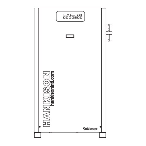
HPRplus Series with ColdWave™ Technology
Models:
HPRP 100, 125, 150, 200, 250, 300,
400, 500, 600, 750
CONTENTS
GENERAL SAFETY INFORMATION ......................... 2
RECEIVING, MOVING, AND UNPACKING ................ 2
1.0 INSTALLATION .................................................. 3
2.0 OPERATION ....................................................... 5
3.0 MAINTENANCE ................................................. 8
SIZING ...................................................................... 8
ENGINEERING DATA (Models 100-250) ................... 9
ENGINEERING DATA (Models 300-750) ................... 10
WIRING DIAGRAM (Models 100, 125 & 150) ........... 11
WIRING DIAGRAM (Model 750 - 460 VAC) .............. 13
DIMENSIONS / WEIGHTS ........................................ 14
PARTS LIST .............................................................. 17
WARRANTY .............................................................. 20
SERVICE DEPARTMENT: (724) 746-1100
REFRIGERATED
TYPE
COMPRESSED
AIR DRYERS
Advertisement
Table of Contents
Troubleshooting

Related Manuals for HANKISON HPRplus Series


Summary of Contents for HANKISON HPRplus Series
-
Page 1: Table Of Contents
Rev. A 5/06 18-2-675 5th Edition Internal Use Only 060519 INSTRUCTION MANUAL HPRplus Series with ColdWave™ Technology Models: HPRP 100, 125, 150, 200, 250, 300, 400, 500, 600, 750 CONTENTS REFRIGERATED GENERAL SAFETY INFORMATION ......2 RECEIVING, MOVING, AND UNPACKING ....2 TYPE 1.0 INSTALLATION .......... -
Page 2: General Safety Information
GENERAL SAFETY INFORMATION RECEIVING, MOVING, AND UNPACKING PRESSURIZED DEVICES: A. RECEIVING This equipment is a pressure containing This shipment has been thoroughly checked, packed and device. inspected before leaving our plant. It was received in good condition by the carrier and was so acknowledged. •... -
Page 3: Installation
IMPORTANT: READ PRIOR TO STARTING THIS EQUIPMENT 1.0 INSTALLATION 1.1 Location For typical placement in a compressed air system, see drawing. Air compressor intake – Locate air compressor so that contaminants potentially harmful to the dryer (e.g. ammonia) are not drawn into the air system. C. - Page 4 1.2 Mounting Models 100-150: Separator has a knurled fitting with flexible drain tubing Mount the dryer on a level solid surface. Holes are provided in attached. Be sure knurled fitting is tightened by turning the dryer base to permanently mount the dryer to the floor. counter-clockwise before operating dryer.
-
Page 5: Operation
B. Condensate enters the reservoir (1) through the inlet port. C. Program Monitor When the condensate level in the reservoir covers the Press and hold Program Mode button until Main Menu screen capacitance sensor, an electronic signal is sent to the solid appears. - Page 6 pressure increases. Solid particulate load in the CONTROL PANEL compressed air supply will determine frequency of service. Typically element changeout is recommended at least annually. Push ESC button to exit program mode NOTE: If after 60 seconds no button is pressed while in Program Mode, the audible alarm sounds for five (5) seconds.
- Page 7 D. Operating check points Check drain operation - push Drain (push-to-test) button to energize electric drain. A flow of condensate and/or Check that green Power-on light is illuminated air should be present at the drain outlet. Check that green Compressor-on light is illuminated if dryer is on in the manual mode or it is a scheduled on time Using the RS-232 port IMPORTANT: Refrigeration compressor must be restarted after...
-
Page 8: Maintenance
3.0 MAINTENANCE SIZING 3.1 Condenser coil – Clean off accumulated dust and dirt Determining dryer capacity at actual operating conditions monthly. To determine the maximum inlet flow capacity of a dryer at various operating conditions, multiply the rated capacity from 3.2 Moisture separator –... -
Page 9: Engineering Data (Models 100-250)
ENGINEERING DATA (Models 100-250) r i A y t i F ° t e l F ° t e l r i A r i a t e l ) r e ) g r t e l r i A r i a t e l ) r e... -
Page 10: Engineering Data (Models 300-750)
ENGINEERING DATA (Models 300-750) r i A y t i F ° t e l F ° t e l r i A r i a t e l ) r e ) g r t e l r i A r i a t e l ) r e... -
Page 11: Wiring Diagram (Models 100, 125 & 150)
WIRING DIAGRAM Models 100, 125 & 150 Model 100 - 120/230 VAC 120 VAC POWER CORD SUPPLIED 230 VAC CUSTOMER SUPPLIED COMPRESSOR HARNESS OVERLOAD POWER ON PILOT LIGHT CAPACITOR MTR1 COMPRESSOR START RELAY GROUND STUD FAN 1 HARNESS FPS 1 FAN 1 MTR2 Models 125/150 - 120/230 VAC... -
Page 12: Wiring Diagram (Models 200-600 - 460 Vac)
WIRING DIAGRAM Models 200-600 - 460 VAC 460 VAC 3 PHASE 60 Hz FROM LINE 21 L1 L2 L3 TB1 L1 L2 L3 COMPRESSOR HARNESS CONT 1 COMPRESSOR MTR1 H4 H3 REF SHEET 01 LINE 20 208V REF SHEET 02 LINE 10 230V REF SHEET 02 LINE 11 400V... -
Page 13: Wiring Diagram (Model 750 - 460 Vac)
WIRING DIAGRAM Model 750 - 460 VAC 460 VAC 3 PHASE 60 Hz FROM LINE 21 TB1 L1 DISCONNECT SWITCH COMPRESSOR HARNESS CONT 1 MTR1 COMPRESSOR H4 H3 REF SHEET 01 LINE 20 208V REF SHEET 02 LINE 10 230V REF SHEET 02 LINE 11 400V FAN 1 HARNESS... -
Page 14: Dimensions / Weights
DIMENSIONS / WEIGHTS Dimensions (inches) Model 37.56 37.56 37.56 38.60 38.60 45.38 45.38 58.06 58.06 58.06 25.62 25.62 25.62 32.15 32.15 32.15 32.15 32.15 32.15 32.15 1.63 1.63 1.63 1.88 1.88 2.63 2.63 2.77 2.77 2.77 23.62 23.62 23.62 30.15 30.15 30.15 30.15... -
Page 15: Troubleshooting Guide (Models 100-150)
TROUBLESHOOTING GUIDE (Models 100-150) SYMPTOM POSSIBLE CAUSE(S) CORRECTIVE ACTION A) Water downstream of dryer 1. Residual free moisture remaining in Blow out system with dry air downstream pipelines 2. Air bypass system is open Check valve positions 3. Inlet and Outlet connections are reversed Check for correct connection 4. -
Page 16: Troubleshooting Guide (Models 200-750)
TROUBLESHOOTING GUIDE (Models 200-750) SYMPTOM POSSIBLE CAUSE(S) CORRECTIVE ACTION A) Water downstream of dryer 1. Residual free moisture remaining in 1. Blow out system with dry air downstream pipelines 2. Air bypass system is open 2. Check valve positions 3. Inlet and Outlet connections are reversed 3. -
Page 17: Parts List
PARTS LIST t i n ) y l t i c c t i a i l t n i c t i i g i l a t t i n ) y l c t i c t i c t i c t i t l i... - Page 18 NOTES...
- Page 19 NOTES...
-
Page 20: Warranty
IS RETURNED TO THE FACTORY OR IN-WARRANTY REPAIRS ARE MADE. SERVICE DEPARTMENT: (724) 746-1100 SPX Dehydration & Process Filtration 1000 Philadelphia Street Canonsburg, PA 15317-1700 U.S.A. Phone: 724-745-1555 Fax: 724-745-6040 • Email: hankison.service dehydration.spx.com www.hankisonintl.com © 2006 SPX Corporation. All rights reserved. 3/03 Inv# 000 000...