Table of Contents
Advertisement
Available languages
Available languages
7610.719.3B
INSTRUCTION MANUAL
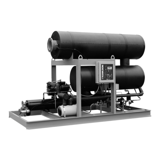
H Series
Contents
GENERAL SAFETY INFORMATION ...............................
RECEIVING, STORING, MOVING, UNPACKING
1.0 DESCRIPTION ...........................................................
2.0 INSTALLATION .........................................................
2.1 Location ..............................................................
2.2 Position in the compressed air system ...............
2.3 Mounting .............................................................
2.4 Piping ..................................................................
2.5 Electrical .............................................................
2.6 Air-Cooled Models ..............................................
2.7 Compressor tiedown nuts -
7 1/2 and 10 horsepower units only ....................
3.0 OPERATION ...............................................................
3.1 Start-up and Shut down Procedures ...................
3.2 Operational Sequence ........................................
3.3 Fault Conditions .................................................. 10
3.4 Lights and Gauges .............................................. 10
3.5 Operational Check Points ................................... 10
4.0 MAINTENANCE .......................................................... 11
4.1 Separator/Filter Sleeve Replacement ................. 11
4.2 Air-Cooled Condenser - Special Instructions ...... 12
4.3 Water-Cooled Condenser - Special Instructions 12
Cooling Water Requirements ..................................... 15
4.5 Condensate Drains - Electrically Operated ......... 17
TROUBLE SHOOTING ..................................................... 18
WARRANTY ..................................................................... 20
2
3
4
4
4
4
4
4
5
5
6
6
8
SERVICE DEPARTMENT: (724) 746-1100
REFRIGERATED
TYPE
COMPRESSED
AIR DRYERS
®
E
N
G
L
I
S
H
E
S
P
A
Ñ
O
L
1
Advertisement
Chapters
Table of Contents
Troubleshooting

Related Manuals for HANKISON H Series


Summary of Contents for HANKISON H Series
-
Page 1: Table Of Contents
7610.719.3B INSTRUCTION MANUAL ® H Series Contents GENERAL SAFETY INFORMATION ....... RECEIVING, STORING, MOVING, UNPACKING 1.0 DESCRIPTION ............2.0 INSTALLATION ............2.1 Location .............. 2.2 Position in the compressed air system ....2.3 Mounting ............. 2.4 Piping ..............2.5 Electrical ............. -
Page 2: General Safety Information
GENERAL SAFETY INFORMATION 1. PRESSURIZED DEVICES: This equipment is a pressure containing device • Do not exceed maximum operating pressure as shown on equipment serial number tag. • Make sure equipment is depressurized before working on or disassembling it for servicing. •... - Page 3 1.0 DESCRIPTION B. Operation Compressed air, saturated with water vapor, enters the dryer and is precooled by the outgoinq refriger- A. Function ated air in an air-to-air heat exchanger. Precooling Refrigerated type compressed air dryers reduce the removes some of the heat load from the incoming moisture content in compressed air by lowering the air allowing the use of a more efficient refrigeration air temperature causing water vapor to condense...
-
Page 4: Installation
B. Holes are provided in the dryer base to permanently 2.0 Installation mount it to a level solid floor. Ensure the dryer is level 2.1 Location by grouting, if necessary. The structural steel base is of an open design to facilitate cleaning and washing A. -
Page 5: Air-Cooled Models
Air-Cooled Models with Integral Condenser (Optional) Air Inlet Cooling Water Cooling Water Air Outlet Inlet Outlet Control Panel Condensate Electrical Drain Enclosure Connection SIDE VIEW FRONT VIEW A. Electrical entry is through electrical connection entry 2. After condenser is in place, run refrigeration lines hole in electrical enclosure. -
Page 6: Operation
2. Turn Stand-by/Auto Selector Switch to AUTO position. 3.0 Operation 3.1 Start-up and Shut down Procedures a. If SYSTEM ENABLED is displayed, dryer will automati- cally pump down before valves open and PREPAR- A. Pre-start-up Procedure ING TO RUN followed by DRYER RUNNING or COMP After making sure Master switch is OFF (Pushed in), LOADING is displayed. - Page 7 E. Start-Up Procedure - (Master switch on; dryer in Stand- 1. Turn Stand-by/Auto selector switch to AUTO. by mode.) 2. Allow at least 15 minutes of dryer operation before POWER TO THE DRYER MUST BE ENER- flowing compressed air through dryer. GIZED (POWER ON LIGHT ILLUMINATED) TWENTY-FOUR (24) HOURS BEFORE START-UP OF THE REFRIGERATION 3.
- Page 8 Operator Interface Display Condition Display Message Dryer energized; Master Switch Off DRYER ENERGIZED Dryer energized; Master Switch On STANDBY or SYSTEM ENABLED Status Stand-by Selected Dryer will pump down if suction pressure is high (indicated by "DRYER PUMPING DOWN") followed by "STAND-BY"...
- Page 9 Consult Factory For Wiring Schematic...
-
Page 10: Fault Conditions
3. CHECK SEPARATOR: Optional - Indicates pressure drop 3.3 Fault Conditions across dryer exceeds set point. NOTE: Clear fault messages by selecting fault message with up down arrow keys and pressing ENTER on the 4. HI INLET AIR TEMP: Optional - Indicates inlet air tem- operator interface. -
Page 11: Maintenance
b. Starting from outside (cartridges closest to vessel 4.0 Maintenance wall) screw separator/filter cartridge(s) (1) into inlet 4.1 Separator/Filter Sleeve Replacement manifold connection(s). A cone in the manifold will guide the cartridge bolt into the female threads. It A. When to replace Filter Sleeves is only necessary to finger tighten the cartridge to At rated flow conditions, when removing liquids, ensure the seal. - Page 12 4.2 Air-Cooled Refrigerant Condensers - Special 4.3 Water-Cooled Refrigerant Condenser - Special Instructions Instructions (Cleanable shell and tube type) A. The coil of the condensing section must be kept clean A. Water tubes should normally be mechanically cleaned to maintain refrigeration capacity. Monthly, or as periodically to assure optimum condenser efficiency.
- Page 13 h. Fully opened compressor discharge service valve: c. Algae or slime can usually be controlled by means Check to see that it is closed two (2) complete of an intermittent or batch treatment to shock the turns. See 3.0 Operation, Section 3.1.A.2.C "Open- organisms.
- Page 14 When using a cleaning tool, keep the inside of the (3) Close the condenser water shut-off valves tube wet, and move the tool slowly from one end adjacent to the unit. to the other while rotating it at a moderate speed. A hand drill brace is recommended.
-
Page 15: Cooling Water Requirements
Cooling Water Requirements 38 ° F P.D.P 50 ° F P.D.P Max. Refrig. Cooling Cooling Max. Refrig. Cooling Cooling Capacity Water Flow Water Capacity Water Flow Water Rate @ 85 ° F Rate @ 85 ° F Nominal Water Valve (BTU/HR) Pressure (BTU/HR) -
Page 16: Condensate Drains - Pneumatically Operated
B. Disassemble and service at least once a year. NOTE: 4.4 Condensate Drains - Pneumatically Operated Before starting the servicing procedure, make sure you have a repair parts kit on hand. A. Monthly- Flush out accumulated sludge and dirt by opening manual drain valves. -
Page 17: Condensate Drains - Electrically Operated
m. Place seal ring retainer (24) into bottom shell 4.5 Condensate drains - Electrically Operated assembly (26) making sure that end of float arm assembly with counterweight (20) is positioned in A. Monthly - Flush out accumulated sludge and dirt by open area of seal ring retainer. -
Page 18: Trouble Shooting
TROUBLE SHOOTING GUIDE SYMPTOM / FAULT POSSIBLE CAUSES CORRECTIVE ACTION Compressor stopped because 1. Faulty high pressure transducer (PT200) Check pressure reading, calibrate/ of high head pressure replace. (Consult factory for calibration) "HIGH REFRIG PRESS" 2. Refrigerant overcharge Reclaim excess refrigerant. 3. -
Page 19: Trouble Shooting Guide
TROUBLE SHOOTING GUIDE SYMPTOM / FAULT POSSIBLE CAUSES CORRECTIVE ACTION System Noise 1. Unit foundation improperly isolated. Isolate foundation. 2. Improper support or isolation of piping. Use correct piping techniques, and support piping with suitable hangers. 3. Slugging due to refrigerant feed back. Check expansion valve setting;... -
Page 20: Warranty
RETURNED TO THE FACTORY OR IN-WARRANTY REPAIRS ARE MADE. SERVICE DEPARTMENT: (724) 746-1100 SPX Air Treatment 1000 Philadelphia Street Canonsburg, PA 15317-1700 U.S.A. Phone: 724-745-1555 Fax: 724-745-6040 • Email: hankison.service airtreatment.spx.com www.hankisonintl.com © 2006 SPX Corporation. All rights reserved. 3/03 Inv# 000 000... - Page 21 7610.719.3B MANUAL DE INSTRUCCIONES ® Serie H Contenido INFORMACION GENERAL DE SEGURIDAD ....2 RECEPCION, ALMACENAJE, TRANSPORTE, Y DESEMPACADO ..............2 1.0 DESCRIPCION ............3 2.0 INSTALACION ............. 4 2.1 Localización ............4 2.2 Ubicación dentro del sistema de aire comprimido ............ 4 2.3 Montaje ..............
-
Page 22: Informacion General De Seguridad
INFORMACION GENERAL DE SEGURIDAD 1. RECIPIENTE SUJETO A PRESION: Este equipo es un recipiente sujeto a presión • No se exceda la presión máxima de operación mostrada en la placa de identificación del equipo. • Asegúrese que el equipo esté despresurizado antes de realizar cualquier servicio. •... -
Page 23: Descripcion
1.0 Descripción del Equipo B. Operación El aire comprimido, saturado con vapor de agua, entra al secador donde es preenfriado por el aire frío que A. Función sale del intercambiador térmico aire/refrigerante. El Los secadores de aire comprimido tipo refrigerativo preenfriamiento remueve algo de la carga térmica del reducen el contenido de humedad en el aire aire de entrada, permitiendo usar un condensador de... -
Page 24: Instalacion
B. El secador tiene perforaciones en su base para fijarlo 2.0 Instalación permanentemente al suelo, previamente nivelado y firme. 2.1 Localización Asegúrese que el secador esté perfectamente bien nivelado y si es necesario, instale calzas en la base. La La mejor ubicación para instalar el secador es base estructural de acero es de un diseño abierto que cualquier área bien ventilada y moderadamente facilita la limpieza y el lavado de la unidad. -
Page 25: Modelos Enfriados Por Aire
Modelos Enfriados por Aire con Condensador Integralmente Montado (Opcional) Entrada de Aire Entrada de Agua Salida de Agua Salida de de Enfriamiento de Enfriamiento Aire Panel de Control Conexión de los Gabinete Drenes de Eléctrico Condensados VISTA LATERAL VISTA FRONTAL 2. -
Page 26: Operacion
1. Después de que el secador haya sido energizado por lo 3.0 Operación menos veinticuatro (24) horas antes, jale el interruptor 3.1 Procedimientos de Arranque Inicial y Apagado principal a la posición de encendido. El display del secador mostrará ya sea en espera "STAND BY" o sistema habilitado A. - Page 27 2. Presione el interruptor principal hasta la posición de EL SECADOR DEBERA ESTAR ENERGIZADO APAGADO). VEINTICUATRO (24) HORAS ANTES DEL ARRANQUE DEL NOTA: Excepto por razones de mantenimiento, deje el COMPRESOR DE REFRIGERACION. secador energizado para mantener el calentador del 1.
-
Page 28: Secuencia De Operación
Display de Interfase del Operador Condición Mensaje del Display Secador energizado; Interruptor Principal Apagado (OFF) DRYER ENERGIZED (Secador Energizado) Secador energizado; Interruptor Principal Encendido (ON) STAND BY o SYSTEM ENABLED (espera o sistema habilitado) Estado Seleccionado Modo de Espera (Stand-by) El secador automáticamente comenzará... - Page 29 Ñ Diagrama Eléctrico Típico 9 SP...
-
Page 30: Condiciones De Falla
ya que dañará el módulo requiriéndose reemplazar el 3.3 Condiciones de Falla compresor. NOTA: Elimine los mensajes de falla seleccionando el mensaje con las flechas y presione aceptar "ENTER" en la B. Fallas, Indicación Informativa interfase del operador. No se podrán borrar los mensajes 1. -
Page 31: Mantenimiento
7. Verifique que la lectura de presión en la succión (Suction a. Cubra las partes expuestas de las cuerdas de los Pressure) muestre una lectura correcta. Refiérase a la tornillos con algún antioxidante para prevenir la sección de información técnica. corrosión de las cuerdas del múltiple. -
Page 32: Especiales
lado de alta presión. 4.2 Condensador del Refrigerante Enfriado por 4.3 Condensador del Refrigerante Enfriado por Aire - Instrucciones Especiales Agua (modelo con tubos removibles) A. Los tubos del agua deben ser limpiados periódicamente A. El radiador del condensador debe ser limpiado para asegurar la eficiencia óptima del condensador. - Page 33 fábrica. lado de bajo pH (menos de 6.0). h. Válvula de servicio de descarga completamente c. La formación de algas o limo puede ser controlado abierta: verifique que después de estar por medio de tratamientos intermitentes o rutinarios completamente abierta se cierre dos (2) vueltas para matar a los organismos.
- Page 34 tienen una válvula de dren en la tapa de retorno. marcar el tubo de cobre. b. Desarmado Cuando utilice alguna herramienta de limpieza, mantenga húmeda la parte interior del tubo, y mueva Remueva las tuercas o tornillos, tapas y sellos de lentamente la herramienta de un lado al otro del ambos lados del condensador.
-
Page 35: De Enfriamiento
Requerimientos de Agua de Enfriamiento 38 ° F/3°C P.R.P 50 ° F/10°C P.R.P Capacidad Caída de Capacidad Flujo requerido Caída de Flujo requerido máxima presión del máxima sistema de agua de presión del de agua de enfriamiento a sistema de agua de refrigeración agua... -
Page 36: Trampa De Condensados - Operadas Neumáticamente
drenes manuales. B. Desármelas y repárelas por lo menos una vez al año. 4.4 Trampa de Condensados - Operadas Antes de iniciar el procedimiento de servicio, asegúrese Neumáticamente de tener a la mano las refacciones. A. Mensualmente - Elimine los sedimentos sólidos 1. -
Page 37: Eléctricamente
vaselina. 4.5 Drenes de Condensados - Operados l. Ensamble el cilindro (13) al cuerpo de la válvula Electricamente utilizando seis tornillos. Asegúrese que el orificio de alivio (38) en el cilindro no esté obstruido. Suba y baje A. Mensualmente - Elimine la suciedad y partículas el ensamble de la válvula para asegurarse que acumuladas abriendo la válvula manual del dren. -
Page 38: Guia En Caso De Fallas
GUIA EN CASO DE FALLAS SINTOMA CAUSAS PROBABLES ACCION CORRECTIVA El compresor se para por 1. Transductor de alta presión defectuoso (PT200) Verifique la lectura de presión, calibre/reemplace. alta presión de refrigerante (Consulte a planta para su calibración) "HIGH REFRIG PRESS" 2. - Page 39 GUIA EN CASO DE FALLAS SINTOMA CAUSAS PROBABLES ACCION CORRECTIVA Baja presión en la descarga Ajuste el regulador de flujo de agua o en las válvulas 1. Unidades enfriadas por agua - Flujo de agua excesivo de agua de 3" y 4" limpie la cabeza de potencia. a través del condensador Verifique/reemplace el interruptor del ventilador.
-
Page 40: Garantia
CUALQUIER REPARACION EN EL EQUIPO. DEPARTAMENTO DE SERVICIO: (724) 746-1100 SPX Air Treatment 1000 Philadelphia Street Canonsburg, PA 15317-1700 U.S.A. Phone: 724-745-1555 Fax: 724-745-6040 • Email: hankison.service airtreatment.spx.com www.hankisonintl.com © 2006 SPX Corporation. All rights reserved. 3/03 Inv# 000 000 20 SP...