Table of Contents
Advertisement
Quick Links
Advertisement
Table of Contents
Troubleshooting

Related Manuals for Canon iPF800 Series


Summary of Contents for Canon iPF800 Series
- Page 1 Service Manual iPF800 series Aug 13 2008...
- Page 3 Canon will release technical information as the need arises. In the event of major changes in the contents of this manual over a long or short period, Canon will issue a new edition of this manual.
- Page 4 Introduction Symbols Used This documentation uses the following symbols to indicate special information: Symbol Description Indicates an item of a non-specific nature, possibly classified as Note, Caution, or Warning. Indicates an item requiring care to avoid electric shocks. Indicates an item requiring care to avoid combustion (fire). Indicates an item prohibiting disassembly to avoid electric shocks or problems.
- Page 5 Introduction The following rules apply throughout this Service Manual: 1. Each chapter contains sections explaining the purpose of specific functions and the relationship between electrical and mechanical systems with refer- ence to the timing of operation. In the diagrams, represents the path of mechanical drive; where a signal name accompanies the symbol , the arrow indicates the direction of the electric signal.
-
Page 7: Table Of Contents
Contents Contents Chapter 1 PRODUCT DESCRIPTION 1.1 Product Overview ............................1- 1 1.1.1 Product Overview ..............................1- 1 1.1.2 Product Overview ..............................1- 3 1.2 Features ..............................1- 5 1.2.1 Features .................................. 1- 5 1.2.2 Features .................................. 1- 5 1.2.3 Printhead ................................. 1- 5 1.2.4 Ink tank .................................. - Page 8 Contents 1.7.3.5 Disposing of the Lithium Battery ............................1- 85 Chapter 2 TECHNICAL REFERENCE 2.1 Basic Operation Outline ..........................2- 1 2.1.1 Printer Diagram................................2- 1 2.1.2 Printer Diagram................................2- 2 2.1.3 Print Signal Sequence .............................2- 3 2.1.4 Print Driving ................................2- 4 2.2 Firmware ..............................
- Page 9 Contents 2.5.6 Others..................................2- 53 Chapter 3 INSTALLATION 3.1 Transporting the Printer ..........................3- 1 3.1.1 Transporting the Printer............................3- 1 3.1.1.1 Transporting the Printer ................................3- 1 3.1.2 Reinstalling the Printer ............................3- 13 3.1.2.1 Reinstalling the Printer................................3- 13 Chapter 4 DISASSEMBLY/REASSEMBLY 4.1 Service Parts ..............................4- 1 4.1.1 Service parts................................
- Page 10 Contents 6.1 Troubleshooting............................6- 1 6.1.1 Outline..................................6- 1 6.1.1.1 Outline of Troubleshooting............................... 6- 1 6.2 Location of Connectors and Pin Arrangement ................... 6- 1 6.2.1 Main controller PCB ..............................6- 1 6.2.2 Carriage relay PCB ..............................6- 11 6.2.3 Head relay PCB ..............................6- 16 6.3 Version Up..............................
-
Page 11: Chapter 1 Product Description
Chapter 1 PRODUCT DESCRIPTION... - Page 13 Contents Contents 1.1 Product Overview ................................1-1 1.1.1 Product Overview ..................................1-1 1.1.2 Product Overview ..................................1-3 1.2 Features ..................................1-5 1.2.1 Features ......................................1-5 1.2.2 Features ......................................1-5 1.2.3 Printhead ...................................... 1-5 1.2.4 Ink tank ......................................1-5 1.2.5 Cutter......................................1-7 1.2.6 Roll holder ....................................1-7 1.2.7 Stand ......................................
-
Page 15: Product Overview
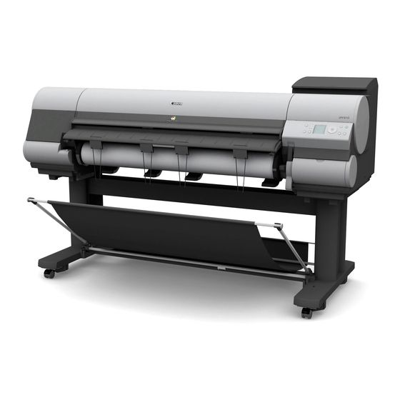
Chapter 1 1.1 Product Overview 1.1.1 Product Overview 0020-5395 iPF810 This printer is a large-format printer that prints in a maximum width of 44 inches with high-speed photographic picture quality. This printer is a stand-mounted type printer and is capable of output to either roll media or cut sheet. [10] [13] [12]... - Page 16 Chapter 1 F-1-2 T-1-2 Expansion Board Slot Madia Take-up Unit Connector Ethernet Connector Power Supply Connector USB Port Carrying Handles Manual Pocket Accessory Handles...
- Page 17 Chapter 1 1.1.2 Product Overview 0020-5396 iPF820 This printer is a large-format printer that prints in a maximum width of 44 inches with high-speed photographic picture quality. This printer is a stand-mounted type printer and is capable of output to either roll media or cut sheet. [12] [11] [15]...
- Page 18 Chapter 1 F-1-4 T-1-4 Expansion Board Slot Power Supply Connector Ethernet Connector Lower Roll Unit Connector USB Port Carrying Handles Manual Pocket Accessory Box...
-
Page 19: Features
Chapter 1 1.2 Features 1.2.1 Features 0020-5397 iPF820 - Media pass in widths up to 44 inches (1117.6 mm). - Large ink tanks save the need for their replacement. - Uninterrupted printing from subtanks. - BK and MBK inks are loaded concurrently to eliminate the need for their replacement. - Durability will be added by maintenance kit. - Page 20 Chapter 1 Ink tanks are disposable. An ink tank should be replaced when an ink tank replacement prompt message appears or when six months expire after the date of initial unpacking, whichever occurs earlier. To install ink tanks, open the right cover of the printer. Ink tanks are furnished with a notch for preventing incorrect installation, which will allow the tanks to be installed at the position marked in the right color and nowhere else.
-
Page 21: Cutter
Chapter 1 1.2.5 Cutter 0020-5420 iPF810 / iPF820 The cutter attached to the cutter unit is a round cutter. F-1-7 1.2.6 Roll holder 0020-5421 iPF810 / iPF820 The roller holder accepts paper tubes having inside diameters of both 2 and 3 inches. It is furnished with attachments for 2- and 3-inch diameter paper tubes. The roll holder clamps the paper tube of a roll not exceeding 150 mm in outside diameter from the inside. -
Page 22: Stand
Chapter 1 1.2.7 Stand 0020-6040 iPF820 It is a stand that puts the printer. Equipped with casters so that the printer can be easily moved. F-1-12 1.2.8 Stand 0020-6038 iPF810 It is a stand that puts the printer. Equipped with casters so that the printer can be easily moved. F-1-13 1.2.9 Wheeled output stacker 0020-5422... -
Page 23: Media Take-Up Unit
Chapter 1 F-1-14 T-1-5 Basket Basket foot stand Basket eject guide Stopper 1.2.10 Media take-up unit 0020-5423 iPF810 Media take-up unit The media take-up unit takes up roll media, ranging in width from 17 to 44 inches, on a 2 or 3-inch paper tube in roll form after they are printed by the host computer. Taking up begins automatically when a sensor attached to the bottom of the stand detects a roll delivered after printing falling down due to the weight of a weight roller. - Page 24 Chapter 1 Weight This weight consists of weight roll(7 pcs.)[1], weight flange(2 sets)[2] and weight joint[3]. F-1-16 1-10...
-
Page 25: Hard Disk Drive
Chapter 1 1.2.11 Hard disk drive 0017-8472 iPF810 / iPF820 Each print job received from the host computer is saved to the 80GB hard disk drive(serial ATA connection) attached to the printer, so the printer can print the job repeatedly as needed, without having to wait for its retransmission from the host computer. Saving print jobs will offer the following benefits: - Eased computer workload A print job may be automatically preserved to the hard disk when printing or may be preserved to the hard disk without printing. -
Page 26: Consumables
Chapter 1 1.2.13 Consumables 0020-5424 iPF810 / iPF820 Printhead The expendable printhead is the same as the one that comes with the printer. F-1-18 Ink tanks Expendable ink tanks are available in five colors: mat black, black, cyan, magenta and yellow. Each is further available in two capacities: 300ml and 700ml. All ink tanks are usable for six months after unpacking. -
Page 27: Product Specifications
Chapter 1 1.3 Product Specifications 1.3.1 Product Specifications 0020-5426 iPF820 Type Bubble jet large-sized paper printer (stand model) Feeding system Roll media: Upper roll/Lower roll (front loading) Cut sheet: Paper tray (front loading) Feeding capacity - Roll media 2 roll madia Outer diameter of roll: 150 mm or less - Cut sheet 1 sheet... - Page 28 Chapter 1 Detection functions (Ink passage Ink tank presence/absence detection: Yes system) Remaining ink level detection: Yes Maintenance cartridge presence/absence detection: Yes Used ink tank full detection: Yes Valve open/closed detection: Yes Detection functions (Carriage Printhead presence/absence detection: Yes system) Carriage position detection: Yes Carriage home position detection: Yes Printhead fixer lever open/closed detection: Yes...
-
Page 29: Detailed Specifications
Chapter 1 Printing recommendation area Internal area, excluding a 20-mm top margin, a 23-mm bottom margin (Cut sheet) and 5-mm left and right margins. Borderless printing * Roll media only width: 254mm(10"), 355.6mm(14"), 431.8mm(17"), 515mm, 594mm, 609.6mm(24"), 841mm, 914.4mm(36"), 1030mm, 1066.8mm(42") Memory 384MB Increase of memory: none... - Page 30 Chapter 1 T-1-7 Print Print Print- Used BK Media Type Print Priority Printing Direction Resolution Quality Pass (dpi) Plain Paper/ Plain Paper/Recycled Paper Office Document Standard Bi-directional 1200x1200 Recycled Paper Line Document/ Draft Bi-directional 1200x1200 Text Standard Bi-directional 1200x1200 Image Draft Bi-directional 1200x1200...
- Page 31 Chapter 1 Print Print Print- Used BK Media Type Print Priority Printing Direction Resolution Quality Pass (dpi) Coated Paper Coated Paper Image Standard Bi-directional 1200x1200 High Bi-directional 2400x1200 Highest Bi-directional 2400x1200 Heavyweight Coated Paper Image Standard Bi-directional 1200x1200 High Bi-directional 2400x1200 Highest Bi-directional...
- Page 32 Chapter 1 Print Print Print- Used BK Media Type Print Priority Printing Direction Resolution Quality Pass (dpi) Photo Paper Glossy Photo Paper Image Standard Bi-directional 1200x1200 High Bi-directional 2400x1200 Highest Bi-directional 2400x1200 Semi-Glossy Photo Paper Image Standard Bi-directional 1200x1200 High Bi-directional 2400x1200 Highest...
- Page 33 Chapter 1 Print Print Print- Used BK Media Type Print Priority Printing Direction Resolution Quality Pass (dpi) Art Paper Fine Art Photo Image Standard Bi-directional 1200x1200 High Bi-directional 2400x1200 Highest Bi-directional 2400x1200 Fine Art Heavyweight Photo Image Standard Bi-directional 1200x1200 High Bi-directional 2400x1200...
- Page 34 Chapter 1 Print Print Print- Used BK Media Type Print Priority Printing Direction Resolution Quality Pass (dpi) Matt Film Scrim Banner 370g Image Standard Bi-directional 1200x1200 Paper High Bi-directional 2400x1200 Highest Bi-directional 2400x1200 Adhesive Matt Stretch Vinyl Image Standard Bi-directional 1200x1200 High Bi-directional...
- Page 35 Chapter 1 Print Print Print- Used BK Media Type Print Priority Printing Direction Resolution Quality Pass (dpi) SPECIAL SPECIAL 1 Image Standard Bi-directional 1200x1200 High Bi-directional 2400x1200 Highest Bi-directional 2400x1200 SPECIAL 2 Image Standard Bi-directional 1200x1200 High Bi-directional 2400x1200 Highest Bi-directional 2400x1200 SPECIAL 3...
-
Page 36: Interface Specifications
Chapter 1 1.4.2 Interface Specifications 0013-8837 iPF810 / iPF820 a. USB (standard) (1) Interface type USB 2.0, Full speed (12 Mbits/sec), Hi-speed (480 Mbits/sec) (2) Data transfer system Control transfer Bulk transfer (3) Signal level Compliant with the USB standard. (4) Interface cable Twisted-pair shielded cable, 5.0 m max. -
Page 37: Names And Functions Of Components
Chapter 1 1.5 Names and Functions of Components 1.5.1 Front 0020-5443 iPF820 [12] [11] [15] [12] [17] [10] [13] [16] [14] [17] [18] [19] F-1-21 [1] Upper cover Open this cover to mount a printhead, load paper or remove per jammed jams inside the printer. [2] Ejection guides Allow printed material to be ejected. - Page 38 Chapter 1 Hold this lever to pull out the lower roll unit. 1-24...
-
Page 39: Front
Chapter 1 1.5.2 Front 0020-5447 iPF810 [10] [13] [12] [16] [13] [19] [5] [14] [17] [18] [11] [15] [19] [20] F-1-22 [1] Upper cover Open this cover to mount a printhead, load paper or remove per jammed jams inside the printer. [2] Ejection guides Allow printed material to be ejected. -
Page 40: Rear
Chapter 1 1.5.3 Rear 0020-5448 iPF820 F-1-23 [1] Expansion board slot Mount an IEEE1394 (FireWire) Expansion board (option) into this slot. [2] Ethernet connector Insert an Ethernet cable into this connector. A lamp will turn on if the Ethernet cable is connected properly and the printer is ready to communicate. [3] USB port Insert a USB cable into this port. - Page 41 Chapter 1 1.5.4 Rear 0020-5451 iPF810 F-1-24 [1] Expansion board slot Mount an IEEE1394 (FireWire) Expansion board (option) into this slot. [2] Ethernet connector Insert an Ethernet cable into this connector. A lamp will turn on if the Ethernet cable is connected properly and the printer is ready to communicate. [3] USB port Insert a USB cable into this port.
-
Page 42: Top Cover (Inside)
Chapter 1 1.5.5 Top Cover (Inside) 0020-5454 iPF810 / iPF820 [10] [13] [11] [12] F-1-25 [1] Upper cover roller Allows paper to be ejected by suppressing its loosing. [2] Registration line Load paper to fit to this line. [3] Carriage Drives the printhead. -
Page 43: Carriage
Chapter 1 1.5.6 Carriage 0020-5456 iPF810 / iPF820 F-1-26 [1] Printhead fixer cover Clamps the printhead. [2] Printhead A principal part that houses nozzles. [3] Printhead fixer lever Locks the printhead fixer cover. [4] Shaft cleaner Keeps the carriage shaft clean. [5] Slant adjustment lever Makes fine-adjustments with the misregistration of ruled lines printed. -
Page 44: Basic Operation
Chapter 1 1.6 Basic Operation 1.6.1 Operation Panel 0012-6277 iPF810 / iPF820 This section explains the functions of the buttons and the meanings of the LEDs on the operation panel. [19] [18] [17] [16] [15] [14] [10] [11] [12] [13] F-1-28 [1] Message lamp On: Indicates that a warning message is on display. -
Page 45: Main Menu
Chapter 1 1.6.2 Main Menu 0020-5459 iPF810 The printer has a Main menu which includes a menu related to maintenance such as adjustment of ink ejection position of each nozzle and head cleaning, a menu related to printing settings such as auto cutting and ink drying time, and a menu related to parameters such as a message language. 1. - Page 46 Chapter 1 2. Main Menu The structure of the main menu is as follows. T-1-8 First Level Second Level Third Level Fourth Level Fifth Level [Paper Cut](*1) [No]* [Yes] [Rep. Ink Tank] [No]* [Yes] [Head Cleaning] [Head Cleaning A]* [Head Cleaning B] [Auto Feed](*13) [No]* [Yes]...
- Page 47 Chapter 1 T-1-9 First Level Second Level Third Level Fourth Level Fifth Level [Media Menu] [Cas Paper Type] [FineArt Txtr](*5) [FineArt Wtrclr](*5) [FineArtBlockP](*5) [Canvas Matte2](*5) [JPN Paper Washi](*5) [Colored Coated](*5) [CAD Trace Paper](*5) [CAD Matte Film](*5) [CAD Clear Film](*5) [Special #] # Here, the number is 1 to 10 (*5) [Roll Media Type] [Plain Paper](*5)
- Page 48 Chapter 1 T-1-10 First Level Second Level Third Level Fourth Level Fifth Level [Media Menu] [Roll Media Type] [Proofing Paper](*5) [News Proof 1](*5) [News Proof 2](*5) [FineArt Photo](*5) [FneArt HW Photo](*5) [FineArt Txtr](*5) [FineArt Wtrclr](*5) [FineArtBlockP](*5) [Canvas Matte2](*5) [JPN Paper Washi](*5) [Colored Coated](*5) [CAD Trace Paper](*5) [CAD Matte Film](*5)
- Page 49 Chapter 1 T-1-11 First Level Second Level Third Level Fourth Level Fifth Level [Paper Details] (The paper type is [Skew Check Lv.] [Standard] displayed here.) (*5) [Loose] [Off] [VacuumStrngth] [Automatic]* [Strongest] [Strong] [Standard] [Weak] [Weakest] [Width Detection] [Off] [On] [NearEnd RollMrgn] [3mm] [20mm] [Cut Speed]...
- Page 50 Chapter 1 T-1-12 First Level Second Level Third Level Fourth Level Fifth Level [GL2 Settings] [Color Mode] [Monochrome] [Color(CAD)1] [Color(CAD)2] [Color(CAD)3] [Color(CAD)4] [Color(CAD)5] [Color(CAD)6] [Print Quality] [Draft] [Standard]* [High] [Print (Economy)] [Off]* [On] [Input Resolution] [600dpi]* [300dpi] [Paper Source] [Automatic]* [Roll Paper] [Cut Sheet] [Conserve Paper]...
- Page 51 Chapter 1 T-1-13 First Level Second Level Third Level Fourth Level Fifth Level [Adjust Printer] [Auto Head Adj.] [Standard Adj.] [No] [Yes] [Advanced Adj.] [No] [Yes] [Auto Print] [Off] [On]* [Manual Head Adj](*12) [No] [Yes] [Auto Band Adj.] [Standard Adj.] [No] [Yes] [Advanced Adj.]...
- Page 52 Chapter 1 T-1-14 First Level Second Level Third Level Fourth Level Fifth Level [Interface Setup] [TCP/IP] [Protocol](*4) [BOOTP] [On] [Off]* [RARP] [On] [Off]* [IP Setting](*14) [IP Address] 0.0.0.0 to 255.255.255.255 [Subnet Mask] 0.0.0.0 to 255.255.255.255 [Default G/W] 0.0.0.0 to 255.255.255.255 [NetWare] [NetWare] [On]...
- Page 53 Chapter 1 T-1-15 First Level Second Level Third Level Fourth Level Fifth Level [Maintenance] [Replace P.head] [No] [Yes] [Repl. S. Cleaner] [No] [Yes] [Move Printer] [Level 1]* [Level 2] [Level 3] [System Setup] [Warning] [Buzzer] [Off] [On]* [Detect Mismatch] [Pause] [Warning] [None]* [Skip Take-Up Err(*10)
- Page 54 Chapter 1 T-1-16 First Level Second Level Third Level Fourth Level Fifth Level [System Setup] [Length Unit] [meter]* [feet/inch] [Time Zone] [0: London (GMT)] [+1: Paris, Rome] [+2: Athens, Cairo] [+3: Moscow] [+4: Eerevan, Baku] [+5: Islamabad] [+6: Dacca] [+7: Bangkok] [+8: Hong Kong] [+9: Tokyo, Seoul] [+10: Canberra]...
- Page 55 Chapter 1 T-1-17 First Level Second Level Third Level Fourth Level Fifth Level [System Setup] [Language] [Japanese]* [English] [Francais] [Italiano] [Deutsch] [Espanol] [Pyccknn] [Chinese] [Korea] [Contrast Adj.] -4 to 4 [Reset PaprSetngs] [No] [Yes] [Erase HDD Data] [High Speed] [No] [Yes] [Secure High Spd.] [No]...
- Page 56 Chapter 1 3. Main menu during printing The structure of the main menu during printing is as follows. T-1-18 First Level Second Level Third Level Fourth Level Fifth Level [Menu Durng Prtng] [Head Cleaning] [Head Cleaning A] [Head Cleaning B] [Fine Band Adj.] -5 to 5 [Information]...
- Page 57 Chapter 1 4. Main Menu Settings Main menu items are described in the following tables. T-1-19 Setting Item Description, Instructions [Paper Cut] Displayed if a roll is loaded. Choose Yes to cut the roll at the current position. The paper will be fed, if necessary, so that the sheet is at least 10 cm (39.4 in.)long after the cut.
- Page 58 Chapter 1 [Paper Details] T-1-21 Setting Item Description, Instructions (The paper type is displayed [Roll DryingTime] Specify the time to wait for the ink to dry for each sheet. here.) [Scan Wait Time] Specify the time to wait for the ink to dry between each scan in bidirectional printing, in consideration of how quickly the ink dries.
- Page 59 Chapter 1 [Job Management] T-1-22 Setting Item Description, Instructions [Print Job] [Job List] (Choose a print [Delete] Delete the current job or queued jobs. job) [Preempt Jobs] Print the job first after the current print job is finished printing. [Stored Job] [Mailbox List] (Enter a password [Job List]-[Print]...
- Page 60 Print by the standard color. [Color(CAD)2] Print by the bright color. [Color(CAD)3] Print by the color emulated the Canon BJ-W3000/W3050. [Color(CAD)4] Print by the color emulated the HP Designjet 500/800. [Color(CAD)5] Print by the color emulated the HP Designjet 1000.
- Page 61 [Advanced Adj.] Choose this option when using paper other than genuine Canon paper, or paper for purposes other than checking output. Choose Yes to have the printer print and read a band adjustment test pattern for automatic adjustment of the feed amount.
- Page 62 Chapter 1 [Interface Setup] T-1-25 Setting Item Description, Instructions [EOP Timer] Specify the timeout period before cancellation of print jobs that cannot be received by the printer. [TCP/IP] [TCP/IP] Specify the TCP/IP protocol settings. To apply your changes, choose Register Setting. [IP Mode] Choose whether the printer IP address is configured automatically or a static IP address is entered manually.
- Page 63 Chapter 1 [System Setup] T-1-27 Setting Item Description, Instructions [Warning] [Buzzer] Set the buzzer. Choose On for the buzzer to sound once for warnings and three times for errors. [Detect Mismatch] Choose Warning for notification (display of a warning message) during printing if the paper type specified in the printer menu does not match the paper type in the printer driver.
- Page 64 Chapter 1 [Information] T-1-28 Setting Item Description, Instructions [System Info] [Version] [Firmware] Displays the version of the printer and firmware. [Boot] Displays the version of the boot ROM. [MIT] Displays the version of the MIT database format. [s/n] Displays the printer's serial number. [MAC] Displays the MAC address of the printer.
-
Page 65: Main Menu
Chapter 1 1.6.3 Main Menu 0020-5468 iPF820 The printer has a Main menu which includes a menu related to maintenance such as adjustment of ink ejection position of each nozzle and head cleaning, a menu related to printing settings such as auto cutting and ink drying time, and a menu related to parameters such as a message language. 1. - Page 66 Chapter 1 2. Main Menu The structure of the main menu is as follows. T-1-29 First Level Second Level Third Level Fourth Level Fifth Level [Paper Cut](*1) [No]* [Yes] [Rep. Ink Tank] [No]* [Yes] [Head Cleaning] [Head Cleaning A]* [Head Cleaning B] [Media Menu] [Cut Sheet Type] [Plain Paper](*5)
- Page 67 Chapter 1 T-1-30 First Level Second Level Third Level Fourth Level Fifth Level [Media Menu] [Cas Paper Type] [FineArt Txtr](*5) [FineArt Wtrclr](*5) [FineArtBlockP](*5) [Canvas Matte2](*5) [JPN Paper Washi](*5) [Colored Coated](*5) [CAD Trace Paper](*5) [CAD Matte Film](*5) [CAD Clear Film](*5) [Special #] # Here, the number is 1 to 10 (*5) [Roll1(Uppr) Type]/[Roll2 [Plain Paper](*5)
- Page 68 Chapter 1 T-1-31 First Level Second Level Third Level Fourth Level Fifth Level [Media Menu] [Roll1(Uppr) Type]/[Roll2 [Proofing Paper](*5) (Lwr) Type](*1, *2) [News Proof 1](*5) [News Proof 2](*5) [FineArt Photo](*5) [FneArt HW Photo](*5) [FineArt Txtr](*5) [FineArt Wtrclr](*5) [FineArtBlockP](*5) [Canvas Matte2](*5) [JPN Paper Washi](*5) [Colored Coated](*5) [CAD Trace Paper](*5)
- Page 69 Chapter 1 T-1-32 First Level Second Level Third Level Fourth Level Fifth Level [Paper Details] (The paper type is [Skew Check Lv.] [Standard] displayed here.) (*5) [Loose] [Off] [VacuumStrngth] [Automatic]* [Strongest] [Strong] [Standard] [Weak] [Weakest] [Width Detection] [Off] [On] [NearEnd RollMrgn] [3mm] [20mm] [Cut Speed]...
- Page 70 Chapter 1 T-1-33 First Level Second Level Third Level Fourth Level Fifth Level [GL2 Settings] [Color Mode] [Monochrome] [Color(CAD)1] [Color(CAD)2] [Color(CAD)3] [Color(CAD)4] [Color(CAD)5] [Color(CAD)6] [Print Quality] [Draft] [Standard]* [High] [Print (Economy)] [Off]* [On] [Input Resolution] [600dpi]* [300dpi] [Paper Source] [Automatic]* [Roll Paper] [Cut Sheet] [Conserve Paper]...
- Page 71 Chapter 1 T-1-34 First Level Second Level Third Level Fourth Level Fifth Level [Adjust Printer] [Auto Head Adj.] [Standard Adj.] [No] [Yes] [Advanced Adj.] [No] [Yes] [Auto Print] [Off] [On]* [Manual Head Adj](*12) [No] [Yes] [Auto Band Adj.] [Standard Adj.] [No] [Yes] [Advanced Adj.]...
- Page 72 Chapter 1 T-1-35 First Level Second Level Third Level Fourth Level Fifth Level [Interface Setup] [TCP/IP] [Protocol](*4) [BOOTP] [On] [Off]* [RARP] [On] [Off]* [IP Setting](*14) [IP Address] 0.0.0.0 to 255.255.255.255 [Subnet Mask] 0.0.0.0 to 255.255.255.255 [Default G/W] 0.0.0.0 to 255.255.255.255 [NetWare] [NetWare] [On]...
- Page 73 Chapter 1 T-1-36 First Level Second Level Third Level Fourth Level Fifth Level [Maintenance] [Replace P.head] [No] [Yes] [Repl. S. Cleaner] [No] [Yes] [Move Printer] [Level 1]* [Level 2] [Level 3] [System Setup] [Warning] [Buzzer] [Off] [On]* [Detect Mismatch] [Pause] [Warning] [None]* [Keep Media Size]...
- Page 74 Chapter 1 T-1-37 First Level Second Level Third Level Fourth Level Fifth Level [System Setup] [Length Unit] [meter]* [feet/inch] [Time Zone] [0: London (GMT)] [+1: Paris, Rome] [+2: Athens, Cairo] [+3: Moscow] [+4: Eerevan, Baku] [+5: Islamabad] [+6: Dacca] [+7: Bangkok] [+8: Hong Kong] [+9: Tokyo, Seoul] [+10: Canberra]...
- Page 75 Chapter 1 T-1-38 First Level Second Level Third Level Fourth Level Fifth Level [System Setup] [Language] [Japanese]* [English] [Francais] [Italiano] [Deutsch] [Espanol] [Pyccknn] [Chinese] [Korea] [Contrast Adj.] -4 to 4 [Reset PaprSetngs] [No] [Yes] [Erase HDD Data] [High Speed] [No] [Yes] [Secure High Spd.] [No]...
- Page 76 Chapter 1 3. Main menu during printing The structure of the main menu during printing is as follows. T-1-39 First Level Second Level Third Level Fourth Level Fifth Level [Menu Durng Prtng] [Head Cleaning] [Head Cleaning A] [Head Cleaning B] [Fine Band Adj.] -5 to 5 [Information]...
- Page 77 Chapter 1 4. Main Menu Settings Main menu items are described in the following tables. T-1-40 Setting Item Description, Instructions [Paper Cut] Displayed if a roll is loaded. Choose Yes to cut the roll at the current position. The paper will be fed, if necessary, so that the sheet is at least 10 cm (39.4 in.)long after the cut.
- Page 78 Chapter 1 [Paper Details] T-1-42 Setting Item Description, Instructions (The paper type is displayed [Roll DryingTime] Specify the time to wait for the ink to dry for each sheet. here.) [Scan Wait Time] Specify the time to wait for the ink to dry between each scan in bidirectional printing, in consideration of how quickly the ink dries.
- Page 79 Chapter 1 [Job Management] T-1-43 Setting Item Description, Instructions [Print Job] [Job List] (Choose a print [Delete] Delete the current job or queued jobs. job) [Preempt Jobs] Print the job first after the current print job is finished printing. [Stored Job] [Mailbox List] (Enter a password [Job List]-[Print]...
- Page 80 Print by the standard color. [Color(CAD)2] Print by the bright color. [Color(CAD)3] Print by the color emulated the Canon BJ-W3000/W3050. [Color(CAD)4] Print by the color emulated the HP Designjet 500/800. [Color(CAD)5] Print by the color emulated the HP Designjet 1000.
- Page 81 [Advanced Adj.] Choose this option when using paper other than genuine Canon paper, or paper for purposes other than checking output. Choose Yes to have the printer print and read a band adjustment test pattern for automatic adjustment of the feed amount.
- Page 82 Chapter 1 [Interface Setup] T-1-46 Setting Item Description, Instructions [EOP Timer] Specify the timeout period before cancellation of print jobs that cannot be received by the printer. [TCP/IP] [TCP/IP] Specify the TCP/IP protocol settings. To apply your changes, choose Register Setting. [IP Mode] Choose whether the printer IP address is configured automatically or a static IP address is entered manually.
- Page 83 Chapter 1 [System Setup] T-1-48 Setting Item Description, Instructions [Warning] [Buzzer] Set the buzzer. Choose On for the buzzer to sound once for warnings and three times for errors. [Detect Mismatch] Choose Warning for notification (display of a warning message) during printing if the paper type specified in the printer menu does not match the paper type in the printer driver.
- Page 84 Chapter 1 [Information] T-1-49 Setting Item Description, Instructions [System Info] [Version] [Firmware] Displays the version of the printer and firmware. [Boot] Displays the version of the boot ROM. [MIT] Displays the version of the MIT database format. [s/n] Displays the printer's serial number. [MAC] Displays the MAC address of the printer.
-
Page 85: Basket Unit
Chapter 1 1.6.4 Basket Unit 0017-9389 iPF810 The Basket Unit(output stacker) can be installed at four positions, as shown. F-1-29 F-1-30 [1] When storing printed documents on the Output Stacker, set it to this position. [2] When the Output Stacker is not used, set it to this position. [3] When printing on large and stiff sheets, or when the Media Take-up Unit is used, or when the Output Stacker is stored for long periods, lower it to this position for storage. - Page 86 Chapter 1 1) Lift the Basket Rod gently to release the lock, lower the stacker toward the front, and push it all the way back. F-1-31 2) Remove the front Basket Rod from the left and right Basket Rods, and remove the back Basket Rod and the black cord from the Rod Holder. F-1-32 1-72...
- Page 87 Chapter 1 3) Store the left and right Basket Rods. Next, remove the Rod Holder Adapter, leaving the Rod Holder attached, and put it in front of the printer. F-1-33 4) Pull out the Basket Hooks from the left and right side of the Ejection Guide. F-1-34 5) Attach the Basket Rod to the Basket Hooks so that the white tag of the Basket Cloth is on the left side.
- Page 88 Chapter 1 6) Form the Basket Cloth into a sloping shape to make it taut, and attach the middle Basket Rod to the Rod Holder. F-1-36 b. Stowing the Output Stacker Stow the Output Stacker if you will use the Media Take-up Unit or if you will not use the Output Stacker for an extended period. 1) Lift the front Basket Rod gently to release the lock, lower the stacker toward the front, and push it all the way back.
- Page 89 Chapter 1 2) Remove the front Basket Rod from the left and right Basket Rods. Roll up the Basket Cloth and put it at the back of the Bottom Stand Stay. F-1-38 F-1-39 Arrange the Basket Cloth and Basket Rod so they do not interfere with the Media Take-up Sensor. F-1-40 1-75...
- Page 90 Chapter 1 3) Push in the left and right Basket Rods toward the back all the way, until they stop. F-1-41 1-76...
-
Page 91: Safety And Precautions
Chapter 1 1.7 Safety and Precautions 1.7.1 Safety Precautions 1.7.1.1 Moving Parts 0020-5470 iPF810 / iPF820 Be careful not to get your hair, clothes, or accessories caught in the moving parts of the printer. These include the carriage unit activated by the carriage motor, carriage belt, ink tube and flexible cable; feed motor-driven feed roller and pinch roller; and purge motor-driven purge unit. -
Page 92: Adhesion Of Ink
Chapter 1 1.7.1.2 Adhesion of Ink 0020-5471 iPF810 / iPF820 1. Ink passages Be careful not to touch the ink passages of the printer or to allow ink to stain the workbench, hands, clothes or the printer under repair. The ink flows through the ink tank unit, carriage unit, purge unit, maintenance jet tray, borderless print ink groove, maintenance cartridge and the ink tubes that relay ink to each unit. - Page 93 Chapter 1 2. Ink mist Since the printhead prints by squirting ink onto the media, a minute amount of ink mist is generated in the printing unit during printing. The ink mist is collected in the printer by the airflow. However, uncollected ink mist may stain the platen unit, carriage unit, main rail unit, external unit, or purge unit. These stains may soil the print media or hands and clothes when servicing the printer, wipe them off carefully with a soft, well-wrung damp cloth.
-
Page 94: Electric Parts
Chapter 1 1.7.1.3 Electric Parts 0020-5474 iPF810 / iPF820 The electrical unit of the printer is activated when connected to the AC power supply. At the rear of the printer are the main controller, power supply, interface connector, and optional media take-up unit connector. The head relay PCB and carriage relay PCB are incorporated in the carriage unit, and the operation panel is located on the upper right cover. -
Page 95: Other Precautions
Chapter 1 1.7.2 Other Precautions 1.7.2.1 Printhead 0020-1924 iPF810 / iPF820 1. How to Handle the Printhead Do not open the printhead package until you are ready to install the head. When installing the printhead in the printer, hold the knob[1] and then remove the protective cap 1[2] and protective cap 2[3] in that order. Do not reattach the protective cap 2[3] to the printhead because the cap may damage the nozzles[4]. -
Page 96: Ink Tank
Chapter 1 If electrical units are powered with ink leaked onto them, the units may damage. Never connect the power cord when ink has leaded onto the electrical units. 1.7.2.2 Ink Tank 0012-6292 iPF810 / iPF820 1. Unpacking the Ink Tank Do not unpack the ink tank until you are ready to install it. -
Page 97: Handling The Printer
Chapter 1 1.7.2.3 Handling the Printer 0020-5475 iPF810 / iPF820 1. Precautions against Static Electricity Certain clothing may generate static electricity, causing an electrical charge to build up on your body. Such a charge can damage electrical devices or change their electrical characteristics. - Page 98 Chapter 1 3. Contact of Linear Scale/Carriage Shaft Please do not touch a linear scale and the carriage shaft when the inside of the top cover is opened, and execute maintenance. When touching a linear scale and the carriage shaft, it might cause defective movement of the carriage and a defective print. F-1-50 [1] Linear Scale [2] Carriage Shaft...
-
Page 99: Precautions When Servicing Printer
Chapter 1 1.7.3 Precautions When Servicing Printer 1.7.3.1 Notes on the Data Stored in the Printer 0013-5942 iPF810 / iPF820 This printer counts the print length, number of ink tank replacements, carriage driving time, number of cleaning operations, number of cutter operations, and so on and stores them in the main controller's EEPROM as a COUNTER in Service mode. - Page 100 Chapter 1 1-86...
-
Page 101: Chapter 2 Technical Reference
Chapter 2 TECHNICAL REFERENCE... - Page 103 Contents Contents 2.1 Basic Operation Outline..............................2-1 2.1.1 Printer Diagram.................................... 2-1 2.1.2 Printer Diagram.................................... 2-2 2.1.3 Print Signal Sequence .................................. 2-3 2.1.4 Print Driving ....................................2-4 2.2 Firmware ..................................2-6 2.2.1 Operation Sequence at Power-on..............................2-6 2.2.2 Operation Sequence at Power-off ..............................2-7 2.2.3 Print Control....................................
- Page 104 Contents 2.4.5 Motor Driver ....................................2-44 2.4.5.1 Media take-up PCB components .................................. 2-44 2.4.5.2 Lower roll unit PCB components ................................. 2-44 2.4.6 Maintenance Cartridge Relay PCB............................2-44 2.4.6.1 Maintenance cartridge relay PCB components............................. 2-44 2.4.7 Power Supply ..................................... 2-45 2.4.7.1 Power supply block diagram..................................2-45 2.5 Detection Functions with Sensors ..........................
-
Page 105: Basic Operation Outline
Chapter 2 2.1 Basic Operation Outline 2.1.1 Printer Diagram 0020-5476 iPF810 A printer diagram is shown below. Operation panel PCB Main controller PCB IC601-IC604 SO-DIMM SDRAM Maintenance cartridge relay PCB IC701/IC703 IC802 CN201 J1801 Maintenance cartridge EEPROM FLASH ROM Power supply PCB ROM PCB Ink tank IC803... -
Page 106: Printer Diagram
Chapter 2 2.1.2 Printer Diagram 0020-5477 iPF820 A printer diagram is shown below. Operation panel PCB Maintenance cartridge relay PCB Main controller PCB IC601-IC604 Maintenance cartridge SO-DIMM SDRAM ROM PCB Ink tank IC802 IC701/IC703 CN201 J1801 EEPROM FLASH ROM Power supply PCB Ink tank ROM PCB Ink detection sensor Sensors/Switches... -
Page 107: Print Signal Sequence
Chapter 2 2.1.3 Print Signal Sequence 0017-4696 iPF810 / iPF820 The signal sequence from when the printer receives the print signals until printing starts is shown in Figure. Image data Host computer Mask pattern data Heat pulse Printer driver Command data PCI bus Data bus Universal sirial bus... -
Page 108: Print Driving
Chapter 2 2.1.4 Print Driving 0013-5398 iPF810 / iPF820 Print and control signals are transferred via the carriage relay PCB and head relay PCB to the printheads to discharge inks from the nozzle assembly at printing. Each printhead has 12 trains of nozzles arranged in a zigzag pattern. This printer uses one printhead. - Page 109 Chapter 2 2. Print drive timing Each printhead houses 12 trains of nozzles, which share the same data transfer clock (Hx-CLK) and data latch pulses (Hx-LT). Even-numbered nozzle data (Hx-x-DATA-x-EV), odd-numbered nozzle data (Hx-x-DATA-x-OD) and the Heat Enable (Hx-x-HE-x) signal are generated for each nozzle train and controlled individually.
-
Page 110: Firmware
Chapter 2 2.2 Firmware 2.2.1 Operation Sequence at Power-on 0012-6310 iPF810 / iPF820 The sequence of printer operations, from power-on to transition to online mode, is flowcharted below. The printer takes less than 1 minute to initialize itself(*). * Excluding the times spent supplying inks and cleaning the printhead after leaving the printer for extended periods of time. Power Button ON Initialization of software Device/resource... -
Page 111: Operation Sequence At Power-Off
Chapter 2 2.2.2 Operation Sequence at Power-off 0012-6311 iPF810 / iPF820 Turning off the power switch cuts off the drive voltage supply, launching a firmware power-off sequence as shown below. If the power cord is disconnected from the wall outlet or the upper cover or any other cover is opend, the printer cancels the ongoing operation and shuts down immediately. -
Page 112: Print Control
Chapter 2 2.2.3 Print Control 0020-5482 iPF810 / iPF820 1. Print mode This printer is capable of fast, high-quality printing without blur and non-uniform density by changing the carriage operation, media feeding, other printing methods according to the selected media type, print quality, print data and so on. Printing is performed for each color using a maximum of 16 paths in each print mode according to the selected print quality. - Page 113 Chapter 2 T-2-2 Print Print Print- Used BK Media Type Print Priority Printing Direction Resolution Quality Pass (dpi) Plain Paper/ Plain Paper/Recycled Paper Office Document Standard Bi-directional 1200x1200 Recycled Paper Line Document/ Draft Bi-directional 1200x1200 Text Standard Bi-directional 1200x1200 Image Draft Bi-directional 1200x1200...
- Page 114 Chapter 2 Print Print Print- Used BK Media Type Print Priority Printing Direction Resolution Quality Pass (dpi) Coated Paper Coated Paper Image Standard Bi-directional 1200x1200 High Bi-directional 2400x1200 Highest Bi-directional 2400x1200 Heavyweight Coated Paper Image Standard Bi-directional 1200x1200 High Bi-directional 2400x1200 Highest Bi-directional...
- Page 115 Chapter 2 Print Print Print- Used BK Media Type Print Priority Printing Direction Resolution Quality Pass (dpi) Photo Paper Glossy Photo Paper Image Standard Bi-directional 1200x1200 High Bi-directional 2400x1200 Highest Bi-directional 2400x1200 Semi-Glossy Photo Paper Image Standard Bi-directional 1200x1200 High Bi-directional 2400x1200 Highest...
- Page 116 Chapter 2 Print Print Print- Used BK Media Type Print Priority Printing Direction Resolution Quality Pass (dpi) Art Paper Fine Art Photo Image Standard Bi-directional 1200x1200 High Bi-directional 2400x1200 Highest Bi-directional 2400x1200 Fine Art Heavyweight Photo Image Standard Bi-directional 1200x1200 High Bi-directional 2400x1200...
- Page 117 Chapter 2 Print Print Print- Used BK Media Type Print Priority Printing Direction Resolution Quality Pass (dpi) Matt Film Scrim Banner 370g Image Standard Bi-directional 1200x1200 Paper High Bi-directional 2400x1200 Highest Bi-directional 2400x1200 Adhesive Matt Stretch Vinyl Image Standard Bi-directional 1200x1200 High Bi-directional...
- Page 118 Chapter 2 Print Print Print- Used BK Media Type Print Priority Printing Direction Resolution Quality Pass (dpi) SPECIAL SPECIAL 1 Image Standard Bi-directional 1200x1200 High Bi-directional 2400x1200 Highest Bi-directional 2400x1200 SPECIAL 2 Image Standard Bi-directional 1200x1200 High Bi-directional 2400x1200 Highest Bi-directional 2400x1200 SPECIAL 3...
-
Page 119: Print Position Adjustment Function
Chapter 2 2.2.4 Print Position Adjustment Function 0012-6313 iPF810 / iPF820 This printer supports a print position adjust the vertical and horizontal print position and the bidirectional print position of the print head mounted on the carriage and the feedrate. Print position adjustment work in two modes: automatic adjustment, in which print position adjustment patterns printed are detected by a multi sensor attached to the lower left part of the carriage, and manual adjustment, in which print position adjustment patterns that are slightly modified from one another are printed, so that visually verified adjustment values can be set from the operation panel. - Page 120 Chapter 2 3) Job preservation Print jobs are in the common box, a place of temporary data storage, and in the personal box, a place of permanent data storage. Normal print jobs are stored in the common box as they are received. Due to the limited hard disk space available, jobs stored in the common box are deleted from the oldest one in sequence.
-
Page 121: Printer Mechanical System
Chapter 2 2.3 Printer Mechanical System 2.3.1 Outline 2.3.1.1 Outline 0020-5485 iPF810 / iPF820 The mechanical components of the printer can be broadly divided into an ink passage and a paper pass. The ink passage consists mainly of ink tank assembly [1] and a printhead mounted on carriage unit [2], purge assembly [3] and maintenance cartridge [4]. Its func- tions are to supply, circulate and suck inks and more. -
Page 122: Ink Passage
Chapter 2 2.3.2 Ink Passage 2.3.2.1 Ink Passage 2.3.2.1.1 Overview of Ink Passage 0020-5486 iPF810 / iPF820 The ink passage houses the ink tank, printhead, caps, maintenance jet tray, maintenance cartridge, waste ink collector, ink tubes interconnecting the mechanical units, suction pump driven mainly for sucking inks and so on. Its functions include supplying, circulating and sucking inks. The ink passage (per color) is schematically shown below, along with the ink flow. -
Page 123: Ink Tank Unit
Chapter 2 2.3.2.2 Ink Tank Unit 2.3.2.2.1 Structure of Ink Tank Unit 0020-5487 iPF810 / iPF820 a) Ink tanks The ink level in each ink tank is memorized in EEPROM attached to the tank and is detected as a dot count on the basis of the EEPROM information. When an electrode attached to a hollow needle detects no continuity, it displays a message reporting that the ink tank is nearly empty. - Page 124 Chapter 2 e) Subtank The subtank installed under each ink tank complements the work of the ink tank, agitating the ink in the tank. If the ink tank runs out of the ink while printing, the ink stored in the subtank is available, allowing the ink tank to be replaced without having to stop printing. f) Ink supply valves Located halfway between each subtank and the ink tube, the ink supply valve prevents ink leaks that may occur when the ink tube on the ink tank is released during replacement of the ink tank.
-
Page 125: Carriage Unit
Chapter 2 2.3.2.3 Carriage Unit 2.3.2.3.1 Functions of Carriage Unit 0020-5488 iPF810 / iPF820 a) Printhead mounting function The carriage, which fixes the printhead in position mechanically, is connected to the contact of the head relay PCB. b) Control function The carriage carries a carriage relay PCB, which relays drive signals from the main controller PCB, a head relay PCB,which relay printhead drive signals to print- head, a linear encoder, which generates print timing signals, and a multi sensor, which detects the width of paper and skews in it, adjusts is registration and head height. -
Page 126: Structure Of Carriage Unit
Chapter 2 2.3.2.3.2 Structure of Carriage Unit 0020-5492 iPF810 / iPF820 a) Printhead mount The printhead is secured to the carriage by the printhead fixer cover and the printhead fixer lever. When the printhead is secured to the carriage, the signal contact of the head relay PCB is pressed against that of the printhead to convey print signals. Further, the ink passage from the ink tanks is connected to the printhead via the ink tubes. - Page 127 Chapter 2 thereby varying the separation between the face of the printhead and the paper. The printhead height is detected from the lift cam sensor within the carriage and the distance of rotation of the lift motor. g) Multi sensor The multi sensor attached to the lower left part of the carriage consists of four LEDs (red, blue, green, infrared) and two light-receiving sensors to detect the leading edges and width of paper and skews in it, and to adjust its registration and head height.
-
Page 128: Printhead
Chapter 2 2.3.2.4 Printhead 2.3.2.4.1 Structure of Printhead 0013-8015 iPF810 / iPF820 Each printhead is an integrated assembly of six trains of nozzles. Capable of controlling each nozzle individually, each printhead implements discharge control for six colors by itself. a) Nozzle arrangement The nozzle assembly is formed of 1,280 nozzles arranged at 600-dpi intervals in a zigzag pattern, offering a total of 2,560 nozzles 1,200-dpi intervals. -
Page 129: Purge Unit
Chapter 2 2.3.2.5 Purge Unit 2.3.2.5.1 Functions of Purge Unit 0020-5700 iPF810 / iPF820 To maintain high print quality, the purge unit performs maintenance of the nozzles o the printhead. The purge unit supports a capping function, cleaning function, and ink supply function. a) Capping function The capping function presses the cap of the purge unit against the face plate on the nozzle section of the printhead to prevent nozzle drying and dust adhesion. - Page 130 Chapter 2 Cleaning operation timings are as follows. Consumption Printer status Cleaning operation (typ.)*1 Standby 168 hours elapsed capped Cleaning 1 (Normal Cleaning) At least 720 to 960 hours elapsed since the last session of Cleaning 2, 3, 6 or 10 (480 hours after Cleaning 6 (Normal initial installation) (strong) Cleaning)
-
Page 131: Structure Of Purge Unit
Chapter 2 2.3.2.5.2 Structure of Purge Unit 0020-5494 iPF810 / iPF820 a) Caps The caps cap the nozzle assembly in the left printhead during capping and cleaning. The part of the caps that comes into contact with the face plate of the nozzle assembly is made of rubber. - Page 132 Chapter 2 d) Pump The pump is a tube pump that pressurizes the ink tubes with rotating rollers to produce a negative pressure for sucking inks. Each individual tube is sequentially pressurized by two rotating rollers to control the rate of ink suction by a wide margin. The rate of rotation of the rotating pumps is controlled by driving the purge motor or the HP maintenance jet pump motor as the timing at which the rotating pumps rotate is detected by a pump cam sensor.
-
Page 133: Maintenance Cartridge
Chapter 2 2.3.2.6 Maintenance Cartridge 2.3.2.6.1 Maintenance Cartridge 0020-5497 iPF810 / iPF820 a) Maintenance cartridge The maintenance cartridge holds as much about 1000 mL of used inks. b) Used maintenance cartridge ink detection Used maintenance cartridge ink detection is monitored with regard to a dot count. When the quantity of the used ink reaches about 800 mL (80% of the cartridge capacity), the warning message "Check maint cartridge capacity"... -
Page 134: Air Flow
Chapter 2 2.3.2.7 Air Flow 2.3.2.7.1 Air flow 0020-5500 iPF810 / iPF820 This printer is provided with four fans: two mist fans for collecting ink mist, a suction fan for allowing paper to be sucked onto the platen and a BP maintenance jet suction fan for collecting idle discharges. -
Page 135: Paper Path
Chapter 2 2.3.3 Paper Path 2.3.3.1 Outline 2.3.3.1.1 Overview of Paper Path 0020-5503 iPF810 / iPF820 The paper pass comprises an upper roll media pick-up drive unit, a lower roll media pick-up drive unit, a feed roller, a pinch roller pressure drive unit that pressurizes and depressurizes the pinch roller, a roll holder drive unit that drives the roll holder and sensors that detect the transport status of paper to feed paper in three different ways, and transport and eject the paper. -
Page 136: Paper Path
Chapter 2 2.3.3.2 Paper Path 2.3.3.2.1 Structure of Pick-up/Feed Unit 0020-5505 iPF810 / iPF820 a) Roll media pick-up The components of the roll media pick-up consists include a pick-up roller driven by a roll media pick-up motor, a roller that follows the motion of the pick-up roller, a roll media pick-up roller clutch that controls the driving of the pick-up roller and a roll media pick-up cam clutch that controls the rise and fall of the roller. - Page 137 Chapter 2 Pinch roller pressure release shaft Pinch roller pressure detection sensor Pinch roller release detection sensor Sensor flag Down Pinch roller Pinch roller pressure clutch Pinch roller pressure motor Flapper solenoid:ON (During roll media loaded) Flapper solenoid:OFF (During cut sheet loaded) Route of roll media Route of cut sheet Flapper solenoid...
- Page 138 Chapter 2 f) Paper feed assembly The paper feed assembly consists of paper feeding mechanisms, such as a feed roller that is driven by the feed motor and a pinch roller unit that follows up the motion of the feed roller. Paper feeds horizontally under the printheads on the carriage as it is kept level on the platen to prevent cockling.
-
Page 139: Cutter Unit
Chapter 2 2.3.3.3 Cutter Unit 2.3.3.3.1 Structure of Cutter Unit 0020-5538 iPF810 / iPF820 When a roll media is used, the cutter unit cuts the leading end of the roll on loading and also cuts the roller on paper ejection. Whether cutting takes place or not depends on the relevant printer driver setting in the main menu. -
Page 140: Printer Electrical System
Chapter 2 2.4 Printer Electrical System 2.4.1 Outline 2.4.1.1 Overview 0020-5539 iPF820 The printer electrical system consists of the main controller PCB and lower roll unit PCB and power supply PCB and hard disk drive which are mounted on the back side of the printer, the carriage relay PCB, the head relay PCB, and printhead which are mounted in the carriage, the operation panel on the right upper cover and other electrical components such as sensors, and motors. - Page 141 Chapter 2 Power supply PCB Main controller PCB +26V generation function IC1501/IC1701 AC inlet IC1601-IC1603 +21.5V generation function Power supply control function BAT801 IC601-IC604 SO-DIMM Lithium battery SDRAM IC802 IC803 EEPROM Host computer Interface control function Network Board IC1201 Hard disk drive control function HDD controller Linear encoder Linear encoder detection function...
-
Page 142: Overview
Chapter 2 2.4.1.2 Overview 0020-5544 iPF810 The printer electrical system consists of the main controller PCB and media take-up relay PCB and power supply PCB and hard disk drive which are mounted on the back side of the printer, the carriage relay PCB, the head relay PCB, and printhead which are mounted in the carriage, the operation panel on the right upper cover and other electrical components such as sensors, and motors. - Page 143 Chapter 2 Power supply PCB Main controller PCB +26V generation function IC1501/IC1701 AC inlet IC1601-IC1603 +21.5V generation function Power supply control function BAT801 IC601-IC604 SO-DIMM Lithium battery SDRAM IC803 IC802 EEPROM Host computer Interface control function Network Board IC1201 Hard disk drive control function HDD controller Linear encoder Linear encoder detection function...
-
Page 144: Main Controller
Chapter 2 2.4.2 Main Controller 2.4.2.1 Main controller PCB components 0020-5546 iPF810 / iPF820 IC802 IC802 IC601 IC601 IC2802 IC2802 IC3100 IC3100 IC602 IC602 IC4101 IC4101 IC2700 IC2700 IC701 IC701 BAT801 BAT801 IC603 IC603 IC4501 IC4501 IC4601 IC4601 IC703 IC703 IC2900 IC2900 IC4602... - Page 145 Chapter 2 head EEPROM in addition to the on-board EEPROM. Clutch/Solenoid control function This function controls the clutches and solenoids based on the control signal from the ASIC. Motor control function This function controls the carriage motor, feed motor, valve motor, purge motor and lift motor based on the input signals from sensors. b) Driver IC (IC2700) This IC generates a HP maintenance jet pump motor control signal based on the control signal from the ASIC.
-
Page 146: Carriage Relay Pcb
Chapter 2 2.4.3 Carriage Relay PCB 2.4.3.1 Carriage relay PCB components 0020-5553 iPF810 / iPF820 F-2-31 a) Image data relay function This function relays the image data from the main controller PCB to the printhead. The function for processing image data is not supported. b) Sensor relay function This function relays the input signals from the multi sensor, printhead fixer lever sensor, and linear encoder to the main controller PCB. - Page 147 Chapter 2 This function relays the image data from the main controller PCB to the printhead. 2-43...
-
Page 148: Motor Driver
Chapter 2 2.4.5 Motor Driver 2.4.5.1 Media take-up PCB components 0014-2480 iPF810 IC104 F-2-33 a) Driver IC (IC104) Media take-up motor drive function This function controls the Media take-up motor based on the control signals from the main controller. Sensor relay function This function relays the input signals from the Media take-up paper detection sensor and Media take-up on/off sensor to the main controller PCB. -
Page 149: Power Supply
Chapter 2 2.4.7 Power Supply 2.4.7.1 Power supply block diagram 0012-6414 iPF810 / iPF820 AC inlet 100V to 240V Operation panel Main controller PCB Power supply DC power supply +32V Noize filter circuit POWER ON control circuit generation circuit Transformer +5V/+3.3V +5.1V Rectifying circuit... -
Page 150: Detection Functions With Sensors
Chapter 2 2.5 Detection Functions with Sensors 2.5.1 Sensors for covers 0020-5557 iPF810 / iPF820 Upper cover lock switch Pinch roller pressure release switch Ink tank cover switch Lower roll unit release detection switch F-2-37 Upper cover lock switch (L) / (R) The microswitch-based upper cover lock switches detect the open/closed states of the upper cover. -
Page 151: Ink Passage System
Chapter 2 2.5.2 Ink passage system 0020-5560 iPF810 / iPF820 Agitation cam sensor Valve open/closed detection sensor Pump cam sensor HP maintenance jet Pump encoder sensor pump encoder sensor Head management sensor F-2-38 Pump cam sensor As the cam rotates, it shields the sensor light of the photointerrupter-based pump cam sensor or allows it to be transmitted. the status of the purge unit, such as capped, suction, and wiping, is detected in a Combination of the status of detection by the pump cam sensor and the control of pump motor rotation by the pump encoder sensor. - Page 152 Chapter 2 Pump encoder sensor/HP maintenance jet pump encoder sensor The photointerrupter-based sensor reads slits in the encoder film of the Purge motor/HP maintenance jet pump motor and controls the amount of its rotaion accord- ingly. Slits Sensor F-2-40 Valve open/closed detection sensor The photointerrupter-based valve open/closed detection sensor detects the status of the valve.
-
Page 153: Carriage System
Chapter 2 2.5.3 Carriage system 0020-5567 iPF810 / iPF820 Linear encoder sensor Printhead fixer lever sensor Multi sensor Linear scale Carriage HP sensor Lift cam sensor F-2-43 Printhead fixer lever sensor The photointerrupter-type printhead fixer lever sensor detects the opening and closing of the printhead fixer lever. When the printhead fixer lever is closed, the sensor arm shields the sensor light, causing the sensor to detect the closed state of the printhead fixer lever. - Page 154 Chapter 2 The head temperature sensor detects the temperature of the printhead. The printhead temperature is transmitted to the main controller via the carriage relay PCB. The printhead temperature is used to help control the head drive and detect abnormal printhead temperatures. Printhead contact detection The printhead contact detects the status of printhead installation by electrical means.
-
Page 155: Paper Path System
Chapter 2 2.5.4 Paper path system 0020-5570 iPF810 / iPF820 Pinch roller release Feed roller detection sensor encoder sensor Feed roller HP sensor Media sensor Pinch roller pressure detection sensor Cutter HP sensor Cutter left position sensor Roll media width detection sensor (Lower roll media width detection sensor) Roll media pick-up roller paper detection sensor... - Page 156 Chapter 2 The photointerrupter-type pinch roller pressure detection sensor detects the pressurization of the pinch roller if the pinch roller pressure cam rotates to shield the sensor light. Pinch roller release detection sensor The photointerrupter-type pinch roller release detection sensor detects the depressurization of the pinch roller if the pinch roller pressure cam rotates to shield the sensor light.
-
Page 157: Media Take-Up Unit
Chapter 2 2.5.5 Media take-up Unit 0013-8115 iPF810 / iPF820 Media take-up on/off sensor Media take-up paper detection sensor F-2-46 Media take-up on/off sensor The photointerrupter-based media take-up on/off sensor detects the switch status of the media take-up unit. When the media take-up switch is set to ON, the sensor arm transmits the sensor light, power-on the media take-up unit. When the media take-up switch is set to OFF, the sensor arm shields the sensor light, shutting down the media take-up unit. -
Page 159: Chapter 3 Installation
Chapter 3 INSTALLATION... - Page 161 Contents Contents 3.1 Transporting the Printer ..............................3-1 3.1.1 Transporting the Printer ................................3-1 3.1.1.1 Transporting the Printer ....................................3-1 3.1.2 Reinstalling the Printer ................................3-13 3.1.2.1 Reinstalling the Printer....................................3-13...
-
Page 163: Transporting The Printer
Chapter 3 3.1 Transporting the Printer 3.1.1 Transporting the Printer 3.1.1.1 Transporting the Printer 0020-5610 iPF810 / iPF820 When transporting the printer, the printhead must be capped and stay in the carriage. In spite of this precaution, shocks incurred during transportation can damage the printhead. Print the nozzle check pattern before making preparations for transporting the printer, pint the nozzle check pattern again after installing the printer at the new lo- cation, and then compare the two printouts. - Page 164 Chapter 3 The printer main unit weights approximately 110 kg. When moving the printer, have at least six people hold it from both sides taking care not to hurt their back. F-3-3 Do not place or transport the printer with load placed only at the center of the printer. Otherwise the printer can be deformed or damaged. F-3-4 When tilting the printer, place a cardboard or blanket on the floor to prevent damage to the printer.
- Page 165 Chapter 3 When tilting the printer, support the printer at bottom left and right side of the printer. If the printer is supported at any other location, the printer may be damaged or deformed. F-3-6...
- Page 166 Chapter 3 a. LEVEL 0 Moving the printer on the same floor without difference in grade T-3-1 Item Description [MOVE PRINTER] on the Main menu This need not be performed. Allowed tilting angle Do not tilt. Ink consumption No ink is consumed. Ink tank It may be installed or removed.
- Page 167 Chapter 3 b. LEVEL 1 Moving the printer on a floor with difference in grade or by truck T-3-2 Item Description [MOVE PRINTER] on the Main menu Perform [LEVEL 1]. Allowed tilting angle Lengthwise: -30 to +30 degrees Rotation: -10 to +10 degrees Ink consumption No ink is consumed.
- Page 168 Chapter 3 8) Remove the ejection support and lower the ejection guide. F-3-9 9) Install the belt stopper. F-3-10 When mounting the belt stopper, be careful not to move the carriage by applying too much pressure. If the carriage moves when the heads are capped, the rubber part of the cap may touch the nozzles on the heads and damage the print head.
- Page 169 Chapter 3 c-1. LEVEL 2 Transporting by plane or ship Transporting in low temperature environment such as sub zero T-3-3 Item Description [MOVE PRINTER] on the Main menu Perform [LEVEL 2]. Allowed tilting angle Lengthwise: -30 to +30 degrees Rotation: -30 to +30 degrees Ink consumption Approximately 200ml of ink is consumed.
- Page 170 Chapter 3 c-2. LEVEL 3 Moving the printer on its end T-3-4 Item Description [MOVE PRINTER] on the Main menu Perform [LEVEL 3]. Allowed tilting angle Lengthwise: -90 to +90 degrees Rotation: -30 to +30 degrees Ink consumption Approximately 700ml of ink is consumed. Ink tank Remove all ink tanks.
- Page 171 Chapter 3 7) Lift stopper [1] in the ink tank lock lever and raise ink tank lock lever [2] until it won't go farther and then push it to the front. F-3-12 8) Remove all ink tanks. F-3-13 Put the removed ink tanks in the plastic bag with the ink supply part [1] upward and close the opening. F-3-14...
- Page 172 Chapter 3 9) Depressing unlock lever [1], replace all ink tank lock levers softly in original position. F-3-15 10) Close the ink tank cover. Ink drainage is performed automatically. Replace the maintenance cartridge when the cartridge replacement message appears. 11) When MOVE PRINTER completed message appears, turn off the power, and remove the power cord and interface cable. F-3-16 12) Open the upper cover and raise the ejection guide.
- Page 173 Chapter 3 13) Remove the ejection support and lower the ejection guide. F-3-18 14) Install the belt stopper. F-3-19 When mounting the belt stopper, be careful not to move the carriage by applying too much pressure. If the carriage moves when the heads are capped, the rubber part of the cap may touch the nozzles on the heads and damage the print head.
- Page 174 Chapter 3 d. Replacing consumable parts during transportation During [MOVE PRINTER], if a message to replace consumable parts appear, check the consumable parts counter from service mode and replace the necessary consumable parts. See "Service mode." The consumable parts to be replaced and counter to be reset depends on the [LEVEL]. F-3-20 T-3-5 Service Mode...
-
Page 175: Reinstalling The Printer
Chapter 3 3.1.2 Reinstalling the Printer 3.1.2.1 Reinstalling the Printer 0020-5722 iPF810 / iPF820 1. Installing after transporting by LEVEL 0 or LEVEL 1. If ink drainage was not performed when transporting by LEVEL 0 or 1, remove the belt stopper and attach the power cord and interface cable after moving the printer to the installation location, and then check the operation of the printer (with test pattern). - Page 176 Chapter 3 3-14...
-
Page 177: Disassembly/Reassembly
Chapter 4 DISASSEMBLY/REASSEMBLY... - Page 179 Contents Contents 4.1 Service Parts...................................4-1 4.1.1 Service parts....................................4-1 4.2 Disassembly/Reassembly...............................4-2 4.2.1 Disassembly/Reassembly................................4-2 4.3 Points to Note on Disassembly and Reassembly ......................4-2 4.3.1 Note on locations prohibited from disassembly........................... 4-2 4.3.2 Moving the carriage manually ..............................4-2 4.3.3 Units requiring draining of ink ..............................4-2 4.3.4 External Covers....................................
-
Page 181: Service Parts
Chapter 4 4.1 Service Parts 4.1.1 Service parts 0012-6508 iPF810 / iPF820 The service parts indicated below require careful handling. 1. Keep all packages with the warning not to turn over. Pay careful attention to all individually packaged service part (carriage unit, purge unit, ink tank unit, and other parts) boxes marked "This side up" and handle appropriately. -
Page 182: Disassembly/Reassembly
Chapter 4 4.2 Disassembly/Reassembly 4.2.1 Disassembly/Reassembly 0016-9451 iPF810 / iPF820 For the procedure for disassembly/reassembly of the components excluding the major components, refer to the parts catalog. Illustrations in the parts catalog are assigned illustration numbers according to the order in which parts are disassembled. 4.3 Points to Note on Disassembly and Reassembly 4.3.1 Note on locations prohibited from disassembly 0012-6514... - Page 183 Chapter 4 [3] Ink tank unit Refer to DISASSEMBLY/REASSEMBLY > Points to Notes on Disassembly and Reassembly >Ink tank unit.
-
Page 184: External Covers
Chapter 4 4.3.4 External Covers 0020-5646 iPF810 / iPF820 a) Left circle cover (L)/Right circle cover (L) Removing left circle cover (L)/right circle cover (L) 1) To remove circle cover (L) [1], insert flathead screwdriver [2] at the position indicated to remove claw [3] and turn the cover forward to remove. F-4-4 Installing left circle cover (L)/right circle cover (L) 1) Install circle cover (L) [1] with its part [2] inserted in arrow mark [3] of the right side cover and turn the cover backward to install. - Page 185 Chapter 4 Installing left circle cover (S)/right circle cover (S) 1) Install circle cover (S) [1] with its part [2] inserted in part [3] of the right side cover and turn the cover rearward to install. F-4-7 c) Left/ right side covers Removing the left/ right side covers 1) To remove left/ right side covers [1], remove left/ right circle cover (L) and left/ right circle cover (S).
- Page 186 Chapter 4 d) Operation panel Removing the operation panel 1) To remove operation panel [1], open the upper cover and raise the ejection guides. Remove two claws [2] using a flat head screwdriver and release connector [3] and ground wire [4]. F-4-9 e) Upper left cover/upper right cover Removing the upper left cover/upper right cover...
- Page 187 Chapter 4 g) Left front cover Removing the left front cover 1) Raise the ejection guides. 2) Remove screw [1] and hook [2] to detach left front lower cover [3]. F-4-12 3) Remove two screws [1] to detach left front cover [2]. F-4-13 h) Rear cover right/Rear cover left Removing the rear cover right/rear cover left...
- Page 188 Chapter 4 3) To remove rear cover, left [3], remove the rear cover right and two screws [4]. F-4-15 i) Lower rear cover, right/ left, filter cover Removing the lower rear cover, right/ left, filter cover 1) To remove lower rear cover, right [1] , remove four screws [2]. 2) To remove lower rear cover, left [3], remove two screws [4].
- Page 189 Chapter 4 1) To open the ink tank units, remove right circle cover (L), right circle cover (S), right side covers, upper right cover and right ink tank cover unit. 2) Remove two screws [1]. 3) Remove two screws [4] from the support plate [3], and then loosen four screws [5] and slide the support plate to open the ink tank unit. F-4-18 l) Left rear cover Removing the left rear cover...
- Page 190 Chapter 4 m) Ejection guides Removing ejection guides 1) Raise the ejection guides. 2) Loosen screw [1] and slide it to left to tighten. 3) Remove ejection guide [2]. F-4-20 n) Upper rear cover Removing the upper rear cover 1) To remove the upper rear cover, remove left/ right circle cover (L), left/ right circle cover (S), left/ right side covers , upper left/upper right cover, rear cover, right/ left , and ink tank cover units and then open the ink tanks.
- Page 191 Chapter 4 Note on installing the upper rear cover 1) Fit three rear-panel screws [1] into screw holes on the right side. F-4-22 o) Upper cover Removing the upper cover 1) To remove the upper cover, remove left/ right circle covers (L), left/ right circle covers (S), left/ right side covers , upper left/upper right covers, rear cover left/ right , right cover unit and upper rear cover.
- Page 192 Chapter 4 p) Cover stay unit (R) Removing the cover stay unit (R) 1) Remove three connectors [1] to release the harness from the harness guide. F-4-24 2) Remove there screws [1] to remove spool holder (R) [2]. F-4-25 3) Remove two hooks [1] to remove spool holder from cover [2]. F-4-26 4-12...
- Page 193 Chapter 4 4) Remove three screws [1] to remove cover stay unit (R) [2]. F-4-27 q) Cover stay unit (L) Removing the cover stay unit (L) 1) Remove five screws [1] to remove left rear support plate [2]. F-4-28 4-13...
- Page 194 Chapter 4 2) Remove two connectors [1] from the back of the printer to release the harness from the harness guide. F-4-29 3) Remove screw [1] to remove left front inner cover [2]. 4) Remove screw [3] to remove spool holder [4]. F-4-30 5) Remove screw [1] to remove cover stay unit [2].
- Page 195 Chapter 4 r) Release lever Removing the release lever 1) To remove release lever [1], remove the purge unit and then remove the release lever. To do so, keep pinch roller [2] pressurized to ease to work of phase align- ment during gear installation.
-
Page 196: Drive Unit
Chapter 4 4.3.5 Drive Unit 0020-5659 iPF810 / iPF820 a) Feed motor Removing the feed motor 1) To remove feed motor [1], loosen four screws [2] and remove timing belt [3] and spring [4]. 2) Remove four loosened screws [2] to release feed motor [1] and remove the connector. Reinstalling the feed motor To reassemble the feed roller drive timing belt [3] into position, set the tension of timing belt [3] by adjusting the pressure of spring [4]. - Page 197 Chapter 4 3) Twist off belt fixer knob [1] to loosen the carriage belt. Remove spring [2], guide [3] and pulley [4]. F-4-35 4) Release the carriage belt from the carriage motor pulley. 5) Remove connector [1] and four screws [2] to remove carriage motor [3]. F-4-36 4-17...
-
Page 198: Cutter
Chapter 4 4.3.6 Cutter 0020-5669 iPF810 / iPF820 a) Removing the cutter 1) Remove the ejection guides. 2) Remove screw [1] to remove gear cover [2]. Then, remove two screws [3] and connector [4] to remove cutter motor unit [5]. F-4-37 3) Remove four screws [4] to remove four guides [2]. - Page 199 Chapter 4 4) Remove six screws [1] to remove cutter unit [2]. F-4-39 5) Remove two screws [1] to remove cutter [2]. F-4-40 4-19...
-
Page 200: Carriage Unit
Chapter 4 4.3.7 Carriage Unit 0020-5661 iPF810 / iPF820 a) Removing the carriage unit 1) Perform ink drainage. "See Disassembly/Reassembly > Disassembly/Reassembly Precautions > Ink Drainage." 2) Turn off the power to move the carriage onto the platen. "See Disassembly/Reassembly > Disassembly/Reassembly Precautions > Opening the Cap and Moving the Wiper Unit."... - Page 201 Chapter 4 5) Remove two screws [1] to remove carriage upper cover [2]. F-4-43 6) Remove three connectors [1]. F-4-44 7) Remove two screws [1] and connector [2] to remove carriage HP sensor assembly [3]. F-4-45 4-21...
- Page 202 Chapter 4 8) Twist off belt fixer knob [1] to loosen the carriage belt. Remove spring [2], guide [3] and pulley [4]. F-4-46 9) Release the carriage belt from the carriage motor pulley. 10) Remove two screws [1] to remove pulley base [2]. 11) Remove two screws [3] and two connectors [4] to remove lift drive unit [5].
- Page 203 Chapter 4 b) Precaution in mounting the carriage unit Make sure that linear scale [1] is seated in linear encoder sensor [2]. F-4-49 c) Mounting the carriage belt To install the carriage belt, put in the point of the belt to the interior of the groove [1], and have all the cogs of carriage belt [3] engaged with belt stopper [2]. F-4-50 d) Note on replacing the carriage unit and the multi sensor When either carriage unit or multi sensor has been replaced, be sure to replace the multi sensor reference plate(QL2-2840-000:MOUNT, MULTI SENSOR REF-...
-
Page 204: Ink Tube Unit
Chapter 4 4.3.8 Ink Tube Unit 0020-5666 iPF810 / iPF820 a) Removing the ink tube unit 1) Perform ink drainage. "See Disassembly/Reassembly > Disassembly/Reassembly Precautions > Ink Drainage." 2) Turn off the power to move the carriage onto the platen. "See Disassembly/Reassembly > Disassembly/Reassembly Precautions > Opening the Cap and Moving the Wiper Unit."... - Page 205 Chapter 4 5) Remove two screws [1] to remove carriage upper cover [2]. F-4-53 6) Remove three connectors [1]. F-4-54 7) Remove the PCB cover. 8) Remove three connectors [3] from the main controller PCB. F-4-55 4-25...
- Page 206 Chapter 4 9) Remove two screws [1] to remove ink tube mount [2]. Then, remove four hooks [3] to remove two ink tube guides [4]. F-4-56 10) Remove joint [1] of the ink tube unit to remove ink tube unit [2]. F-4-57 b) Reassembling ink tube units When the ink tube unit has been replaced, turn on the power without mounting the printhead and the ink tanks.
-
Page 207: Pick-Up/Feed Unit
Chapter 4 4.3.9 Pick-up/Feed Unit 0020-5705 iPF810 a) Removing the pick-up unit 1) Open the upper cover. 2) Raise the ejection guides. 3) Remove screw [1] to remove left front inner cover [2]. F-4-59 4) Remove eight screws [1] and connector [2] and remove slide pick-up unit [4] by sliding it to the left to release the groove from two pins [3]. F-4-60 The pick-up unit weighs about 27kg. - Page 208 Chapter 4 b) Removing the pick-up roller 1) Remove the pick-up unit. 2) Remove screw [1], guide [2], two E-rings [3], gear [4], parallel pin [5], two bushings [6] and connector [7] to release harness from the harness guide. 3) Remove four screws [8] to remove upper unit [9] of the pick-up unit. F-4-61 4) Remove E-ring [1] and slide three upper pick-up guides [2] to the left to release from five hooks [3] each, removing them from the leftmost one in sequence.
- Page 209 Chapter 4 4.3.10 Pick-up/Feed Unit 0020-5681 iPF820 a) Changing the pullout length of the lower roll unit In servicing the printer, remove two screws [1] (both left and right) to increase the pullout length of the lower roll unit as needed. F-4-64 b) Removing the pick-up unit 1) Open the upper cover.
- Page 210 Chapter 4 5) Remove eight screws [1] and connector [2] and remove slide pick-up unit [4] by sliding it to the left to release the groove from two pins [3]. F-4-66 The pick-up unit weighs about 27kg. Use maximum care not to drop it or let it hit other objects. c) Precaution in removing the lower roll unit In removing the lower roll unit from the printer body, hold the middle parts (front/rear) of the unit firmly.
- Page 211 Chapter 4 d) Removing the pick-up roller 1) Remove the pick-up unit. 2) Remove screw [1], guide [2], two E-rings [3], gear [4], parallel pin [5], two bushings [6] and connector [7] to release harness from the harness guide. 3) Remove four screws [8] to remove upper unit [9] of the pick-up unit. F-4-68 4) Remove E-ring [1] and slide three upper pick-up guides [2] to the left to release from five hooks [3] each, removing them from the leftmost one in sequence.
-
Page 212: Purge Unit
Chapter 4 4.3.11 Purge Unit 0020-5671 iPF810 / iPF820 a) Removing the purge unit 1) Turn off the power to move the carriage onto the platen. "See Disassembly/Reassembly > Disassembly/Reassembly Precautions > Opening the Cap and Moving the Wiper Unit." 2) Remove two screws [1] and two connectors [2] to remove lift drive unit [3]. -
Page 213: Waste Ink Collection Unit
Chapter 4 4.3.12 Waste Ink Collection Unit 0020-5682 iPF810 / iPF820 In disassembling the waste ink collector, watch for ink leaks from the parts removed. When components are removed, put them in a PVC bag or the like to prevent ink leaks from part [A] enclosed. - Page 214 Chapter 4 [2] BP maintenace jet duct F-4-76 [3] Platen ink BOX unit F-4-77 [4] Platen suction duct F-4-78 [5] Platen sunction ink BOX unit F-4-79 4-34...
- Page 215 Chapter 4 [6] Head management sensor unit F-4-80 [7] HP maintenace jet tray unit F-4-81 [9] Platen suction fan unit F-4-82 [10]/[11] Mist fan unit F-4-83 4-35...
- Page 216 Chapter 4 a) Removing the HP maintenance jet tray unit 1) Move the carriage onto the platen. 2) Remove two screws [1] to remove HP maintenance jet tray unit [2]. F-4-84 b) Removing the mist fan unit 1) Open the ink tank unit wide until it stops. 2) Remove three screws [1], connector [2] and two hooks [3] to remove, mist fan unit [4].
- Page 217 Chapter 4 3) Remove three screws [1] and connector [2] to remove platen suction fan unit [3]. F-4-87 d) Removing the platen suction duct 1) Removed the cover stay unit (R). 2) Remove two screws [1] to remove platen suction duct [2]. F-4-88 e) Precaution in mounting the platen suction duct Check that platen suction duct [1] is firmly seated in hole [2] in the rear side plate.
- Page 218 Chapter 4 f) Removing the platen ink BOX unit 1) Open the upper cover. 2) Raise the ejection guides. 3) Pull out the lower roll unit as far as possible. 4) Remove screw [1] to remove left front inner cover [2]. F-4-90 5) Remove eight screws [1] and connector [2] and remove slide pick-up unit [4] by sliding it to the left to release the groove from two pins [3].
- Page 219 Chapter 4 g) Removing the platen suction ink BOX unit 1) Remove the purge unit. 2) Remove the maintenance cartridge. 3) Remove the HP maintenance jet tray unit. 4) Remove the head management sensor. 5) Remove five screws [1] and two hooks [2] and then release harness from the harness guide to remove support plate [3]. F-4-93 6) Remove two screws [1] and connector [2], and remove maintenance cartridge base unit [3] and place it at another position temporarily.
- Page 220 Chapter 4 7) Remove two screws [2] to remove duct [2]. 8) Remove screw [3] and hook [4] to remove platen suction ink BOX unit [5] from the front. F-4-96 h) Precaution in mounting the platen suction ink BOX unit - Mount the maintenance cartridge base unit to ensure that two bosses [1] are inserted in hole [2] in the side plate.
- Page 221 Chapter 4 i) Removing the BP maintenance jet ink BOX unit 1) Remove three screw [1] to remove support plate [2]. F-4-99 2) Remove screw [1] to remove duct [2]. F-4-100 3) Remove two screws [1] and connector [2] to remove BP maintenance jet ink BOX unit [3]. F-4-101 4-41...
- Page 222 Chapter 4 j) Precaution in mounting the BP maintenance jet ink BOX unit - Check that bosses [1] on the BP maintenance jet ink BOX unit are inserted in hole [2] in the side plate. F-4-102 - Check that boss [1] on the duct is inserted in the groove in the BP maintenance jet ink BOX unit. F-4-103 4-42...
-
Page 223: Ink Tank Unit
Chapter 4 4.3.13 Ink Tank Unit 0020-5673 iPF810 / iPF820 a) Removing ink tank unit 1) Perform ink drainage. "See Disassembly/Reassembly > Disassembly/Reassembly Precautions > Ink Drainage." 2) Remove the joint [1] interconnecting the ink tube unit and the ink tank unit to each other. 3) Remove four screws [2] to remove two ground plates [3]. - Page 224 Chapter 4 b) Precaution in mounting the ink tank unit Check that two hooks [1] on the ink tank unit are inserted into notches [2] in the ink tank unit waste ink tray. F-4-106 c) Removing the valve motor unit 1) To remove the valve motor unit, remove the ink tank cover unit.
-
Page 225: Multi Sensor
Chapter 4 4.3.14 Multi Sensor 0020-5680 iPF810 / iPF820 a) Removing the multi sensor 1) Turn off the power to move the carriage onto the platen. "See Disassembly/Reassembly > Disassembly/Reassembly Precautions > Opening the Cap and Moving the Wiper Unit." 2) Remove the printhead. - Page 226 Chapter 4 5) Remove screw [1] and connector [2] to remove multi sensor [3]. F-4-110 b) Precaution in mounting the multi sensor To attach the carriage left inner cover, mount the multi sensor to allow leaf spring [1] in the carriage into notch [2] in the lever with the slant adjustment lever being set at the bottom position.
- Page 227 Chapter 4 Media type: Gloss photo paper 2) Paper gap adjustment - Service mode: SERVICE MODE > ADJUST > GAP CALIB. 4-47...
-
Page 228: Linear Encoder Sensor
Chapter 4 4.3.15 Linear Encoder Sensor 0020-5676 iPF810 / iPF820 a) Removing the linear encoder sensor 1) Remove the carriage unit. 2) Remove screw [1] and connector [2] and remove linear encoder sensor [4] by moving it slantwise upward to release from two bosses [3]. F-4-113 b) Removing the linear scale 1) Open the ink tank unit wide until it stops. -
Page 229: Head Management Sensor
Chapter 4 4.3.16 Head Management Sensor 0020-5674 iPF810 / iPF820 a) Removing the head management sensor 1) Remove the HP maintenance jet tray unit. 2) Remove the screw [1] and connector [2] to remove head management sensor [3]. F-4-116 b) Action to take after replacing the head management sensor Because the distance between the head management sensor and the carriage unit is varied from one unit to another, the printer has its optical axis corrected to adjust the non-discharging nozzle detection position prior to shipment. -
Page 230: Pcbs
Chapter 4 4.3.17 PCBs 0014-8989 iPF810 / iPF820 Do not replace the main controller PCB and the maintenance cartridge relay PCB (ROM board) at the same time. Both PCBs hold vital information, such as settings and a carriage drive time. Before either PCB is replaced, such information is temporarily saved through internal communication with the other PCB and is automatically written to the new PCB when it is installed. -
Page 231: Opening The Cap/Moving The Wiper Unit
Chapter 4 4.3.18 Opening the Cap/Moving the Wiper Unit 0020-5706 iPF810 / iPF820 This section explains how to move the cap, carriage lock pin and wiper unit manually. Moving carriage when the power of the printer is off, releasing carriage lock pin and uncapping must be done manually. 1. -
Page 232: Opening And Closing Ink Supply Valves
Chapter 4 4.3.19 Opening and closing ink supply valves 0020-5708 iPF810 / iPF820 a) Opening and closing ink supply valves 1) Remove the ink tank cover unit. 2) Press valve lever [1] with a finger to open the ink supply valve. F-4-119 - If the printhead fixer lever is released with the ink supply valve to an ink tube open while the tube is filled with an ink, the ink in the tube could flow backward to the ink tank unit, leaking through the hollow needle in the ink tank. -
Page 233: Draining The Ink
Chapter 4 4.3.20 Draining the ink 0020-5710 iPF810 / iPF820 There are two ways to drain the ink passage of inks: automatic and manual. Be sure to drain the ink from the ink passage to prevent ink leakage before disassembling any component of the ink passage or reshipping the printer. 1. -
Page 234: Applying The Grease
Chapter 4 4.4 Applying the Grease 4.4.1 Applying the Grease 0020-5711 iPF810 / iPF820 Apply the grease at the location shown below. Smear the grease lightly and evenly with a flat brush. Don't apply the grease to locations other than those designated. Unwanted grease may cause poor print quality, take particular care that grease does not get onto the wiper, cap, or the linear scale. - Page 235 Chapter 4 2. Feed roller backup [1](2 parts)/Bushing [2]/Feed roller bearing [3] F-4-121 3. Pinch roller release bushing [1](5 parts)/Pinch roller pressure release gear [2]/The concave of the pinch roller arm [3](28 parts) F-4-122 4-55...
- Page 236 Chapter 4 4. Upper cover stay shaft hole [1]/The gear shaft of the upper cover stay gear [2]/Upper cover stay shaft end [3]/The gear tooth face of upper cover stay [4] F-4-123 4-56...
-
Page 237: Adjustment And Setup Items
Chapter 4 4.5 Adjustment and Setup Items 4.5.1 Adjustment Item List 0017-8323 iPF810 / iPF820 The following adjustment procedures need to be performed when parts have been replaced or remove and then reinstalled: T-4-3 Adjustment item Adjustment timing Multi sensor recalibration Multi sensor replacement/removal Carriage unit replacement/removal Adjusting feed roller eccentricity... - Page 238 Chapter 4 4-58...
-
Page 239: Chapter 5 Maintenance
Chapter 5 MAINTENANCE... - Page 241 Contents Contents 5.1 Periodic Replacement Parts ............................5-1 5.1.1 Periodic Replacement Parts ................................. 5-1 5.2 Consumable Parts................................5-1 5.2.1 Consumable Parts..................................5-1 5.3 Periodic Maintenance..............................5-2 5.3.1 Periodic Maintenance................................... 5-2...
-
Page 243: Periodic Replacement Parts
Chapter 5 5.1 Periodic Replacement Parts 5.1.1 Periodic Replacement Parts 0012-6595 iPF810 / iPF820 T-5-1 Level Periodic Replacement part User None Service None Personnel 5.2 Consumable Parts 5.2.1 Consumable Parts 0020-5716 iPF810 / iPF820 T-5-2 Consumables Service Mode Life Name Part number Q'ty PARTS xx... -
Page 244: Periodic Maintenance
Chapter 5 5.3 Periodic Maintenance 5.3.1 Periodic Maintenance 0020-5718 iPF810 / iPF820 T-5-3 Level Periodic maintenance User Cleaning of ink mist and other substances(about once each month Service personnel None a) Printer cleaning To keep up with print quality and prevent troubles, clean the printer about once each month. 1) Using a damp cloth that you have wrung out completely, wipe away any dirt or paper dust from the Paper Feed Slot [1], power cord plug, and so on. - Page 245 Chapter 5 MEMO: If the Cleaning Brush is dirty, rinse it in water. 4) Using a damp cloth that you have wrung out completely, wipe inside the Top Cover to clean it. Wipe away any ink residue on the Top Cover Roller [1], all over the Platen [2], the Pinch Roller Unit [3], the Borderless Printing Ink Grooves [4], the Ejection Guide [5], the switch [6], the Borderless Printing Ink Groove of the right side [7], and so on.
- Page 246 Chapter 5 5) Close upper cover [1]. F-5-6...
- Page 247 Chapter 5...
-
Page 249: Troubleshooting
Chapter 6 TROUBLESHOOTING... - Page 251 Contents Contents 6.1 Troubleshooting ................................6-1 6.1.1 Outline......................................6-1 6.1.1.1 Outline of Troubleshooting .....................................6-1 6.2 Location of Connectors and Pin Arrangement.......................6-1 6.2.1 Main controller PCB ..................................6-1 6.2.2 Carriage relay PCB ..................................6-11 6.2.3 Head relay PCB..................................6-16 6.3 Version Up ...................................6-20 6.3.1 Firmware Update Tool ................................
-
Page 253: Outline
Chapter 6 6.1 Troubleshooting 6.1.1 Outline 6.1.1.1 Outline of Troubleshooting 0013-1940 iPF810 / iPF820 1. Outline Troubles subject to troubleshooting are classified into those shown on the display (warning, error, and service call) and those not shown on the display. The code of warning and error is shown by combining alphanumeric characters of eight digits and four digits. - Page 254 Chapter 6 J1101/J1102 Pin Number Signal name IN/OUT Function /REQ Request signal AD31 IN/OUT Address and data signal AD30 IN/OUT Address and data signal AD29 IN/OUT Address and data signal AD28 IN/OUT Address and data signal AD27 IN/OUT Address and data signal AD26 IN/OUT Address and data signal...
- Page 255 Chapter 6 J1101/J1102 Pin Number Signal name IN/OUT Function +3.3V Power supply(+3.3V) +3.3V Power supply(+3.3V) T-6-2 J1201 Pin Number Signal name IN/OUT Function AGND2 Transmission Data Transmission Data AGND2 Receive Data Receive Data AGND2 T-6-3 J1202 Pin Number Signal name IN/OUT Function HDD_LED...
- Page 256 Chapter 6 J2501 Pin Number Signal name IN/OUT Function /LIFT_CAM Lift cam sensor output signal RGV8(SNS3V) Power supply(+3.3V) /CR_HP Carriage HP sensor output signal OUT_LIFTM_VM Power supply OUT_LIFTM0_A Lift motor drive signal A OUT_LIFTM2_AX_N0 Lift motor drive signal AX OUT_LIFTM1_B Lift motor drive signal B OUT_LIFTM3_BX_N1 Lift motor drive signal BX...
- Page 257 Chapter 6 T-6-10 J2401 Pin Number Signal name IN/OUT Function INKBENM1_AM Valve motor drive signal AM INKBENM1_AP Valve motor drive signal AP RGV8(SNS3V) Power supply(+3V) /INKBEN_OPEN_R Valve open/close detection sensor output signal /TANK_COVER_R Ink tank cover switch output signal RGV8(SNS3V) Power supply(+3V) /INKBEN_CAM_R Agitation cam sensor output signal...
- Page 258 Chapter 6 J2702 Pin Number Signal name IN/OUT Function /FUTO_CMP Head management sensor ink detection signal T-6-15 J3002 Pin Number Signal name IN/OUT Function TH2_OUT Thermister output signal RH2_OUT Temperature/humidity sensor output signal RGV29(UMF5V) Power supply(+5v) T-6-16 J3801 Pin Number Signal name IN/OUT Function...
- Page 259 Chapter 6 J3902 Pin Number Signal name IN/OUT Function OUT_LENIP_A Roll media pick-up motor drive signal A T-6-20 J3151 Pin Number Signal name IN/OUT Function RGV16(VM32V) Power supply(+32V) RGV16(VM32V) Upper cover lock switch output signal T-6-21 J4001 Pin Number Signal name IN/OUT Function LF_FNCA...
- Page 260 Chapter 6 T-6-23 J2801 Pin Number Signal name IN/OUT Function OUT_LFSP_A Feed motor drive signal A OUT_LFSP_VM Power supply(+32V) OUT_LFSP_AB Feed motor drive signal AB OUT_LFSP_BB Feed motor drive signal BB OUT_LFSP_VM Power supply(+32V) OUT_LFSP_B Feed motor drive signal B T-6-24 J4101 Pin Number...
- Page 261 Chapter 6 J3601 Pin Number Signal name IN/OUT Function H1-E-DATA-9-OD_B Odd head(R) data signal 9(E) H1-F-HE-10_B Head(R) heat enable signal 10(F) H1-F-DATA-11-OD_B Odd head(R) data signal 11(F) H1-F-HE-11_B Head(R) heat enable signal 11(F) H1-F-DATA-11-EV_B Even head(R) data signal 11(F) H1-F-DATA-10-EV_B Even head(R) data signal 10(F) H1-E-HE-9_B Head(R) heat enable signal 9(E)
- Page 262 Chapter 6 J3602 Pin Number Signal name IN/OUT Function H1_LT_B Head(L) latch signal H1-C-DATA-5-EV_B Even head(L) data signal 5(C) H1-B-HE-3_B Head(L) heat enable signal 3(B) H1-C-DATA-4-EV_B Even head(L) data signal 4(C) H1-B-DATA-3-EV_B Even head(L) data signal 3(B) H1-B-DATA-2-EV_B Even head(L) data signal 2(B) H1-A-DATA-1-EV_B Even head(L) data signal 1(A) H1-A-HE-1_B...
-
Page 263: Carriage Relay Pcb
Chapter 6 6.2.2 Carriage relay PCB 0020-5730 iPF810 / iPF820 J205 J205 J201 J201 J202 J202 J101 J101 J102 J102 J203 J203 J206 J206 J204 J204 F-6-2 T-6-28 J101 Pin Number Signal name IN/OUT Function VMGND VMGND VMGND VMGND Power supply(+32V) Power supply(+32V) Power supply(+32V) Power supply(+32V) - Page 264 Chapter 6 J201 Pin Number Signal name IN/OUT Function PWLED1_ON Multi sensor LED1 drive control PWLED2_ON Multi sensor LED2 drive control H1-DATA_LICC2 Head(L) analogue switch data signal H1-DLD_LICC2 Head(L) analogue switch latch signal H1-DASLK_LICC2 Head(L) analogue switch clock signal VH_DIS VH selection single H1-E-DATA-9-EV_B Even head(L) data signal 9(E)
- Page 265 Chapter 6 J202 Pin Number Signal name IN/OUT Function /H1_LT_B Head(L) latch signal LV_H1_CLKP Head(L) clock signal P LV_H1_CLKN Head(L) clock signal N H1-DSOUT1 Head(L) temperature output signal 1 H1-DSOUT2 Head(L) temperature output signal 2 H1-C-DATA-5-OD_B Odd head(L) data signal 5(C) /H1-C-HE-5_B Head(L) heat enable signal 5(C) /H1-D-HE-6_B...
- Page 266 Chapter 6 J204 Pin Number Signal name IN/OUT Function H1-A-DATA-0-OD Odd head(L) data signal 0(A) /H1-A-HE-0 Head(L) heat enable signal 0(A) H1-A-DATA-0-EV Even head(L) data signal 0(A) H1-A-DATA-1-EV Even head(L) data signal 1(A) /H1-A-HE-1 Head(L) heat enable signal 1(A) H1-B-DATA-2-EV Even head(L) data signal 2(B) IO_ASIC_SDA IN/OUT...
- Page 267 Chapter 6 J203 Pin Number Signal name IN/OUT Function /H1-E-HE-9 Head(L) heat enable signal 9(E) H1-F-DATA-10-EV Even head(L) data signal 10(F) H1-F-DATA-11-EV Even head(L) data signal 11(F) /H1-F-HE-11 Head(L) heat enable signal 11(F) H1-F-DATA-11-OD Odd head(L) data signal 11(F) H1-F-DATA-10-OD Odd head(L) data signal 10(F) /H1-F-HE-10 Head(L) heat enable signal 10(F)
-
Page 268: Head Relay Pcb
Chapter 6 6.2.3 Head relay PCB 0020-5732 iPF810 / iPF820 J101 J102 J103 J501 J104 F-6-3 T-6-36 J103 Pin Number Signal name IN/OUT Function H-DASH_LICC2 Head analogue switch A/D trigger signal H1-DASLK_LICC2 Head(L) analogue switch clock signal H1-DATA_LICC2 Head(L) analogue switch data signal H1-DLD_LICC2 Head(L) analogue switch latch signal H1-DSOUT2... - Page 269 Chapter 6 J103 Pin Number Signal name IN/OUT Function /H1-C-HE-4 Head(L) heat enable signal 4(C) H1-C-DATA-4-OD Odd head(L) data signal 4(C) MLT_SENS_1IN Multi sensor signal 1 MLT_SENS_2IN Multi sensor signal 2 SNS5V Power supply(+5V) T-6-37 J102 Pin Number Signal name IN/OUT Function /H1-E-HE-8...
- Page 270 Chapter 6 T-6-38 J101 Pin Number Signal name IN/OUT Function PWLED1 Multi sensor LED1 drive signal PWLED2 Multi sensor LED2 drive signal PWLED3 Multi sensor LED3 drive signal PWLED4 Multi sensor LED4 drive signal H3V 1 Power supply VH1 (Feedback) VH2 feed back voltage Power supply Power supply...
- Page 271 Chapter 6 J104 Pin Number Signal name IN/OUT Function H0-F-DIA2 Head(R) DI sensor signal 2(E) H0-E-HE-9 Head(R) heat enable signal 9(E) H0-D-DATA-7-EV Even head(R) data signal 7(D) H0-D-HE-6 Head(R) heat enable signal 6(D) H0-C-DATA-5-OD Odd head(R) data signal 5(C) H0-C-DATA-4-EV Even head(R) data signal 4(C) H0-A-DATA-1-EV Even head(R) data signal 1(A)
-
Page 272: Version Up
Chapter 6 6.3 Version Up 6.3.1 Firmware Update Tool 0013-9809 iPF810 / iPF820 Use of the following tools allows you to update the firmware of the main controller incorporated in the printer. - imagePROGRAF Firmware Update Tool - L Printer Service Tool 1. -
Page 273: Service Tools
Chapter 6 6.4 Service Tools 6.4.1 Tool List 0012-6675 iPF810 / iPF820 T-6-41 General-purpose tools Application Long phillips scerewdriver Inserting and removing screw Phillips scerewdriver Inserting and removing screw Flat-head screwdriver Removing the E-ring Needle-nose pliers Inserting and removing the spring parts Hex key wrench Inserting and removing hexagonal screws Flat brush... -
Page 275: Service Mode
Chapter 7 SERVICE MODE... - Page 277 Contents Contents 7.1 Service Mode .................................7-1 7.1.1 Service Mode Operation ................................7-1 7.1.2 Map of the Service Mode................................7-2 7.1.3 Details of Service Mode................................7-8 7.1.4 Sample Printout..................................7-17 7.2 Special Mode................................7-21 7.2.1 Special Modes for Servicing ..............................7-21...
-
Page 279: Service Mode Operation
Chapter 7 7.1 Service Mode 7.1.1 Service Mode Operation 0013-9799 iPF810 / iPF820 a. How to enter the Service mode Enter the Service mode following the procedure below. 1) Turn off the printer. 2) Turn on the printer while holding down the [Paper Source]key and [Information]key. 3) "S"... -
Page 280: Map Of The Service Mode
Chapter 7 7.1.2 Map of the Service Mode 0020-5734 iPF810 / iPF820 The hierarchy of menus and parameters in the Service Mode is as shown below. T-7-1 First Level Second Level Third Level Fourth Level Fifth Level DISPLAY PRINTINF YES/NO : Select YES to execute print SYSTEM... - Page 281 Chapter 7 T-7-2 First Level Second Level Third Level Fourth Level Fifth Level COUNTER PRINTER LIFE TTL LIFE ROLL UPPER LIFE ROLL LOWER LIFE CUTSHEET LIFE A LIFE F POWER ON W-INK CUTTER WIPE CARRIAGE PRINT DRIVE CR COUNT CR DIST. PRINT COUNT PURGE CLN-A-1...
- Page 282 Chapter 7 T-7-3 First Level Second Level Third Level Fourth Level Fifth Level COUNTER EXCHANGE MTC EXC. HEAD EXC. BOARD EXC.(M/B) UNIT A EXC. A-1 EXC. A-5 EXC. UNIT D EXC. D-1 EXC. D-5 EXC. UNIT H EXC. H-1 EXC. H-2 EXC.
- Page 283 Chapter 7 T-7-4 First Level Second Level Third Level Fourth Level Fifth Level COUNTER MEDIA 1 NAME ROLL UPPER ROLL UPPER ROLL LOWER ROLL LOWER CUTSHEET CUTSHEET MEDIA 7 NAME ROLL UPPER ROLL UPPER ROLL LOWER ROLL LOWER CUTSHEET CUTSHEET MEDIA OTHER NAME ROLL UPPER...
- Page 284 Chapter 7 T-7-5 First Level Second Level Third Level Fourth Level Fifth Level COUNTER MEDIASIZE2 ROLL D-SQ 44-60 D-SQ 44-60 D-SQ 36-44 D-SQ 36-44 D-SQ 24-36 D-SQ 24-36 D-SQ 17-24 D-SQ 17-24 D-SQ -17 D-SQ -17 D-CNT 44-60 D-CNT 36-44 D-CNT 24-36 D-CNT 17-24 D-CNT -17...
- Page 285 Chapter 7 T-7-6 First Level Second Level Third Level Fourth Level Fifth Level COUNTER HEAD DOT CNT. 1 HEAD DOT CNT. 2 PARTS CNT. COUNTER A OK/W1/W2/E PARTS A1 1:00 2:00 3:00 4:00 COUNTER Y OK/W1/W2/E PARTS Y1 1:00 2:00 3:00 4:00 SETTING...
-
Page 286: Details Of Service Mode
Chapter 7 7.1.3 Details of Service Mode 0020-5736 iPF810 / iPF820 This section provides details of the Service mode menu. a) DISPLAY Displays and prints the printer information. 1) PRINF INF Prints adjustment values in the User menu, [DISPLAY] and [COUNTER] parameters on A4-size or lager paper. When a roll media is used, the layout is optimized according to the media width. - Page 287 Chapter 7 b) I/O DISPLAY The information of each sensor and switch is shown in the display. Sensor and switch status is shown in the display. ON=1 OFF or not used=0 ON = 1 OFF or not used = 0 Screen 1 T-7-10 Upper row...
- Page 288 Chapter 7 c) ADJUST Performs adjustments and prints the adjustment and check patterns necessary for adjusting the printer parts. 1) PRINT PATTERN T-7-13 Display Description NOZZLE 1 Prints the nozzle check pattern by single direction/ single pass without using the non- discharging back up.
- Page 289 Chapter 7 d) COUNTER Displays the life (operation frequency and time) of each unit, print counts for each media type, and else. The count values can be printed from [PRINT INF]. 1) PRINTER: Counters related to product life T-7-15 Display Description Unit LIFE TTL...
- Page 290 Chapter 7 T-7-17 Display Description Unit CLN-A-1 Cumulative number of automatic cleaning 1 (normal suction) operations Times CLN-A-2 Cumulative number of automatic cleaning 2 (ink level adjusting) operations Times CLN-A-3 Cumulative number of automatic cleaning 3 (initial filling) operations Times CLN-A-6 Cumulative number of automatic cleaning 6 (strong normal suction) operations Times...
- Page 291 Chapter 7 6) DETAIL-CNT: Other counters T-7-20 Display Description Unit MOVE PRINTER A(B,C,D,E) A: Number of times "MOVE PRINTER" on Main menu is executed Times B: Number of times "LEVEL 1" is executed C: Number of times "LEVEL 2" is executed D: Number of times "LEVEL 3"...
- Page 292 Chapter 7 11) MEDIA OTHER: Counters related to media Displays the total amount of cumulative print area of the other media type than the above-mentioned T-7-25 Display Description Unit NAME Media type Total amount of cumulative print area of roll media and cut sheet (metric) Total amount of cumulative print area of roll media and cut sheet (inch) Sq.f ROLL UPPER...
- Page 293 Chapter 7 14) MEDIASIZE1 CUT: Counters related to cut sheet printing T-7-28 Display Description Unit P-SQ 44-60 Cumulative print area of paper equal to or larger than 44 inches but less than 60 inches (physical size) m2/Sq.f P-SQ 36-44 Cumulative print area of paper equal to or larger than 36 inches but less than 44 inches (physical size) m2/Sq.f P-SQ 24-36 Cumulative print area of paper equal to or larger than 24 inches but less than 36 inches (physical size)
- Page 294 Chapter 7 18) PARTS CNT. : Counter related to consumable parts T-7-32 Display Description Unit COUNTER x x: Unit number of consumable parts Day(s) (For detail, refer to "Maintenance and Inspection" > "Consumable Parts") Display the status and the days passed since the counter resetting. - Status OK: Use rate (until part replacement) of all consumable parts included in each unit are below 90%.
- Page 295 Chapter 7 f) SETTING Make various settings. 1) Pth Turn on or off the head pulse rank control function. Default: OFF 2) RTC Set RTC (real time clock) after replacing the lithium battery on the main controller PCB. T-7-33 Display Description DATE yyyy/mm/dd...
-
Page 296: Sample Printout
Chapter 7 7.1.4 Sample Printout 0020-5737 iPF810 / iPF820 a) PRINTINF A sample printout that is produced by executing [SERVICE MODE] > [DISPLAY] > [PRINTINF] is shown below, along with instructions about how to interpret it. xxxx PRINT INF Firm:00.49 Boot:00.31 MIT(DBF):9303 MIT(DB):1.02 S/N:DF029090 SYSTEM TYPE:DF029090 24 0 TMP:26 SIZE_LF: 0.0 SIZE_CR: 514.3... - Page 297 Chapter 7 b) NOZZLE 1 A sample printout that is produced by executing [SERVICE MODE]> [ADJUST]> [PRINT PATTERN]> [NOZZLE 1] is shown below. Nozzle Check Pattern SERVICE F-7-2 c) OPTICAL AXIS A sample printout that is produced by executing [SERVICE MODE]> [ADJUST]> [PRINT PATTERN]> [OPTICAL AXIS] is shown below. F-7-3 7-19...
- Page 298 DETAIL A sample printout that is produced by executing [SERVICE MODE]> [ADJUST]> [HEAD ADJ.] > [MANUAL HEAD ADJ]> [DETAIL] is shown below. Printhead Adjustment Pattern A-11 A-10 A-12 Canon imagePROGRAF iPF600 Printhead Adjustment Pattern D-10 D-11 D-12 F-7-4 7-20...
- Page 299 Chapter 7 e) BASIC A sample printout that is produced by executing [SERVICE MODE]> [ADJUST]> [HEAD ADJ.] > [MANUAL HEAD ADJ]> [BASIC] is shown below. Printhead Adjustment Pattern D-10 D-11 D-12 F-7-5 7-21...
-
Page 300: Special Mode
Chapter 7 7.2 Special Mode 7.2.1 Special Modes for Servicing 0013-9804 iPF810 / iPF820 This printer supports the following special modes in addition to the service mode: - PCB replacement mode - Download mode - Counter display mode 1. PCB replacement mode This mode is used when replacing the main PCB or MC relay PCB. -
Page 303: Chapter 8 Error Code
Chapter 8 ERROR CODE... - Page 305 Contents Contents 8.1 Outline....................................8-1 8.1.1 Outline......................................8-1 8.2 Warning Table................................8-2 8.2.1 Warnings ...................................... 8-2 8.3 Error Table ..................................8-4 8.3.1 Errors......................................8-4 8.4 Sevice Call Table .................................8-11 8.4.1 Service Call Errors ..................................8-11...
-
Page 307: Outline
Chapter 8 8.1 Outline 8.1.1 Outline 0020-5742 iPF810 / iPF820 The printer indicates errors using the display and LEDs. If an error occurs during printing, the printer status is also displayed on the status monitor of the printer driver. The following three types of errors are displayed on the display: - Warning Status where the print operation can be continued without remedying the cause of the problem. -
Page 308: Warning Table
Chapter 8 8.2 Warning Table 8.2.1 Warnings 0020-5741 iPF810 / iPF820 * Codes represent the numbers that are displayed in DISPLAY in service mode and that are recorded in PRINTINF. Messages that are not accompanied by a code indication are not logged. T-8-2 Display massage Code*... - Page 309 Chapter 8 Display massage Code* Condition detected Action Ink tank is empty. 01810303-1403 C ink tank empty Renew the C ink tank. Replace the ink tank. Ink tank is empty. 01810302-1402 M ink tank empty Renew the M ink tank. Replace the ink tank.
-
Page 310: Error Table
Chapter 8 8.3 Error Table 8.3.1 Errors 0020-5740 iPF810 / iPF820 * Codes represent the numbers that are displayed in DISPLAY in service mode. If the same message is displayed when the printer is turned off, then back on, take action as recommended in the Action column. T-8-3 Display massage Code*... - Page 311 Chapter 8 Display massage Code* Condition detected Action Hardware error. 03130000-2E21 IEEE1394 interface error Check that the optionalIEEE1394 board is mounted. 03130000-2E21 Check the cable connection. Turn off printer,wait, then turn on again. Paper size not detected. 03010000-200A Unable to detect the paper width (Paper loaded at an Reload the paper Reload paper.
- Page 312 Chapter 8 Display massage Code* Condition detected Action Hardware error. 03130031-2F22 Pump travel timeout Check the purge unit. 03130031-2E22 Turn off printer, wait, then turn on again. Hardware error. 03130031-2F23 Purge motor error Check the purge unit. 03130031-2E23 Pump inoperable Turn off printer, wait, then turn on again.
- Page 313 Chapter 8 Display massage Code* Condition detected Action Roll feed unit err 03060B00-2E24 Roll feed unit failure Replace the roll feed unit. Turn off printer and check roll feed unit Unknown file. 03900001-4049 ROM data for another model has been transferred. Transmit valid ROM data.
- Page 314 Chapter 8 Display massage Code* Condition detected Action Ink insufficient. 03810201-2591 Low on the Y ink tank (during pre-printing checks) Replace with a fully replenished Y ink tank Press OK and replace ink tank. Ink insufficient. 03810202-2592 Low on the M ink tank (during pre-printing checks) Replace with a fully replenished M ink tank Press OK and replace ink tank.
- Page 315 Chapter 8 Display massage Code* Condition detected Action Maintenance cartridge 03841201-2817 Maintenance cartridge ID error Renew the maintenance cartridge. problem. Replace the maintenance cartridge. Borderless printng not 03861001-2405 Paper loaded at a position inaccessible for borderless Check to see if a borderless printing spacer is installed. possible.
- Page 316 Chapter 8 Display massage Code* Condition detected Action Hardware error. 03130031-2F3D HP maintenance jet pump motor overload error Check the purge unit. 03130031-2F3D Turn off printer, wait, then turn on again. Hardware error. 03130031-2F3E HP maintenance jet pump motor move timeout error Check the purge unit. 03130031-2F3E Turn off printer, wait, then turn on again.
-
Page 317: Sevice Call Table
Chapter 8 8.4 Sevice Call Table 8.4.1 Service Call Errors 0020-5739 iPF810 / iPF820 *Codes correspond to the numbers shown on the DISPLAY in the service mode. T-8-4 Code Description Action E141-4046 Number of recovery rotations reaching Replace the purge kit, and then clear the parts counter in the service mode. 50,000 or more E146-4001 Borderless/flow idle ejection/mist recovery... - Page 318 Chapter 8 8-12...
- Page 319 Aug 13 2008...