
Related Manuals for Axminster AT254TS


Summary of Contents for Axminster AT254TS
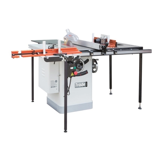
- Page 1 Code 104501 Original Instructions AT254TS Table Saw & Additional Tables AT&M: 06/09/2018 BOOK REF : 007287...
- Page 2 Cert No: HW110LGE-30 EU Declaration of Conformity Axminster Tools & Machinery Ltd This machine complies with the following directives: Axminster Devon EX13 5PH UK axminster.co.uk 2006/42/EC 06/42/EC - Annex I/05.2006 declares that the machinery described:- EN 60204-1:2006+A1+AC EN 1870-19:2013 Type...
-
Page 4: Machine Description
3. Machine Description 3.1 Technical parameters Item HW110LGE-30 HW110LGE-50 260Kg (approx.) weight Product Dimensions length/width/height(mm) 1582x1100x1016 2090x1100x1016 foot print(length/width) 508x508 Electrical: switch magnetic with thermal overload protection type TEFC capacitor start induction horsepower/voltage/phase/amps 3HP-230V-1PH 12.8A Motor speed/cycle 2850 RPM/50HZ power transfer Triple V-belt Drive maximum blade diameter 250mm... - Page 7 3.5 Noise 4. Safety Regulations 3.5.1 Reference standards 4.1 General Safety Instructions measurements noise emission were 1. KNOW YOUR MACHINE. conducted according to the EN ISO 11202 for the Read and understand the owners manual and labels determination of sound pressure level at the affixed to the machine.
- Page 8 in moving parts. Non-slip footwear is recommended. 4.2 Specific Safety Instructions for Wear protective hair covering to contain long hair. Sliding Table Saw Roll up long sleeves above the elbows; 1. ALWAYS USE A GUARD. 12. DON’T OVER REACH. Always use a guard, splitter and anti-kickback Keep proper footing and balance at all times;...
-
Page 13: Install The Switch
is directly under the red line on the pointer window as shown; lightly mark the “0” location on the tube with a pencil, then remove the fence; peel the tape and carefully align the “0” mark on the scale with the pencil mark you made;... -
Page 14: Install The Blade
disengages the bracket and the locking pin engages 5.4.7 Install the blade the hole in the center of the spreader. A. Remove blade guard assembly & table insert. C. give the spreader an upward tug to verify that it is B. -
Page 16: Electrical Connections
electric power to this machine, in order to protect After finishing wiring on the spot, check the following people against electrical shock due to indirect shock items at least: Wiring: Check the wirings of machine. Finish electrical connection according to the Check the direction of motors and change wiring if electrical drawings. -
Page 18: Positive Stops
6.3 Aligning Table T-slot Parallel With 6.4 Adjusting 45 and 90 Degree Blade Positive Stops 1,The table T-slot must be aligned parallel with the The blade tilting mechanism of your saw is equipped blade. Using a combination square (A) as Fig.24, with a positive stop at 45 and 90 degrees. -
Page 22: Maintenance
matching set of V-belts onto the pulleys, lower the 8. Maintenance motor to tension the V-belts, then tighten the hex This table saw requires very little maintenance other nuts. than minor lubrication and cleaning. The following 4. Close the motor access cover. sections detail what will need to be done in order to assure continued operation of your saw. -
Page 23: Trouble Shouting Guide
9. Trouble Shouting Guide PROBLEM SOLUTION SAW WILL NOT START 1. Saw not plugged in. 1. Plug in saw. 2. Fuse blown or circuit breaker tripped. 2. Replace fuse or reset circuit breaker. 3. Cord damaged. 3. Have cord replaced by a certified electrician. OVERLOAD KICKS OUT FREQUENTLY 1. - Page 24 10. Parts List Table Saw Body Breakdown...
- Page 26 Trunnion Assembly Breakdown...
-
Page 27: Trunnion Assembly Parts List
Trunnion Assembly Parts List REF# DERIPTION REF# DERIPTION handwheel lock hex bolt M10x45 handwheel lock washer 10 set screw M5x12 flat washer 10 point 1 arbor nut set screw M5x6 arbor flange point 2 set screw M5x12 cap screw M6*12 arbor lock washer 6 key 5x30... - Page 28 nut M10 2001 knurled knob cap screw M6*25 2002 spring washer 2003 cap screw M8*30 2004 bracket plate gear 2005 set screw M6x12 back bracket 2006 lock washer 6 left bracket 2007 limit coller right bracket 2008 splitter tighten clip square HD bolt 2009 cap screw M6*30...
-
Page 29: Blade Guard Breakdown
Blade Guard Breakdown Blade Guard Parts List REF# DERIPTION REF# DERIPTION splitter phlp HD screw M6-1×25 left guard lock washer 6 right guard lock washer 10 cap screw M10x30 riving knife... -
Page 32: Fence Breakdown
Fence Breakdown Fence Parts List REF# DERIPTION REF# DERIPTION cover hex bolt M10-1.5x45 glide pad lock nut M10-1.5 cam foot fence scale window magnet set screw M12-1.75x15 phlp hd screw M5-0.8x10 fence lock knob lock washer 5 set screw M12-1.75x30 indicator knob special locking nut M12... - Page 33 30″Rail & Extension Table Breakdown 30″Rail & Extension Table Parts List REF# DERIPTION REF# DERIPTION guide tube insert hex bolt 5/16-18x1-1/2 guide tube lock washer 8 scale flat washer 8 front rail rear rail cap screw M6-1x16 hex bolt M8-1.25x40 lock washer 6 nut M8-1.25 flat washer 6...
- Page 34 50″Rail & Extension Table Breakdown 50″Rail & Extension Table Parts List REF# DERIPTION REF# DERIPTION foot tube cover cap screw M6*16 phlp HD screw M8-1.25×40 rear rail lock washer 6 tube flat washer 6 scale hex bolt 5/16-18x1-1/2 front rail lock washer 8 flat washer 8 extension table...
-
Page 35: Switch Breakdown
Switch Breakdown Switch Parts List REF# DERIPTION REF# DERIPTION 701A switch lock washer 5 701D cable flat washer 5 701E cable chain Perforated pin Switch bracket hex bolt M6x12 lock washer 6 strain relief flat washer 6 rivet nut M5x12 Phillips screw M6x12 flat washer 5 phlp HD screw M5-.8×16... -
Page 36: Product Configuration List
1. Foreword This instruction manual only for the table saw equipped with ST1400 & RT100. The content includes: Product configuration and model, space requirements, the installation of switch box and the use of the guide rail. 2. Product configuration list Model Options HW110WS... -
Page 37: Space Requirements
3. Space Requirements Before your setup, you must insure the interspace between the machine and wall at least 800mm. 3.1 Model :HW110S-S , HW110WS-S Fig.1... - Page 38 3.2 Model:HW110WS Fig.2...
- Page 39 4. Change the installation position of switch When install the sliding table, you must change the installation position of the switch, you can install the magnetic switch onto the bottom of the sliding table with three sets hex bolts, as shown in Fig.3 M6-1x 12 hex bolts……..3 6mm lock washers...……3...
- Page 40 Attachment file: WS-30″Short Rail Breakdown WS-30″Short Rail Parts List REF# DERIPTION REF# DERIPTION tube cover hex bolt 5/16-18x1-1/2 602W tube(30") lock washer 8 scale ( 30") flat washer 8 604W 611W front rail ( 30") rear rail(30") cap screw M6*16 hex bolt M8x40 lock washer 6 nut 8...
- Page 41 WS-50″Short Rail Breakdown WS-50″Short Rail Parts List REF# DERIPTION REF# DERIPTION tube cover flat washer 8 scale ( 50") hex bolt M8x40 cap screw M6*16 nut 8 lock washer 6 628WS rear rail(50") flat washer 6 629WS tube(50") 631WS front rail ( 50") hex bolt 5/16-18x1-1/2 lock washer 8...
- Page 44 The Axminster guarantee is available on Craft, Trade, Engineer, Air Tools & CNC Technology Series machines Buy with confidence from Axminster! So sure are we of the quality, we cover all parts and labour free of charge for three years! For more information visit axminster.co.uk/3years...