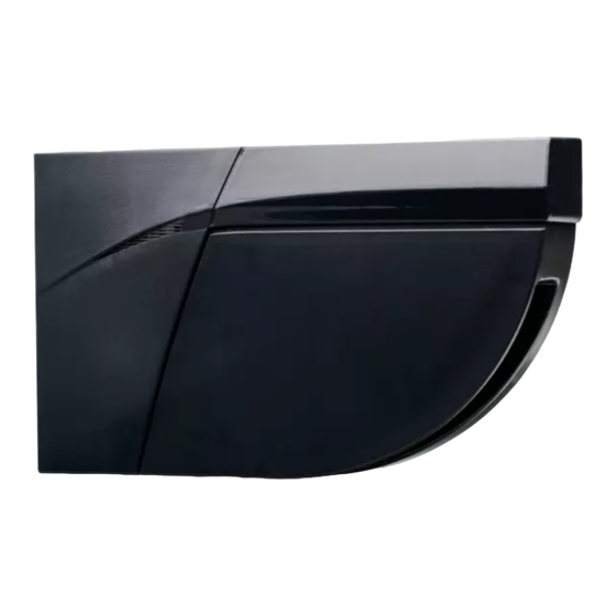
Summary of Contents for BEA LZR-FLATSCAN REV-LZ
- Page 1 ® -FLATSCAN REV-LZ SAFETY SENSOR FOR REVOLVING DOORS User’s Guide for product version 0202 and higher See product label for serial number...
-
Page 2: Installation Tips
INSTALLATION TIPS Remove the laser window Avoid vibrations. Do not cover Avoid moving objects protection before the laser window. and light sources in the teach-in and the the detection field. commissioning of the sensor. Avoid the presence Avoid condensation. Avoid exposure to Keep the sensor permanently of smoke and fog in sudden and extreme... -
Page 3: Led Signals
DESCRIPTION ® The LZR FLATSCAN REV-LZ is a protective sensor for revolving doors based on laser technology. It detect the test body CA (acc. to EN 16005) in the area in front of the door wing. To do so, a module must be installed in the upper corner of each door leaf. - Page 4 MOUNTING ON DOOR Take the base and put it on the door frame. Slide the base off the sensor module. The positioning aids help you to align the base correctly. When mounting the base, make sure the sensor will not hinder the door movement. If the sensor isn’t correctly positioned, it could be crushed during the opening of the door.
- Page 5 Using a wire cutter, remove the positioning aids from Fasten the 3 screws using a Pozidrive screwdriver. the base. The base needs to be fixed firmly! We provide two cabling modes (1a or 1b), please process following steps according to the site condition. HIDE CABLE INSIDE THE SENSOR Ø...
- Page 6 Connect the plug to the white connector. Make sure that all wires are safely tucked within the notch to avoid crushing them with the cover. «click» Close the sensor which will not be connected to the Fasten the lock screw firmly. door controller using a plug.
- Page 7 Pass the power cable through the flexible tube. Make a loop with the wires of the power cable and Connect the plug to the white connector. pass them through the notch as indicated. Use the other part of the cable to block the wires. Take the clamp to fix the flexible tube to the sensor.
- Page 8 DIP-SWITCH 1 Make sure the setting of DIP 1 is correct. TEACH-IN PROCESS Standard Mode 1 2 3 4 Output from R1, red LED flashes when there is a detection. A rectangle shape can be traced in the detection area during the learning (Recommend Mode)...
-
Page 9: Testing And Adjusting
TESTING AND ADJUSTING Check the correct positioning of the If necessary, adjust the tilt angle of the laser curtain by turning the safety fields by placing an object in tilt angle adjustment screw (from 2° to 10°). the detection field. After changing the angle, the sensor position or the environment, always launch a teach-in and test the correct positioning of the detection fields. -
Page 10: Output Configuration
DIP-SWITCH SETTINGS (OPTIONAL) 1 2 3 4 Switch to CRITICAL when external disturbances DIP 2 ENVIRONMENT standard critical are likely to cause unwanted detections (min. obj. size, immunity and uncovered zone are increased). Switch to OFF when there is no background DIP 3 BACKGROUND (glass floor, footbridge...). - Page 11 In order to change these settings by remote control, adjust DIP-switch 2 to ON IMMUNITY FILTER > > > > > > > high Increase to filter out external disturbances. The reaction time increases significantly between value 5 and 9. In order to change these settings by remote control, adjust DIP-switch 2 to ON UNCOVERED ZONE Increase in case of snow, dead leaves, etc.
-
Page 12: How To Use The Remote Control
HOW TO USE THE REMOTE CONTROL After unlocking, the red If the red LED flashes quickly after unlocking, you To end an adjustment session, LED flashes and the sensor need to enter an access code from 1 to 4 digits. always lock the sensor. -
Page 13: Detection Fields
DETECTION FIELDS TWO-WING REVOLVING DOOR THREE-WING REVOLVING DOOR DOOR WING SAFETY UNCOVERED ZONE Typ. object size: 10 cm at 4 m Adjustable by remote control factory value: 10 cm... -
Page 14: Troubleshooting
TROUBLESHOOTING In case of unwanted reactions of the door, verify whether the problem is caused by the sensor, or the door controller. To do so, activate the service mode (no safety) and launch a door cycle. If the door cycle is completed successfully, check the sensor. If not, verify the door controller, the wiring or other sensor. The RED or GREEN LED Bad teach-in Launch a new teach-in. - Page 15 The ORANGE LED is on The sensor encounters a Send the sensor back for a technical check-up. permanently. memory problem. The ORANGE LED flashes DIP-switch setting awaiting Corfirm the DIP-switch setting: long push on the push quickly. confirmation. button. The ORANGE LED flashes The sensor signals an Cut and restore power supply.
-
Page 16: Technical Specifications
/ W asia.beasensors.com +86 10 57761630 +86 10 62628775 info@bea-asiapacific.com BEA hereby declares that the equipment type LZR ® -FLATSCAN REV-LZ is in compliance with European Directives 2006/42/EC (Machinery), 2011/65/EU (RoHS) and 2014/30/EU (EMC). Notified Body for EC inspection: 0044 - TÜV NORD CERT GmbH, Langemarckstr. 20, D-45141 Essen.


