Advertisement
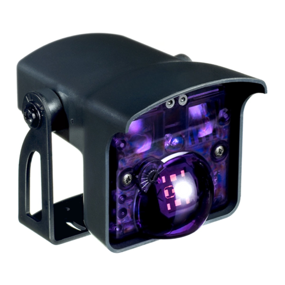
MOTION & PRESENCE SENSOR FOR AUTOMATIC INDUSTRIAL DOORS
38 mm
GREEN
24V
BROWN
GND
WHITE
COM
YELLOW
NO
GREY
NC
PINK
COM
VIOLET
NC
BLACK
NO
45°
30°
15°
-
+
F1
F2
Select parameter
RED
0
POWER
SUPPLY
Only necessary if factory values do not match.
2
1
3
4
5
6
...
7
8
9
0
Set value
RED
RED
CONDOR
QUICK GUIDE
OFF
See user's guide on the
next pages for more
detailed information.
p.3
p.3
p.4
0
p.4
p.5
p.6
Advertisement
Table of Contents

Summary of Contents for BEA CONDOR
- Page 1 CONDOR QUICK GUIDE MOTION & PRESENCE SENSOR FOR AUTOMATIC INDUSTRIAL DOORS 38 mm GREEN POWER BROWN SUPPLY WHITE YELLOW GREY PINK VIOLET BLACK 45° 30° 15° Only necessary if factory values do not match. Select parameter Set value See user’s guide on the next pages for more detailed information.
-
Page 2: Installation Tips
CONDOR USER’S GUIDE MOTION & PRESENCE SENSOR FOR AUTOMATIC INDUSTRIAL DOORS DESCRIPTION Push buttons Fixing bracket Radar tilt angle adjustment screw Infrared detection sensor Radar detection sensor LED-SIGNAL AND SYMBOLS GREEN LED RED LED RED-GREEN LED SETUP RADAR flashes quickly... - Page 3 STEP 1 MOUNTING Minimum distances in mm required to fully adjust the sensor: WALL MOUNTING CEILING MOUNTING 38 mm STEP 2 WIRING GREEN POWER BROWN SUPPLY YELLOW GREY WHITE NO POWER RADAR YELLOW OUTPUT NO DETECTION GREY MOTION SIGNAL DETECTION VIOLET BLACK PINK...
-
Page 4: Sensor Angle
ANGLE ADJUSTMENTS STEP 3 SENSOR ANGLE RECOMMENDED NOT RECOMMENDED 45° Sensor angle: 20° Sensor angle: 30° Sensor angle: 45° 30° 15° Mounting height: 5m Mounting height: 5m Mounting height: 5m Guideline values for a 50 x 50cm² 1.8 x 1.8m² testbody. -
Page 5: Remote Control
REMOTE CONTROL STEP 5 SETTINGS Only necessary if factory values do not match. Minimum size of target unlock lock value check setup Output redirection The position of the target in the Radar output IR output field is random. motion presence presence airlock mode IR-detection field... -
Page 6: How To Use
REMOTE CONTROL STEP 6 SETUP Launch a setup to make a reference picture. Step out of the detection field and do not RED-GREEN RED-GREEN leave any tools inside the detection field during the setup procedure. The installation is completed! HOW TO USE? How to adjust one or more parameters? Select parameter Set value... -
Page 7: Troubleshooting
TROUBLESHOOTING SYMPTOMS POSSIBLE CAUSES CORRECTIVE ACTION Launch a setup. The red LED lights The sensor detects a presence. Wait as long as the time set in the “maximum duration of presence detection” setting. The red LED is Cut and restore the power supply The sensor fails the IR setup. -
Page 8: Technical Specifications
( ) or mail ( www.bea.be) +32 4 361 65 65 info@bea.be) BEA SA - LIEGE Science Park - Allée des Noisetiers 5 - B-4031 Angleur - T +32 4 3616565 - F +32 4 3612858 - info@bea.be - www.bea.be...


