Table of Contents
Advertisement
Available languages
Available languages
Quick Start
Thank you for purchasing the MSI
970A GAMING PRO CARBON
®
motherboard. This Quick Start section provides demonstration
diagrams about how to install your computer. Some of the
installations also provide video demonstrations. Please link to the
URL to watch it with the web browser on your phone or tablet. You
may have even link to the URL by scanning the QR code.
Kurzanleitung
Danke, dass Sie das MSI
970A GAMING PRO CARBON
Motherboard
®
gewählt haben. Dieser Abschnitt der Kurzanleitung bietet eine Demo
zur Installation Ihres Computers. Manche Installationen bieten
auch die Videodemonstrationen. Klicken Sie auf die URL, um diese
Videoanleitung mit Ihrem Browser auf Ihrem Handy oder Table
anzusehen. Oder scannen Sie auch den QR Code mit Ihrem Handy,
um die URL zu öffnen.
Présentation rapide
Merci d' avoir choisi la carte mère MSI
970A GAMING PRO
CARBON.
®
Ce manuel fournit une rapide présentation avec des illustrations
explicatives qui vous aideront à assembler votre ordinateur. Des
tutoriels vidéo sont disponibles pour certaines étapes. Cliquez sur
le lien fourni pour regarder la vidéo sur votre téléphone ou votre
tablette. Vous pouvez également accéder au lien en scannant le QR
code qui lui est associé.
Быстрый старт
Благодарим вас за покупку материнской платы MSI
®
CARBON. В этом разделе представлена
970A GAMING PRO
информация, которая поможет вам при сборке комьютера.
Для некоторых этапов сборки имеются видеоинструкции.
Для просмотра видео, необходимо открыть
соответствующую ссылку в веб-браузере на вашем телефоне
или планшете. Вы также можете выполнить переход по
ссылке, путем сканирования QR-кода.
I
Quick Start
Advertisement
Chapters
Table of Contents

Related Manuals for MSI 970A GAMING PRO CARBON


Summary of Contents for MSI 970A GAMING PRO CARBON
- Page 1 Videoanleitung mit Ihrem Browser auf Ihrem Handy oder Table anzusehen. Oder scannen Sie auch den QR Code mit Ihrem Handy, um die URL zu öffnen. Présentation rapide Merci d’ avoir choisi la carte mère MSI 970A GAMING PRO CARBON. ®...
- Page 2 Installing a Processor/ Installation des Prozessors/ Installer un processeur/ Установка процессора http://youtu.be/zGR-s3xgPik Quick Start...
- Page 3 Installing DDR3 memory/ Installation des DDR3-Speichers/ Installer une mémoire DDR3/ Установка памяти DDR3 http://youtu.be/76yLtJaKlCQ Quick Start...
- Page 4 Connecting the Front Panel Header/ Anschließen der Frontpanel-Stiftleiste/ Connecter un connecteur du panneau avant/ Подключение разъемов передней панели http://youtu.be/DPELIdVNZUI HDD LED + Power LED + HDD LED - Power LED - Reset Switch Power Switch Reset Switch Power Switch JFP1 Reserved No Pin JFP1...
- Page 5 Installing the Motherboard/ Installation des Motherboards/ Installer la carte mère/ Установка материнской платы Quick Start...
- Page 6 Installing SATA Drives/ Installation der SATA-Laufwerke/ Installer le disque dur SATA/ Установка дисков SATA http://youtu.be/RZsMpqxythc Quick Start...
- Page 7 Installing a Graphics Card/ Einbau der Grafikkarte/ Installer une carte graphique/ Установка дискретной видеокарты http://youtu.be/mG0GZpr9w_A Quick Start...
- Page 8 Connecting Peripheral Devices/ Peripheriegeräte/ Connecter un périphérique anschliessen/ Подключение периферийных устройств VIII Quick Start...
- Page 9 Connecting the Power Connectors/ Stromanschlüsse anschliessen/ Connecter les câbles du module d’ alimentation/ Подключение разъемов питания http://youtu.be/gkDYyR_83I4 ATX_PWR1 CPU_PWR1 Quick Start...
- Page 10 Power On/ Einschalten/ Mettre sous-tension/ Включение питания Quick Start...
-
Page 11: Table Of Contents
Contents Safety Information ....................2 Specifications ......................3 Rear I/O Panel ....................... 8 LAN Port LED Status Table..................8 Audio Ports Configuration ..................8 Overview of Components ..................10 CPU Socket ......................11 DIMM Slots ......................12 PCI_E1~5, PCI1: PCIe/ PCI Expansion Slots ............13 M2_1: M.2 Slot ...................... -
Page 12: Safety Information
Safety Information The components included in this package are prone to damage from electrostatic discharge (ESD). Please adhere to the following instructions to ensure successful computer assembly. Ensure that all components are securely connected. Loose connections may cause the computer to not recognize a component or fail to start. Hold the motherboard by the edges to avoid touching sensitive components. -
Page 13: Specifications
Specifications Supports AMD / Phenom / Athlon II/ Sempron ® ™ ™ ™ ™ processors for Socket AM3/ AM3+ Chipset 970 & SB950 Chipset ® 4x DDR3 memory slots, support up to 32GB Memory Supports DDR3 1066/ 1333/ 1600/ 1866/ 2133(OC) MHz ƒ... - Page 14 Continued from previous page 1x PS/2 keyboard/ mouse combo port 8x USB 2.0 ports 1x USB 3.1 Gen2 Type-A port Back Panel 1x USB 3.1 Gen2 Type-C port Connectors 1x LAN (RJ45) port 1x optical S/PDIF OUT connector 6x audio jacks 1x 24-pin ATX main power connector 1x 8-pin ATX 12V power connector 6x SATA 6Gb/s connectors...
- Page 15 Continued from previous page Drivers COMMAND CENTER LIVE UPDATE 6 FAST BOOT SUPER CHARGER GAMING APP USB SPEED UP Software GAMING LAN MANAGER Nahimic 2 Open Broadcaster Software Norton™ Internet Security Solution Google Chrome™ ,Google Toolbar, Google Drive SteelSeries Engine 3 DRAGON EYE Continued on next page Specifications...
- Page 16 GAMING CERTIFIED WTFast GPN 2-Month Premium License* ƒ Multi-Server Network Optimization ƒ Advanced Lag Spike & Disconnect Reduction ƒ * This offer is valid for a limited period only. For more information please visit www.msi.com Continued on next page Specifications...
- Page 17 MILITARY CLASS 4 Military Class Component ƒ Military Class Stability and Reliability ƒ ESD Protection ˜ EMI Protection ˜ Humidity Protection ˜ MSI Exclusive Circuit Protection ˜ Features High Temperature Protection ˜ VGA Armor Slot ˜ COMMAND CENTER System Monitor ƒ...
-
Page 18: Rear I/O Panel
Rear I/O Panel Audio Ports PS/2 USB 3.1 Optical S/PDIF-Out Gen2 USB 3.1 Gen2 Type-C USB 2.0 LAN Port LED Status Table Link/ Activity LED Speed LED Status Description Status Description No link 10 Mbps connection Yellow Linked Green 100 Mbps connection Blinking Data activity Orange... - Page 19 Audio jacks to headphone and microphone diagram Audio jacks to stereo speakers diagram AUDIO INPUT Audio jacks to 7.1-channel speakers diagram AUDIO INPUT Rear Front Side Center/ Subwoofer Rear I/O Panel...
-
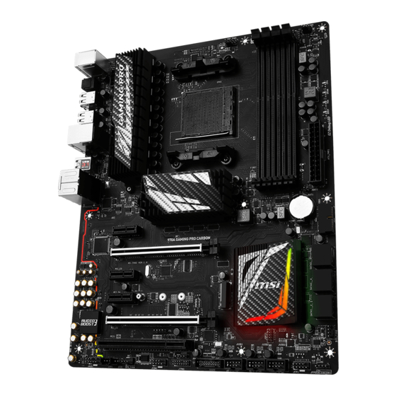
Page 20: Overview Of Components
Overview of Components DIMMB2 CPU_FAN1 DIMMB1 CPU Socket CPU_PWR1 DIMMA2 SYS_FAN3 SYS_FAN1 DIMMA1 EZ Debug LED ATX_PWR1 JBAT1 PCI_E1 JUSB5 PCI_E2 SATA5_6 PCI_E3 SATA3_4 PCI_E4 SATA1_2 PCI_E5 SYS_FAN2 PCI1 M2_1 JAUD1 JFP2 JSP1 SYS_FAN4 JFP1 JCOM1 JUSB3 JCI1 JTPM1 JUSB2 JLED1 JUSB1 JUSB4... -
Page 21: Cpu Socket
Always unplug the power cord from the power outlet before installing or removing the CPU. Please retain the CPU protective cap after installing the processor. MSI will deal with Return Merchandise Authorization (RMA) requests if only the motherboard comes with the protective cap on the CPU socket. -
Page 22: Dimm Slots
DIMM Slots DIMMA1 DIMMB1 Channel A Channel B DIMMA2 DIMMB2 Memory module installation recommendation DIMMB1 DIMMB2 DIMMB1 DIMMA1 DIMMA1 DIMMA2 DIMMA1 Important Always insert memory modules in the DIMMA1 slot first. Due to chipset resource usage, the available capacity of memory will be a little less than the amount of installed. -
Page 23: Pci_E1~5, Pci1: Pcie/ Pci Expansion Slots
If you install a large and heavy graphics card, you need to use a tool such as MSI Gaming Series Graphics Card Bolster to support its weight and to prevent deformation of the slot. Overview of Components... -
Page 24: M2_1: M.2 Slot
M2_1: M.2 Slot Important Intel RST only supports PCIe M.2 SSD with UEFI ROM, ® does not support Legacy ROM. Video Demonstration Watch the video to learn how to Install M.2 module. http://youtu.be/JCTFABytrYA Installing M.2 module Remove the screw from the base screw. -
Page 25: Sata1~6: Sata 6Gb/S Connectors
SATA1~6: SATA 6Gb/s Connectors These connectors are SATA 6Gb/s interface ports. Each connector can connect to one SATA device. SATA6 SATA5 SATA4 SATA3 SATA2 SATA1 Important Please do not fold the SATA cable at a 90-degree angle. Data loss may result during transmission otherwise. -
Page 26: Cpu_Pwr1, Atx_Pwr1: Power Connectors
CPU_PWR1, ATX_PWR1: Power Connectors These connectors allow you to connect an ATX power supply. CPU_PWR1 Ground +12V Ground +12V Ground +12V Ground +12V +3.3V +3.3V +3.3V -12V Ground Ground PS-ON# Ground Ground Ground ATX_ Ground Ground PWR1 PWR OK 5VSB +12V +12V +3.3V... -
Page 27: Jusb4~5: Usb 3.1 Gen1 Connectors
JUSB4~5: USB 3.1 Gen1 Connectors These connectors allow you to connect USB 3.1 Gen1 ports on the front panel. JUSB5 JUSB4 Power USB2.0+ USB3_RX_DN USB2.0- USB3_RX_DP Ground Ground USB3_TX_C_DP USB3_TX_C_DN USB3_TX_C_DN USB3_TX_C_DP Ground Ground USB3_RX_DP USB2.0- USB3_RX_DN USB2.0+ Power No Pin Important Note that the Power and Ground pins must be connected correctly to avoid possible damage. -
Page 28: Jusb1~3: Usb 2.0 Connectors
JUSB1~3: USB 2.0 Connectors These connectors allow you to connect USB 2.0 ports on the front panel. USB0- USB1- USB0+ USB1+ Ground Ground No Pin Important Note that the VCC and Ground pins must be connected correctly to avoid possible damage. -
Page 29: Cpu_Fan1, Sys_Fan1~4: Fan Connectors
CPU_FAN1, SYS_FAN1~4: Fan Connectors Fan connectors can be classified as PWM (Pulse Width Modulation) Mode and Voltage Mode. PWM Mode fan connectors provide constant 12V output and adjust fan speed with speed control signal. Voltage Mode fan connectors control fan speed by changing voltage. -
Page 30: Jaud1: Front Audio Connector
JAUD1: Front Audio Connector This connector allows you to connect audio jacks on the front panel. MIC L Ground MIC R Head Phone R MIC Detection SENSE_SEND No Pin Head Phone L Head Phone Detection JCI1: Chassis Intrusion Connector This connector allows you to connect the chassis intrusion switch cable. Normal Trigger the chassis intrusion event... -
Page 31: Jled1: Rgb Led Connector
JLED1: RGB LED connector This connector allows you to connect the RGB LED strip. +12V Important This connector supports 5050 RGB multi-color LED strips (12V/G/R/B) within 2 meters. Always turn off the power supply and unplug the power cord from the power outlet before installing or removing the RGB LED strip. -
Page 32: Jbat1: Clear Cmos (Reset Bios) Jumper
JBAT1: Clear CMOS (Reset BIOS) Jumper There is CMOS memory onboard that is external powered from a battery located on the motherboard to save system configuration data. If you want to clear the system configuration, set the jumpers to clear the CMOS memory. Keep Data Clear CMOS/ Reset BIOS... -
Page 33: Bios Setup
Press Delete key, when the Press DEL key to enter Setup Menu, F11 to enter Boot Menu message appears on the screen during the boot process. Use MSI FAST BOOT application. Click on GO2BIOS button and choose OK. The system will reboot and enter BIOS setup directly. -
Page 34: Resetting Bios
Updating BIOS Updating BIOS with M-FLASH Before updating: Please download the latest BIOS file that matches your motherboard model from MSI website. And then save the BIOS file into the USB flash drive. Updating BIOS: Press Del key to enter the BIOS Setup during POST. -
Page 35: Overview
Virtual OC Genie Button - enables or disables the OC Genie function by clicking on this button. When enabled, this button will be light. Enabling OC Genie function can automatically overclock with MSI optimized overclocking profile. Important We recommend that you do not to make any modification in OC menu mode and do not to load defaults after enabling the OC Genie function. -
Page 36: Oc Menu
OC Menu This menu is for advanced users who want to overclock the motherboard. Important Overclocking your PC manually is only recommended for advanced users. Overclocking is not guaranteed, and if done improperly, it could void your warranty or severely damage your hardware. If you are unfamiliar with overclocking, we advise you to use OC Genie function for easy overclocking. - Page 37 CPU Core Control [Auto] This item allows you to select the number of active processor cores. When set to Auto, the CPU will operate under the default number of cores. DRAM Frequency [Auto] Sets the DRAM frequency. Please note the overclocking behavior is not guaranteed. Adjusted DRAM Frequency Shows the adjusted DRAM frequency.
- Page 38 Enter OC and set Unlock CPU Core to Enabled. Set Adjust CPU-NB Ratio and HT Link Speed to [x8]. Save changes and exit the BIOS setup. System restart. Clear CMOS data. Fail Success You will see the X4 (quad core) or X2 (dual core for The CPU does not support CPU core unlocking, please leave the default Sempron series only) during POST.
- Page 39 CPU Specifications Press Enter to enter the sub-menu. This sub-menu displays the information of installed CPU. You can also access this information menu at any time by pressing F4. Read only. fCPU Technology Support Press Enter to enter the sub-menu. The sub-menu shows the key features of installed CPU.
-
Page 40: Software Description
7/ 8.1/ 10. ® Installing Drivers Start up your computer in Windows 7/ 8.1/ 10. ® Insert MSI Driver Disc into your optical drive. ® The installer will automatically appear and it will find and list all necessary drivers. Click Install button. - Page 41 Inhalt Sicherheitshinweis ....................2 Spezifikationen ...................... 3 Rückseite E/A ......................8 LAN Port LED Zustandstabelle ................8 Konfiguration der Audioanschlüsse ............... 8 Übersicht der Komponenten ................10 CPU Socket ......................11 DIMM-Steckplätze ....................12 PCI_E1~5, PCI1: PCIe/ PCI Erweiterungssteckplätze .......... 13 M2_1: M.2 Steckplatz ...................
-
Page 42: Sicherheitshinweis
Sicherheitshinweis Die im Paket enthaltene Komponenten sind der Beschädigung durch elektrostatischen Entladung (ESD). Beachten Sie bitte die folgenden Hinweise, um die erfolgreichen Computermontage sicherzustellen. Stellen Sie sicher, dass alle Komponenten fest angeschlossen sind. Lockere Steckverbindungen können Probleme verursachen, zum Beispiel: Der Computer erkennt eine Komponente nicht oder startet nicht. -
Page 43: Spezifikationen
Spezifikationen Unterstützt AMD / Phenom / Athlon II/ Sempron ® ™ ™ ™ ™ Prozessoren für AM3/ AM3+ Sockel Chipsatz 970 & SB950 Chipsatz ® 4x DDR3 Speicherplätze, aufrüstbar bis 32GB Speicher Unterstützt DDR3 1066/ 1333/ 1600/ 1866/ 2133(OC) MHz ƒ... - Page 44 Fortsetzung der vorherigen Seite Realtek ALC1150 Codec ® Audio 7.1-Kanal-HD-Audio Unterstützt S/PDIF-Ausgang Intel I211-AT Gigabit LAN Controller x1 PS/2 Tastatur/ Maus-Combo-Anschluss x1 USB 2.0 Anschlüsse x8 USB 3.1 Gen2 Typ-A Anschluss x1 Hintere Ein-/ und USB 3.1 Gen2 Typ-C Anschluss x1 Ausgänge LAN (RJ45) Anschluss x1 Optischer S/PDIF-Ausgang x1...
- Page 45 Fortsetzung der vorherigen Seite Treiber COMMAND CENTER LIVE UPDATE 6 FAST BOOT SUPER CHARGER GAMING APP USB SPEED UP Software GAMING LAN MANAGER Nahimic 2 Open Broadcaster Software Norton™ Internet Security Solution Google Chrome , Google Toolbar, Google Drive ™ SteelSeries Engine 3 DRAGON EYE Fortsetzung auf der nächsten Seite...
- Page 46 ƒ GAMING CERTIFIED WTFast GPN 2-Monate Premiumlizenz* ƒ Multiserver-Netzwerkoptimierung ƒ Verbesserte Reduktion von Lag Spikes ƒ &Verbindungseinbrüchen * Dieses Angebot steht nur für begrenzte Zeit zur Verfügung , weitere Informationen finden Sie unter www.msi.com Fortsetzung auf der nächsten Seite Spezifikationen...
- Page 47 Hardware Monitor ƒ MILITARY CLASS 4 Military Class Komponenten ƒ Military Class Stabilität und Zuverlässigkeit ƒ ESD-Schutz ˜ EMI-Schutz ˜ Luftfeuchtigkeit Schutz ˜ MSI Exklusive Schaltkreisschutz ˜ Merkmale Übertemperaturschutz ˜ VGA Armor Steckplatz ˜ COMMAND CENTER System-Monitor ƒ Smart-Lüftersteuerung ƒ...
-
Page 48: Rückseite E/A
Rückseite E/A Audioanschlüsse PS/2 Optischer S/PDIF- USB 3.1 Ausgang Gen2 USB 3.1 Gen2 Typ-C USB 2.0 LAN Port LED Zustandstabelle Verbindung/ Aktivität LED Geschwindigkeit LED Zustand Bezeichnung Zustand Bezeichnung Keine Verbindung 10 Mbps-Verbindung Gelb Verbindung Grün 100 Mbps-Verbindung Blinkt Datenaktivität Orange 1 Gbps-Verbindung Konfiguration der Audioanschlüsse... - Page 49 Audiobuchsen für den Anschluss von einem Kopfhörer und Mikrofon Audiobuchsen für Stereo-Lautsprecher AUDIO INPUT Audiobuchsen für 7.1 Kanal Anlage AUDIO INPUT Rear Front Side Center/ Subwoofer Rückseite E/A...
-
Page 50: Übersicht Der Komponenten
Übersicht der Komponenten DIMMB2 CPU_FAN1 DIMMB1 CPU Sockel CPU_PWR1 DIMMA2 SYS_FAN3 SYS_FAN1 DIMMA1 EZ Debug LED ATX_PWR1 JBAT1 PCI_E1 JUSB5 PCI_E2 SATA5_6 PCI_E3 SATA3_4 PCI_E4 SATA1_2 PCI_E5 SYS_FAN2 PCI1 M2_1 JAUD1 JFP2 JSP1 SYS_FAN4 JFP1 JCOM1 JCI1 JUSB3 JTPM1 JUSB2 JLED1 JUSB1 JUSB4... -
Page 51: Cpu Socket
Sie jedoch bitte sicher, dass die betroffenen Komponenten mit den abweichenden Einstellungen während des Übertaktens zurecht kommen. Von jedem Versuch des Betriebes außerhalb der Produktspezifikationen kann nur abgeraten werden. MSI übernehmt keinerlei Garantie für die Schäden und Risiken, die aus einem unzulässigem Betrieb oder einem Betrieb außerhalb der Produktspezifikation resultieren. -
Page 52: Dimm-Steckplätze
DIMM-Steckplätze DIMMA1 DIMMB1 Kanal A Kanal B DIMMA2 DIMMB2 Speichermodul-Installationsempfehlung DIMMB1 DIMMB2 DIMMB1 DIMMA1 DIMMA1 DIMMA2 DIMMA1 Wichtig Um einen sicheren Systemstart zu gewährleisten, bestücken Sie immer DIMMA1 zuerst. Aufgrund der Chipsatzressourcennutzung wird die verfügbare Kapazität des Speichers kleiner sein als die Größe der installierten Speicherkapazität. Bitte beachten Sie, dass die maximale Kapazität eines 32-Bit-Windows- Betriebssystem bei 4GB oder weniger liegt. -
Page 53: Pci_E1~5, Pci1: Pcie/ Pci Erweiterungssteckplätze
PCI_E1~5, PCI1: PCIe/ PCI Erweiterungssteckplätze PCI_E1: PCIe 2.0 x1-Steckplatz PCI_E2: PCIe 2.0 x16-Steckplatz PCI_E3: PCIe 2.0 x1-Steckplatz PCI_E4: PCIe 2.0 x1-Steckplatz PCI_E5: PCIe 2.0 x8-Steckplatz PCI1: PCI-Steckplatz Mehrere Grafikkarten Einbauempfehlung Wichtig Für die Installation einer einzelnen PCIe x16 Erweiterungskarte mit optimaler Leistung, empfehlen wir den PCI_E2 Steckplatz zu verwenden. -
Page 54: M2_1: M.2 Steckplatz
M2_1: M.2 Steckplatz Wichtig Intel RST unterstützt nur PCIe M.2 SSD mit UEFI ROM, ® Legacy-ROM wird NICHT unterstützt. Video-Demonstration Eine anschauliche Darstellung zur Installation eines M.2 Moduls finden Sie im Video. http://youtu.be/JCTFABytrYA Installation eines M.2 Moduls Entfernen Sie die Schraube aus dem Schraubsockel. -
Page 55: Sata1~6: Sata 6Gb/S Anschlüsse
SATA1~6: SATA 6Gb/s Anschlüsse Dieser Anschluss basiert auf der Hochgeschwindigkeitsschnittstelle SATA 6Gb/s. Pro Anschluss kann ein SATA Gerät angeschlossen werden. SATA6 SATA5 SATA4 SATA3 SATA2 SATA1 Wichtig Knicken Sie das SATA-Kabel nicht in einem 90° Winkel. Datenverlust könnte die Folge sein. SATA-Kabel haben identische Stecker an beiden Enden. -
Page 56: Cpu_Pwr1, Atx_Pwr1: Stromanschlüsse
CPU_PWR1, ATX_PWR1: Stromanschlüsse Mit diesen Anschlüssen verbinden Sie die ATX Stromstecker. CPU_PWR1 Ground +12V Ground +12V Ground +12V Ground +12V +3.3V +3.3V +3.3V -12V Ground Ground PS-ON# Ground Ground Ground ATX_ PWR1 Ground Ground PWR OK 5VSB +12V +12V +3.3V Ground Wichtig Stellen Sie sicher, dass alle Anschlüsse mit den richtigen Anschlüssen des Netzteils... -
Page 57: Jfp1, Jfp2: Frontpanel-Anschlüsse
JUSB4~5: USB 3.1 Gen1 Anschlüsse Mit diesen Anschlüssen können Sie die USB 3.1 Gen1 Anschlüsse auf dem Frontpanel verbinden. JUSB5 JUSB4 Power USB2.0+ USB3_RX_DN USB2.0- USB3_RX_DP Ground Ground USB3_TX_C_DP USB3_TX_C_DN USB3_TX_C_DN USB3_TX_C_DP Ground Ground USB3_RX_DP USB2.0- USB3_RX_DN USB2.0+ Power No Pin Wichtig Bitte beachten Sie, dass Sie die mit „Stromführende Leitung “... -
Page 58: Jusb1~3: Usb 2.0 Anschlüsse
Bitte beachten Sie, dass Sie die mit VCC (Stromführende Leitung) und Ground (Erdleitung) bezeichneten Pins korrekt verbinden müssen, ansonsten kann es zu Schäden kommen. Um das iPad, iPhone und den iPod über USB-Anschlüsse aufzuladen, installieren Sie bitte die MSI SUPER CHARGER Software. ® JTPM1: TPM Anschluss Dieser Anschluss wird für das TPM Modul (Trusted Platform Module) verwendet. -
Page 59: Cpu_Fan1, Sys_Fan1~4: Stromanschlüsse Für Lüfter
CPU_FAN1, SYS_FAN1~4: Stromanschlüsse für Lüfter Diese Anschlüsse können im PWM (Pulse Width Modulation) Modus oder Spannungsmodus betrieben werden. Im PWM-Modus bieten die Lüfteranschlüsse konstante 12V Spannung und regeln die Lüftergeschwindigkeit per Drehzahlsteuersignal. Im Spannungsmodus bestimmen die Lüfteranschlüsse die Lüftergeschwindigkeit durch Spannungsänderungen. Wenn Sie einen 3-Pin (Non- PWM) Lüfter an einen PWM-Modus Lüfteranschluss anschließen, läuft der Lüfter mit höchster Drehzahl und kann unangenehm laut werden. -
Page 60: Jaud1: Audioanschluss Des Frontpanels
JAUD1: Audioanschluss des Frontpanels Dieser Anschluss ermöglicht den Anschluss von Audiobuchsen eines Frontpanels. MIC L Ground MIC R Head Phone R MIC Detection SENSE_SEND No Pin Head Phone L Head Phone Detection JCI1: Gehäusekontaktanschluss Dieser Anschluss wird mit einem Kontaktschalter verbunden. Normal Löse den Gehäuseeingriff aus... -
Page 61: Jled1: Rgb-Led-Anschluss
JLED1: RGB-LED-Anschluss Mit diesem Anschluss können Sie den RGB-LED-Streifen anschließen. +12V Wichtig Dieser Anschluss unterstützt die 5050 RGB Mehr-Farb-LED-Streifen (12V/G/R/B) bis maximal 2Meter. Schalten Sie die Stromversorgung aus und ziehen Sie das Netzkabel ab, bevor Sie die RGB-LED-Streifen ein- und ausbauen. Sie können den LED Effekt der GAMING APP steuern, um das LED-Licht anzupassen und zu kalibrieren. -
Page 62: Jbat1: Steckbrücke Zur Cmos-Löschung (Reset Des Bios)
JBAT1: Steckbrücke zur CMOS-Löschung (Reset des BIOS) Der Onboard CMOS Speicher (RAM) wird durch eine externe Spannungsversorgung durch eine Batterie auf dem Motherboard versorgt, um die Daten der Systemkonfiguration zu speichern. Wenn Sie die Systemkonfiguration löschen wollen, müssen Sie die Steckbrücke für kurze Zeit umsetzen. Daten CMOS-Daten beibehalten... -
Page 63: Bios-Setup
Während des BOOT-Vorgangs drücken Sie die Taste Delete, wenn die Meldung Press DEL key to enter Setup Menu, F11 to enter Boot Menu erscheint. Verwenden Sie die MSI FAST BOOT Anwendung. Klicken Sie die GO2BIOS-Taste und drücken OK. Das System startet neu und geht direkt ins BIOS. -
Page 64: Reset Des Bios
Aktualisierung des BIOS mit dem M-FLASH-Programm Vorbereitung: Laden Sie bitte die neueste BIOS Version, die dem Motherboard-Modell entspricht, von der offiziellen MSI Website herunter und speichern Sie die BIOS-Datei auf USB-Flash- Laufwerk. BIOS-Aktualisierungsschritte: Drücken Sie während des POST-Vorgangs die Taste (Entf), um das BIOS zu öffnen. -
Page 65: Überbilck
Virtual OC Genie Taste - Aktivieren oder deaktivieren Sie die OC Genie Funktion durch einen Klick auf diese Taste. Wenn aktiviert, leuchtet diese Taste auf. Aktivieren Sie die OC Genie-Funktion mit einem von MSI optimierten Übertaktungsprofil automatisch zu übertakten. Wichtig Es wird empfohlen, keine Änderung im OC-Menü... -
Page 66: Oc-Menü
OC-Menü In diesem Menü können Benutzer das BIOS anpassen und das Mainboard übertakten. Bitte führen Sie nur Änderungen durch, wenn Sie sich über das Ergebnis im Klaren sind. Sie sollten Erfahrung beim Übertakten haben, da Sie sonst das Motherboard oder Komponenten des Systems beschädigen können. Wichtig Die Übertaktung ist nur für fortgeschrittene Benutzer zu empfehlen. - Page 67 CPU Smart Protection [Enabled] CPU Smart Protection ist ein Mechanismen der CPU-Überhitzungsüberwachung. Es wird automatisch reduziert die Taktfrequenz, wenn die CPU Temperatur zu heiß wird. CPU Core Control [Auto] Gesteuert werden dei Anzahl der CPU-Kerne. Mit der Einstellung Auto, wird das CPU unter die standardmäßig zulässigen Korne führen.
- Page 68 Geben Sie OC und setzen Sie Unlock CPU Core auf Enabled. Setzen Sie „Adjust CPU-NB Ratio “ und „HT Link Speed “ auf [x8]. Speichern Sie die Änderungen und verlassen Sie das BIOS-Setup. System neustarten. Löschen Sie das CMOS Daten. Fehler Erfolg Sehen Sie die „X4 “...
- Page 69 CPU Specifications Drücken Sie die Eingabetaste <Enter>, um das Untermenü aufzurufen. Das Untermenü zeigt die Informationen der installierten CPU an. Zu diesen Informationen gelangen Sie, indem Sie die Taste F4 drücken. Nur Anzeige. fCPU Technology Support Drücken Sie die Eingabetaste <Enter>, um das Untermenü aufzurufen. Das Untermenü...
-
Page 70: Softwarebeschreibung
Installation von Treibern Starten Sie Ihren Computer mit Windows 7/ 8.1/ 10. ® Legen Sie die MSI Treiber Disk in das optisches Laufwerk. ® Der Installer wird automatisch erscheint und findet und finden Sie die benötigten Treiber in die Liste. - Page 71 Table des matières Informations de sécurité ..................2 Spécifications ......................3 Panneau arrière Entrée/ Sortie ................8 Tableau explicatif de l’ état de la LED du port LAN ..........8 Configuration des ports audio ................8 Vue d’ ensemble des composants ............... 10 Socket processeur ....................
-
Page 72: Informations De Sécurité
Informations de sécurité Les composants dans l’ emballage peuvent être endommagés par des décharges électrostatiques (ESD). Pour vous assurer de correctement monter votre ordinateur, veuillez vous référer aux instructions ci-dessous. Assurez-vous de bien connecter tous les composants. En cas de mauvaise connexion, il se peut que l’... -
Page 73: Spécifications
Spécifications Support des processeurs AMD / Phenom / Athlon ® ™ ™ ™ Sempron pour socket AM3/ AM3+ ™ Chipset Chipset AMD 970 et SB950 ® 4 x slots pour mémoire DDR3, support jusqu’ à 32 Go Mémoire Support DDR3 1066/ 1333/ 1600/ 1866/ 2133(OC) MHz ƒ... - Page 74 Suite du tableau de la page précédente 1 x contrôleur Intel I211-AT Gigabit LAN 1 x port clavier/ souris PS/2 8 x ports USB 2.0 1 x port USB 3.1 Gen2 Type-A Connecteurs sur le 1 x port USB 3.1 Gen2 Type-C panneau arrière 1 x port LAN (RJ45) 1 x connecteur Sortie S/PDIF optique...
- Page 75 Suite du tableau de la page précédente Pilotes COMMAND CENTER LIVE UPDATE 6 FAST BOOT SUPER CHARGER GAMING APP USB SPEED UP Logiciel GAMING LAN MANAGER Nahimic 2 Open Broadcaster Software Norton™ Internet Security Solution Google Chrome™, Google Toolbar et Google Drive SteelSeries Engine 3 DRAGON EYE Suite du tableau sur la page suivante...
- Page 76 Amélioration du réseau multiserveur ƒ Réduction du lag et des risques de déconnexion ƒ * Cette fonctionnalité dépend d’ une offre limitée dans le temps. Veuillez vous référer au site fr.msi.com pour plus d’ informations. Suite du tableau sur la page suivante Spécifications...
- Page 77 Suite du tableau de la page précédente CLICK BIOS 5 Possibilité d’ alterner entre les modes Simplifié et ƒ Avancé (EZ et Advanced) Board Explorer (Tableau des connecteurs) ƒ Hardware Monitor (Moniteur système) ƒ MILITARY CLASS 4 Composants électroniques Military Class ƒ...
-
Page 78: Panneau Arrière Entrée/ Sortie
Panneau arrière Entrée/ Sortie Ports Audio PS/2 USB 3.1 Sortie S/PDIF optique Gen2 USB 3.1 Gen2 Type-C USB 2.0 Tableau explicatif de l’ état de la LED du port LAN LED indiquant la connexion LED indiquant la vitesse et l’ activité Etat Description Etat... - Page 79 Ilustration de l’ utilisation des ports audio dédiés au casque et au microphone Ilustration de l’ utilisation du port audio dédié aux haut-parleurs AUDIO INPUT Ilustration de l’ utilisation des ports audio dédiés aux haut-parleurs 7.1 AUDIO INPUT Rear Front Side Center/ Subwoofer...
-
Page 80: Vue D' Ensemble Des Composants
Vue d’ ensemble des composants DIMMB2 CPU_FAN1 Socket DIMMB1 processeur CPU_PWR1 DIMMA2 SYS_FAN3 SYS_FAN1 DIMMA1 EZ Debug LED ATX_PWR1 JBAT1 PCI_E1 JUSB5 PCI_E2 SATA5_6 PCI_E3 SATA3_4 PCI_E4 SATA1_2 PCI_E5 SYS_FAN2 PCI1 M2_1 JAUD1 JFP2 JSP1 SYS_FAN4 JFP1 JCOM1 JCI1 JUSB3 JTPM1 JUSB2 JLED1... -
Page 81: Socket Processeur
électrique. Veuillez garder le capot de protection du processeur après l’ installation du processeur. Selon les exigences de RMA (Return Merchandise Authorization), MSI n’ acceptera pas les cartes mère dont le capot de protection aura été retiré. -
Page 82: Slots Dimm
Slots DIMM DIMMA1 DIMMB1 Canal A Canal B DIMMA2 DIMMB2 Installation recommandée de module mémoire DIMMB1 DIMMB2 DIMMB1 DIMMA1 DIMMA1 DIMMA2 DIMMA1 Important Veillez à toujours insérer un module de mémoire dans l’ emplacement DIMMA1 en premier. Du fait des ressources utilisées par le chipset, la capacité de mémoire disponible est un peu moins élevée que celle installée. -
Page 83: Pci_E1~5, Pci1: Slots D'extension Pcie/ Pci
être modifié. Si vous installez une carte graphique lourde, il vous faut utiliser un outil comme la barre de support MSI Gaming Series pour supporter son poids et pour éviter la déformation du slot. Vue d’ ensemble des composants... -
Page 84: M2_1: Slot M.2
M2_1: Slot M.2 Important La technologie Intel RST supporte seulement un SSD ® M.2 PCIe avec une mémoire ROM UEFI et non avec une mémoire ROM Legacy. Vidéo de démonstration Référez-vous à la vidéo d’ instruction sur l’ installation du module M.2. http://youtu.be/JCTFABytrYA Installation du module M.2 Enlevez la vis de la vis... -
Page 85: Sata1~6: Connecteurs Sata 6 Gb/S
SATA1~6: Connecteurs SATA 6 Gb/s Ces connecteurs utilisent une interface SATA 6 Gb/s. Chaque connecteur peut être relié à un appareil SATA. SATA6 SATA5 SATA4 SATA3 SATA2 SATA1 Important Veuillez ne pas plier le câble SATA à 90° car cela pourrait entraîner une perte de données pendant la transmission. -
Page 86: Cpu_Pwr1, Atx_Pwr1: Connecteurs D' Alimentation
CPU_PWR1, ATX_PWR1: Connecteurs d’ alimentation Ce connecteur vous permet de relier une alimentation ATX. CPU_PWR1 Ground +12V Ground +12V Ground +12V Ground +12V +3.3V +3.3V +3.3V -12V Ground Ground PS-ON# Ground Ground Ground ATX_ PWR1 Ground Ground PWR OK 5VSB +12V +12V +3.3V... -
Page 87: Jusb4~5: Connecteurs Usb 3.1 Gen1
JUSB4~5: Connecteurs USB 3.1 Gen1 Ce connecteur vous permet de relier un port USB 3.1 Gen1 sur le panneau avant. JUSB5 JUSB4 Power USB2.0+ USB3_RX_DN USB2.0- USB3_RX_DP Ground Ground USB3_TX_C_DP USB3_TX_C_DN USB3_TX_C_DN USB3_TX_C_DP Ground Ground USB3_RX_DP USB2.0- USB3_RX_DN USB2.0+ Power No Pin Important Notez que les câbles d’... -
Page 88: Jusb1~3: Connecteurs Usb 2.0
Notez que les broches VCC et Terre doivent être branchées correctement afin d’ éviter tout dommage sur la carte mère. Pour recharger votre tablette, smartphone ou autre périphérique par l’ intermédiaire d’ un port USB, veuillez installer l’ utilitaire MSI SUPER CHARGER. ®... -
Page 89: Cpu_Fan1, Sys_Fan1~4: Connecteurs Pour Ventilateurs
CPU_FAN1, SYS_FAN1~4: Connecteurs pour ventilateurs Les connecteurs pour ventilateurs peuvent être utilisés en mode PWM (Pulse Width Modulation) et en mode tension. En mode PWM, les connecteurs fournissent une sortie de 12V constante et ajustent la vitesse des ventilateurs avec un signal de contrôle de vitesse. -
Page 90: Jaud1: Connecteur Audio Avant
JAUD1: Connecteur audio avant Ce connecteur se lie aux jacks audio du panneau avant. MIC L Ground MIC R Head Phone R MIC Detection SENSE_SEND No Pin Head Phone L Head Phone Detection JCI1: Connecteur intrusion châssis Ce connecteur est relié à un câble d’ interrupteur intrusion châssis. Normal Commencer l’... -
Page 91: Jled1: Connecteur Rgb Led
JLED1: Connecteur RGB LED Ce connecteur vous permet de connecter le ruban LED RGB. +12V Important Ce connecteur supporte des rubans LED RGB (rouge/vert/bleu) de type 5050 d’ une longueur de 2 mètres maximum. Avant d’ installer ou de retirer le ruban LED, veillez à toujours éteindre l’... -
Page 92: Jbat1: Cavalier Clear Cmos (Réinitialisation Bios)
JBAT1: Cavalier clear CMOS (Réinitialisation BIOS) Une mémoire CMOS est intégrée et est alimentée en externe par une batterie située sur la carte mère afin de conserver les données de configuration système. Si vous souhaitez nettoyer la configuration système, placez le cavalier sur Effacer CMOS de manière à... -
Page 93: Configuration Du Bios
Menu, F11 to enter Boot Menu” sur l’ écran, veuillez appuyer sur la touche Suppr. Quand l’ ordinateur est déjà en marche, vous pouvez utiliser l’ application MSI FAST BOOT. Cliquez sur le bouton GO2BIOS puis sur OK. Le système redémarre et entre dans l’... -
Page 94: Réinitialiser Le Bios
Avant la mise à jour : Veuillez télécharger la dernière version de BIOS compatible à votre carte mère sur le site MSI. Ensuite, veuillez sauvegarder le nouveau BIOS sur le lecteur flash USB. Mettre le BIOS à jour : Appuyez sur la touche Suppr pour entrer dans l’ interface Setup du BIOS pendant le processus de POST. -
Page 95: Vue D' Ensemble
Bouton virtuel OC Genie - Activer ou désactiver la fonction OC Genie en cliquant sur ce bouton. Lorsqu’ il est activé, le bouton s’ allume. Activer la fonction OC Genie peut automatiquement overclocker avec le profil d’ overclocking optimisé MSI. Important Il est conseillé... - Page 96 Ecran de menu - affiches les menus de réglages BIOS et les informations à configurer. Barre priorité de périphérique démarrage - vous pouvez déplacer les icônes dédiés aux périphériques pour modifier la priorité au démarrage. Le sens de la priorité va de gauche à...
-
Page 97: Oc Menu (Menu Overclocking)
OC Menu (menu overclocking) Ce menu est destiné aux utilisateurs avancés souhaitant overclocker leur carte mère. Important L’ overclocking manuel du PC n’ est recommandé que pour les utilisateurs avancés. L’ overclocking n’ est pas garanti et une mauvaise manipulation peut rendre nulle votre garantie et sévèrement endommager votre matériel. - Page 98 CPU Core Control [Auto] Ce menu sert à contrôler le nombre des coeurs actifs du CPU. En Auto, le CPU fonctionne avec le nombre de coeurs par défaut. DRAM Frequency [Auto] Définit la fréquence DRAM. Veuillez noter que le comportement d'overclocking n'est pas garanti.
- Page 99 Entrez dans OC et mettez Unlock CPU Core en Enabled. Mettez Adjust CPU-NB Ratio et Enregistrez les modifications et quittez le HT Link Speed en [x8]. réglage BIOS. Effacer les données Réinitialisez le système. CMOS Faute Réussite You will see the “X4” (quad core) or “X2” (dual core for Le processeur ne supporte pas le Sempron series only) during POST.
- Page 100 CPU Specifications Appuyez sur la touche Entrée pour accéder au sous-menu. Ce sous-menu affiche les caractéristiques du processeur installé. Vous pouvez également accéder à ce sous-menu à tout moment en appuyant sur la touche [F4]. Fonctionne uniquement en lecture seule. fCPU Technology Support Appuyez sur la touche Entrée pour accéder au sous-menu.
- Page 101 fIOMMU Mode Active /désactive l’ IOMMU (I/O Memory Management Unit) pour I/O Virtualization. Configuration du BIOS...
-
Page 102: Informations Sur Les Logiciels
® Installer les pilotes Allumez l’ ordinateur sous Windows 7/ 8.1/ 10. ® Insérez le disque MSI Driver dans le lecteur optique. ® L’ outil d’ installation apparaît automatiquement. Il trouvera et listera tous les pilotes dont vous avez besoin. - Page 103 Содержание Безопасное использование продукции ............2 Технические характеристики ................ 3 Задняя панель портов ввода/ вывода ............8 Таблица состояний индикатора порта LAN ........... 8 Конфигурация портов Аудио ................8 Компоненты материнской платы ............... 10 Процессорный сокет ..................11 Слоты DIMM ......................12 PCI_E1~5, PCI1: Слоты...
-
Page 104: Безопасное Использование Продукции
Безопасное использование продукции Компоненты, входящие в комплект поставки могут быть повреждены статическим электричеством. Для успешной сборки компьютера, пожалуйста, следуйте указаниям ниже. Убедитесь, что все компоненты компьютера подключены должным образом. Ослабленные соединения компонентов могут привести как к сбоям в работе, так и полной неработоспособности компьютера. Чтобы... -
Page 105: Технические Характеристики
Технические характеристики Поддержка процессоров AMD Процессор / Phenom / Athlon ® ™ ™ ™ для сокета AM3/ AM3+ Sempron ™ Чипсет 970 и SB950 ® 4 x DDR3 слота памяти с поддержкой до 32ГБ Поддержка DDR3 1066/ 1333/ 1600/ 1866/ 2133(OC) Память... - Page 106 Продолжение с предыдущей страницы 1 x комбинированный порт PS/2 клавиатура/ мышь 8 x портов USB 2.0 1 x порт USB 3.1 Gen2 Type-A Разъемы задней 1 x порт USB 3.1 Gen2 Type-C панели 1 x порт LAN (RJ45) 1 x оптический разъем S/PDIF OUT 6 x аудиоразъемов...
- Page 107 Продолжение с предыдущей страницы Драйверы COMMAND CENTER LIVE UPDATE 6 FAST BOOT SUPER CHARGER GAMING APP Программное USB SPEED UP обеспечение GAMING LAN MANAGER Nahimic 2 Open Broadcaster Software Norton Internet Security Solution ™ Google Chrome , Google Toolbar, Google Drive ™...
- Page 108 GAMING CERTIFIED WTFast GPN Премиум лицензия на 2 мес.* ƒ Мультисерверная оптимизация сети ƒ Улучшение стабильности сетевого соединения ƒ * Данное предложение годно только в течение ограниченного периода, для получения дополнительной информации, посетите www.msi.com Продолжение на следующей странице Технические характеристики...
- Page 109 Стабильность и надежность в соответсветствии с ƒ военными стандартами Military Class Защита от электростатических разрядов ˜ Защита от электромагнитных помех ˜ Защита от влажности MSI Эксклюзивные ˜ Защита от замыканий функции ˜ Защита от повышенной температуры ˜ Слот VGA Armor ˜...
-
Page 110: Задняя Панель Портов Ввода/ Вывода
Задняя панель портов ввода/ вывода Порты Аудио PS/2 Оптический разъем USB 3.1 S/PDIF-Out Gen2 USB 3.1 Gen2 Type-C USB 2.0 Таблица состояний индикатора порта LAN Подключение/ Работа Скорость передачи данных индикатора Состояние Описание Состояние Описание Выкл. Не подключен Выкл. 10 Мбит/с подключение Желтый... - Page 111 Подключение наушников и микрофона Подключение внешнего стерео усилителя (колонок) AUDIO INPUT Подключение звуковой системы 7.1 AUDIO INPUT Rear Front Side Center/ Subwoofer Задняя панель портов ввода/ вывода...
-
Page 112: Компоненты Материнской Платы
Компоненты материнской платы CPU_FAN1 DIMMB2 Процессорный сокет DIMMB1 CPU_PWR1 DIMMA2 SYS_FAN3 SYS_FAN1 DIMMA1 EZ Debug LED ATX_PWR1 JBAT1 PCI_E1 JUSB5 PCI_E2 SATA5_6 PCI_E3 SATA3_4 PCI_E4 SATA1_2 PCI_E5 SYS_FAN2 PCI1 M2_1 JAUD1 JFP2 JSP1 SYS_FAN4 JFP1 JCOM1 JCI1 JUSB3 JTPM1 JUSB2 JLED1 JUSB1 JUSB4... -
Page 113: Процессорный Сокет
кабель питания. Пожалуйста, сохраните защитную крышку процессорного сокета после установки процессора. Любые возможные гарантийные случаи, связанные с работой материнской платы, MSI будет рассматривать только, при наличии защитной крышки на процессорном сокете. При установке процессора обязательно установите процессорный кулер. Кулер, представляющий собой систему охлаждения процессора, предотвращает... -
Page 114: Слоты Dimm
Слоты DIMM DIMMA1 DIMMB1 Канал A Канал B DIMMA2 DIMMB2 Рекомендации по установке модулей памяти DIMMB1 DIMMB2 DIMMB1 DIMMA1 DIMMA1 DIMMA2 DIMMA1 Внимание! Всегда устанавливайте модуль памяти сначала в слот DIMMA1. В связи со спецификой использования ресурсов чипсета, доступный объем памяти будет немного меньше, чем фактически установленный. Пожалуйста, обратите... -
Page 115: Pci_E1~5, Pci1: Слоты Расширения Pcie/ Pci
на карту расширения и выполните необходимые дополнительные аппаратные или программные изменения для данной карты. При установке массивной видеокарты, необходимо использовать такой инструмент, как MSI Gaming Series Graphics Card Bolster для поддержки веса графической карты и во избежание деформации слота. Компоненты материнской платы... -
Page 116: M2_1: Разъем M.2
M2_1: Разъем M.2 Внимание! RST поддерживает только PCIe M.2 SSD с UEFI Intel ® ROM, и не поддерживает Legacy ROM. Видео Инструкция Смотрите видео, чтобы узнать как установить модуль M.2. http://youtu.be/JCTFABytrYA Установка модуля M.2 Выкрутите винт из стойки. Выкрутите стойку. Закрутите... -
Page 117: Sata1~6: Разъемы Sata 6Гб/С
SATA1~6: Разъемы SATA 6Гб/с Эти разъемы представляют собой интерфейсные порты SATA 6Гб/с. К каждому порту можно подключить одно устройство SATA. SATA6 SATA5 SATA4 SATA3 SATA2 SATA1 Внимание! Избегайте перегибов кабеля SATA под прямым углом. В противном случае, возможна потеря данных при передаче. Кабели... -
Page 118: Cpu_Pwr1, Atx_Pwr1: Разъемы Питания
CPU_PWR1, ATX_PWR1: Разъемы питания Данные разъемы предназначены для подключения блока питания ATX. CPU_PWR1 Ground +12V Ground +12V Ground +12V Ground +12V +3.3V +3.3V +3.3V -12V Ground Ground PS-ON# Ground Ground Ground ATX_ Ground Ground PWR1 PWR OK 5VSB +12V +12V +3.3V Ground Внимание! -
Page 119: Jusb4~5: Разъемы Usb 3.1 Gen1
JUSB4~5: Разъемы USB 3.1 Gen1 Данные разъемы предназначены для подключения портов USB 3.1 Gen1 на передней панели. JUSB5 JUSB4 Power USB2.0+ USB3_RX_DN USB2.0- USB3_RX_DP Ground Ground USB3_TX_C_DP USB3_TX_C_DN USB3_TX_C_DN USB3_TX_C_DP Ground Ground USB3_RX_DP USB2.0- USB3_RX_DN USB2.0+ Power Ground No Pin Внимание! Помните, что... -
Page 120: Jusb1~3: Разъемы Usb 2.0
Внимание! Помните, что во избежание повреждений, необходимо правильно подключать контакты VCC и Ground. Для того, чтобы зарядить ваш iPad, iPhone и iPod через порты USB, пожалуйста, установите утилиту MSI SUPER CHARGER. ® JTPM1: Разъем модуля TPM Данный разъем используется для подключения модуля ТРМ (Trusted Platform Module). -
Page 121: Cpu_Fan1, Sys_Fan1~4: Разъемы Вентиляторов
CPU_FAN1, SYS_FAN1~4: Разъемы вентиляторов Разъемы вентиляторов можно разделить на два типа: с PWM (PulseWidth Modulation) управлением и управлением постоянным током. Разъемы вентиляторов с PWM управлением имеют контакт с постоянным напряжением 12В, а также контакт с сигналом управления скоростью вращения. Управление скоростью... -
Page 122: Jaud1: Разъем Аудио Передней Панели
JAUD1: Разъем аудио передней панели Данный разъем предназначен для подключения аудиоразъемов передней панели. MIC L Ground MIC R Head Phone R MIC Detection SENSE_SEND No Pin Head Phone L Head Phone Detection JCI1: Разъем датчика открытия корпуса К этому разъему подключается кабель от датчика открытия корпуса. Разрешить... -
Page 123: Jled1: Разъем Rgb Led
JLED1: Разъем RGB LED Данный разъем предназначен для подключения светодиодных лент RGB. +12V Внимание! Данный коннектор поддерживает подключение 5050 RGB многоцветных светодиодных лент (12В/G/R/B) длиной до 2 метров. Перед установкой или заменой светодиодных лент RGB, необходимо полностью обесточить систему и отключить кабель питания. Используйте... -
Page 124: Jbat1: Джампер Очистки Данных Cmos (Сброс Bios)
JBAT1: Джампер очистки данных CMOS (Сброс BIOS) На плате установлена CMOS память с питанием от батарейки для хранения данных о конфигурации системы. Для сброса конфигурации системы (очистки данных CMOS памяти), воспользуйтесь этим джампером. Сохранение Очистка данных данных/ (По умолчанию) Сброс BIOS Сброс... -
Page 125: Настройка Bios
Нажмите клавишу Delete, когда появляется сообщение на экране Press DEL key to enter Setup Menu, F11 to enter Boot Menu во время загрузки. При помощи приложения MSI FAST BOOT. Нажмите на кнопку GO2BIOS и выберите ОК. Система перезагрузится и автоматически войдет в... -
Page 126: Сброс Bios
обратитесь к разделу Джампер очистки данных CMOS. Обновление BIOS Обновление BIOS при помощи M-FLASH Подготовительные операции: Пожалуйста, скачайте последнюю версию файла BIOS с сайта MSI, который соответствует вашей модели материнской платы. Сохраните файл BIOS на флэш-диске USB. Обновление BIOS: Нажмите клавишу Del для входа в настройки BIOS во время процедуры... -
Page 127: Общие Сведения
Кнопка Virtual OC Genie - включает или выключает OC Genie, при нажатии кнопки. Данная кнопка мигает при включении. Включение функции OC Genie приводит к автоматическому разгону с оптимизированным профилем MSI. Внимание! Мы рекомендуем не делать никаких изменений в меню OC и не загружать... -
Page 128: Меню Oc
Меню OC Данное меню предназначено для опытных пользователей и предоставляет возможности для «разгона» системы. Внимание! Разгонять ПК вручную рекомендуется только опытным пользователям. Производитель не гарантирует успешность разгона. Неправильное выполнение разгона может привести к аннулированию гарантии и серьезному повреждению оборудования. Неопытным пользователям рекомендуется использовать функцию OC GENIE. - Page 129 CPU Core Control [Auto] Этот пункт используется для выбора количества активных ядер процессора. Если установлено значение Auto, процессор будет использовать количество ядер по умолчанию. DRAM Frequency [Auto] Установка частоты памяти (DRAM). Обратите внимание, что возможность успешного разгона не гарантируется. Adjusted DRAM Frequency Показывает...
- Page 130 Войдите в OC и установите Unlock CPU Core в Enabled. Установите Adjust CPU-NB Ratio и HT Link Speed в [x8]. Сохраните изменения и выйдите из настроек BIOS. Перезагрузите систему. Сбросьте CMOS. Fail Success На дисплее будет отражаться X4 (четырехядерный CPU не поддерживает разблокировку процессор) или...
- Page 131 CPU Specifications Нажмите Enter для входа в подменю. В этом подменю представлена информация об установленном процессоре. Для просмотра этой информации в любое время нажмите на кнопку F4. Это значение нельзя изменять. fCPU Technology Support Нажмите Enter для входа в подменю. В данном подменю отображаются основные...
-
Page 132: Описание Программного Обеспечения
7/ 8.1/ 10. ® Установка драйверов Загрузите компьютер в Windows 7/ 8.1/ 10. ® Вставьте диск с драйверами MSI Driver Disc в привод для оптических ® дисков. Автоматически отобразится окно установщика, который найдет и перечислит все необходимые драйверы. Нажмите кнопку Install. - Page 133 EU REACH Regulation (Regulation EC No. 1907/2006 of the European Parliament and the This device complies with part 15 of the FCC Rules. Council), MSI provides the information of chemical Operation is subject to the following two conditions: substances in products at: (1) This device may not cause harmful interference, and http://www.msi.com/html/popup/csr/evmtprtt_pcm.
- Page 134 MSI will comply with the product take entregar a una empresa autorizada para la recogida de back requirements at the end of life of MSI-branded estos residuos.
- Page 135 MSI si adeguerà a tale Direttiva ritirando tutti i prodotti marchiati MSI che sono stati venduti all’interno dell’Unione Europea alla fine del loro ciclo di vita.
- Page 136 Alternatively, please try the following help resources for further guidance. y Visit the MSI website for technical guide, BIOS updates, driver updates, and other information: http://www.msi.com y Register your product at: http://register.msi.com...