Table of Contents
Advertisement
Unpacking
Thank you for buying the MSI
970A-G43 PLUS
motherboard. Check to make sure your
®
motherboard box contains the following items. If something is missing, contact your
dealer as soon as possible.
Drivers & Utilities
Motherboard User
Disc
Guide
Motherboard
I/O Shield
SATA Cable x2
1
Unpacking
Advertisement
Table of Contents

Related Manuals for MSI 970A-G43 PLUS


Summary of Contents for MSI 970A-G43 PLUS
-
Page 1: Unpacking
Unpacking Thank you for buying the MSI 970A-G43 PLUS motherboard. Check to make sure your ® motherboard box contains the following items. If something is missing, contact your dealer as soon as possible. Drivers & Utilities Motherboard User Disc Guide... -
Page 2: Safety Information
Safety Information The components included in this package are prone to damage from electrostatic discharge (ESD). Please adhere to the following instructions to ensure successful computer assembly. Ensure that all components are securely connected. Loose connections may cause the computer to not recognize a component or fail to start. Hold the motherboard by the edges to avoid touching sensitive components. -
Page 3: Quick Start
Quick Start Preparing Tools and Components AM3/ AM3+ CPU ® CPU Fan Thermal Paste DDR3 Memory Power Supply Unit Chassis SATA Hard Disk Drive Graphics Card SATA DVD Drive A Package of Screws Phillips Screwdriver Quick Start... -
Page 4: Installing A Processor
Installing a Processor Quick Start... -
Page 5: Installing Ddr3 Memory
Installing DDR3 memory http://youtu.be/T03aDrJPyQs Quick Start... -
Page 6: Connecting The Front Panel Header
Connecting the Front Panel Header http://youtu.be/DPELIdVNZUI HDD LED + Power LED + HDD LED - Power LED - Reset Switch Power Switch Reset Switch Power Switch JFP1 Reserved No Pin JFP1 HDD LED - HDD LED HDD LED + POWER LED - POWER LED POWER LED + Quick Start... -
Page 7: Installing The Motherboard
Installing the Motherboard Quick Start... -
Page 8: Installing Sata Drives
Installing SATA Drives http://youtu.be/RZsMpqxythc Quick Start... -
Page 9: Installing A Graphics Card
Installing a Graphics Card http://youtu.be/mG0GZpr9w_A Quick Start... -
Page 10: Connecting Peripheral Devices
Connecting Peripheral Devices Quick Start... -
Page 11: Connecting The Power Connectors
Connecting the Power Connectors http://youtu.be/gkDYyR_83I4 JPWR1 JPWR2 Quick Start... -
Page 12: Power On
Power On Quick Start... -
Page 13: Table Of Contents
Contents Unpacking ......................1 Safety Information ....................2 Quick Start ......................3 Preparing Tools and Components ................3 Installing a Processor ..................... 4 Installing DDR3 memory ..................5 Connecting the Front Panel Header ............... 6 Installing the Motherboard ..................7 Installing SATA Drives..................... - Page 14 Updating BIOS ....................... 33 Overview ....................... 34 SETTINGS ......................35 Advanced ....................... 35 Boot ........................40 Security ......................... 40 Save & Exit ......................41 OC .......................... 42 M-FLASH ......................46 OC PROFILE ......................47 HARDWARE MONITOR ..................48 Software Description ................... 49 Installing Drivers ....................
-
Page 15: Specifications
Specifications Supports AMD / Phenom / Athlon II/ Sempron proces- ® ™ ™ ™ ™ sors for Socket AM3/ AM3+ Chipset 970 & SB950 Chipset ® 4x DDR3 memory slots, support up to 32GB Memory Supports DDR3 1066/ 1333/ 1600/ 1866/ 2133(OC) MHz ƒ... - Page 16 Continued from previous page 1x 24-pin ATX main power connector 1x 8-pin ATX 12V power connector 6x SATA 6Gb/s connectors 3x USB 2.0 connectors (supports additional 6 USB 2.0 ports) 1x USB 3.1 Gen1 connector (supports additional 2 USB 3.1 Gen1 ports) 1x 4-pin CPU fan connector Internal Connectors...
-
Page 17: Rear I/O Panel
Rear I/O Panel Audio Ports PS/2 Mouse USB 3.1 Gen2 PS/2 Keyboard USB 2.0 LAN Port LED Status Table Link/ Activity LED Speed LED Status Description Status Description No link 10 Mbps connection Yellow Linked Green 100 Mbps connection Blinking Data activity Orange 1 Gbps connection... -
Page 18: Realtek Hd Audio Manager
Realtek HD Audio Manager After installing the Realtek HD Audio driver, the Realtek HD Audio Manager icon will appear in the system tray. Double click on the icon to launch. Device Selection Advanced Settings Jack Status Application Enhancement Main Volume Connector Strings Profiles... -
Page 19: Audio Jacks To Headphone/Microphone Diagram
Audio jacks to headphone and microphone diagram Audio jacks to stereo speakers diagram AUDIO INPUT Audio jacks to 7.1-channel speakers diagram AUDIO INPUT Rear Front Side Center/ Subwoofer Rear I/O Panel... -
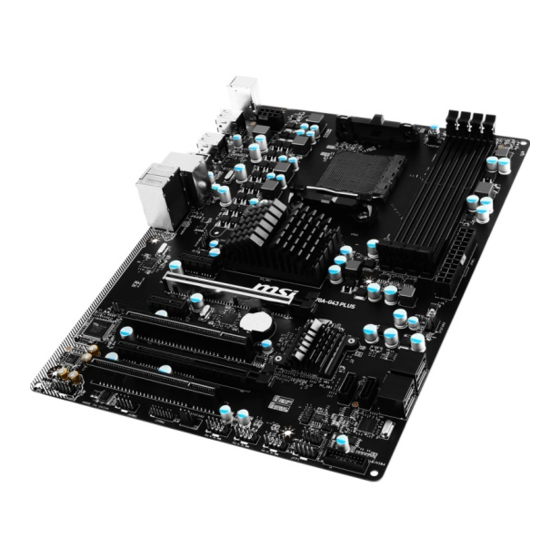
Page 20: Overview Of Components
Overview of Components DIMM3 DIMM2 DIMM4 SYSFAN1 DIMM1 CPUFAN CPU Socket JPWR2 JPWR1 PCI_E1 SYSFAN3 PCI_E2 SATA1 SATA2 PCI_E3 JCI1 SATA5_6 PCI1 SATA3_4 PCI_E4 JBAT1 PCI2 JFP2 JAUD1 JUSB4 JCOM1 JFP1 JTPM1 JUSB3 SYSFAN2 JUSB2 JUSB1 Overview of Components... - Page 21 Component Contents Port Name Port Type Page CPUFAN, SYSFAN1~3 Fan Connectors CPU Socket AM3/ AM3+ CPU Socket DIMM1~4 DIMM Slots JAUD1 Front Audio Connector JBAT1 Clear CMOS (Reset BIOS) Jumper JCI1 Chassis Intrusion Connector JCOM1 Serial Port Connector JFP1, JFP2 Front Panel Connectors JPWR1~2 Power Connectors...
-
Page 22: Cpu Socket
This motherboard is designed to support overclocking. Before attempting to overclock, please make sure that all other system components can tolerate overclocking. Any attempt to operate beyond product specifications is not recommended. MSI does not guarantee the damages or risks caused by ®... -
Page 23: Dimm Slots
DIMM Slots DIMM1 DIMM3 Channel A Channel B DIMM2 DIMM4 Memory module installation recommendation DIMM3 DIMM4 DIMM3 DIMM1 DIMM1 DIMM2 DIMM1 Important Always insert memory modules in the DIMM1 slot first. Due to chipset resource usage, the available capacity of memory will be a little less than the amount of installed. -
Page 24: Pci_E1~4 & Pci1~2: Pcie & Pci Expansion Slots
PCI_E1~E4 & PCI1~2: PCIe & PCI Expansion Slots PCI_E1: PCIe 2.0 x1 slot PCI_E2: PCIe 2.0 x16 slot PCI_E3: PCIe 2.0 x1 slot PCI1: PCI slot PCI_E4: PCIe 2.0 x4 slot PCI2: PCI slot Multiple graphics cards installation recommendation Important For a single PCIe x16 expansion card installation with optimum performance, using the PCI_E2 slot is recommended. -
Page 25: Jaud1: Front Audio Connector
JAUD1: Front Audio Connector This connector allows you to connect audio jacks on the front panel. MIC L Ground MIC R Head Phone R MIC Detection SENSE_SEND No Pin Head Phone L Head Phone Detection SATA1~6: SATA 6Gb/s Connectors These connectors are SATA 6Gb/s interface ports. Each connector can connect to one SATA device. -
Page 26: Jpwr1~2: Power Connectors
JPWR1~2: Power Connectors These connectors allow you to connect an ATX power supply. JPWR2 Ground +12V Ground +12V Ground +12V Ground +12V +3.3V +3.3V +3.3V -12V Ground Ground PS-ON# Ground Ground Ground JPWR1 Ground Ground PWR OK 5VSB +12V +12V +3.3V Ground Important... -
Page 27: Jusb1~3: Usb 2.0 Connectors
JUSB1~3: USB 2.0 Connectors These connectors allow you to connect USB 2.0 ports on the front panel. USB0- USB1- USB0+ USB1+ Ground Ground No Pin Important Note that the VCC and Ground pins must be connected correctly to avoid possible damage. -
Page 28: Jfp1, Jfp2: Front Panel Connectors
JFP1, JFP2: Front Panel Connectors These connectors connect to the switches and LEDs on the front panel. JFP1 HDD LED + Power LED + HDD LED - Power LED - Reset Switch Power Switch Reset Switch Power Switch Reserved No Pin Ground Speaker - Suspend LED... -
Page 29: Jci1: Chassis Intrusion Connector
JCI1: Chassis Intrusion Connector This connector allows you to connect the chassis intrusion switch cable. Normal Trigger the chassis intrusion event (default) Using chassis intrusion detector Connect the JCI1 connector to the chassis intrusion switch/ sensor on the chassis. Close the chassis cover. Go to BIOS >... -
Page 30: Cpufan, Sysfan1~3: Fan Connectors
CPUFAN, SYSFAN1~3: Fan Connectors Fan connectors can be classified as PWM (Pulse Width Modulation) Mode and Voltage Mode. PWM Mode fan connectors provide constant 12V output and adjust fan speed with speed control signal. Voltage Mode fan connectors control fan speed by changing voltage. -
Page 31: Resetting Bios To Default Values
JBAT1: Clear CMOS (Reset BIOS) Jumper There is CMOS memory onboard that is external powered from a battery located on the motherboard to save system configuration data. If you want to clear the system configuration, set the jumper to clear the CMOS memory. Keep Data Clear CMOS/ Reset BIOS... -
Page 32: Bios Setup
Press Delete key, when the Press DEL key to enter Setup Menu, F11 to enter Boot Menu message appears on the screen during the boot process. Use MSI FAST BOOT application. Click on GO2BIOS button and choose OK. The system will reboot and enter BIOS setup directly. -
Page 33: Resetting Bios
Updating BIOS Updating BIOS with M-FLASH Before updating: Please download the latest BIOS file that matches your motherboard model from MSI website. And then save the BIOS file into the USB flash drive. Updating BIOS: Press Del key to enter the BIOS Setup during POST. -
Page 34: Overview
Virtual OC Genie Button - enables or disables the OC Genie function by clicking on this button. When enabled, this button will be light. Enabling OC Genie function can automatically overclock with MSI optimized overclocking profile. Important We recommend that you do not to make any modification in OC menu mode and do not to load defaults after enabling the OC Genie function. -
Page 35: Settings
SETTINGS System Status System Date Sets the system date. Use tab key to switch between date elements. The format is <day> <month> <date> <year>. <day> Day of the week, from Sun to Sat, determined by BIOS. Read-only. <month> The month from Jan. through Dec. <date>... - Page 36 fPCI Latency Timer [32] Sets latency timer of PCI interface device. [Options: 32, 64, 96, 128, 160, 192, 224, 248 PCI Bus clocks] ACPI Settings Sets ACPI parameters of onboard power LED behaviors. Press Enter to enter the sub- menu. fACPI Standby State Specifies the power saving modes for ACPI function.
- Page 37 fSATA Mode [AHCI Mode] Sets the operation mode of the onboard SATA controller. [AHCI Mode] Specify the AHCI mode for SATA storage devices. AHCI (Advanced Host Controller Interface) offers some advanced features to enhance the speed and performance of SATA storage device, such as Native Command Queuing (NCQ) and hot-plugging.
- Page 38 Disables this function. fMSI Fast Boot [Disabled] MSI Fast Boot is the fastest way to boot the system. It will disable more devices to speed up system boot time which is faster than the boot time of Fast Boot. [Enabled] Enables the MSI Fast Boot function to speed up booting time.
- Page 39 Boot [Disabled] Enables or disables the fast boot feature for Windows 8/ 8.1. This item will only be available when MSI Fast Boot is disabled. [Enabled] Enables the Fast Boot configuration to accelerate system boot time. [Disabled] Disables the Fast Boot configuration.
-
Page 40: Boot
fResume From S3/S4/S5 by PS/2 Keyboard [Disabled] Enables or disables the system wake up by PS/2 keyboard. [Any Key] Enables the system to be awakened from S3/ S4/ S5 state when activity of any key on PS/2 keyboard is detected. [Hot Key] Enables the system to be awakened from S3/ S4/ S5 state when activity of hot key on PS/2 keyboard is detected. -
Page 41: Save & Exit
Important When selecting the Administrator / User Password items, a password box will appear on the screen. Type the password then press <Enter>. The password typed now will replace any previous set password from CMOS memory. You will be prompted to confirm the password. - Page 42 Important Overclocking your PC manually is only recommended for advanced users. Overclocking is not guaranteed, and if done improperly, it could void your warranty or severely damage your hardware. If you are unfamiliar with overclocking, we advise you to use OC Genie function for easy overclocking.
- Page 43 CPU Core Control [Auto] This item allows you to select the number of active processor cores. When set to Auto, the CPU will operate under the default number of cores. DRAM Frequency [Auto] Sets the DRAM frequency. Please note the overclocking behavior is not guaranteed. Adjusted DRAM Frequency Shows the adjusted DRAM frequency.
- Page 44 Enter OC and set Unlock CPU Core to Enabled. Set Adjust CPU-NB Ratio and HT Link Speed to [x8]. Save changes and exit the BIOS setup. System restart. Clear CMOS data. Fail Success You will see the “X4” (quad core) or “X2” (dual core for The CPU does not support CPU core unlocking, please leave the default Sempron series only) during POST.
- Page 45 CPU Specifications Press Enter to enter the sub-menu. This sub-menu displays the information of installed CPU. You can also access this information menu at any time by pressing F4. Read only. fCPU Technology Support Press Enter to enter the sub-menu. The sub-menu shows the key features of installed CPU.
-
Page 46: M-Flash
M-FLASH Important M-Flash function allows you to update BIOS from USB flash disk (FAT32/ NTFS format only). Save BIOS to storage Saves the current BIOS file to the USB flash disk. The USB flash disk drive should be in FAT32 format. Update BIOS Selects a BIOS file in the USB flash disk (NTFS/ FAT32 format) to update the BIOS. -
Page 47: Oc Profile
OC PROFILE Overclocking Profile 1/ 2/ 3/ 4/ 5/ 6 Overclocking Profile 1/ 2/ 3/ 4/ 5/ 6 management. Press Enter to enter the sub-menu. fSet Name for Overclocking Profile 1/ 2/ 3/ 4/ 5/ 6 Name the current overclocking profile. fSave Overclocking Profile 1/ 2/ 3/ 4/ 5/ 6 Save the current overclocking profile. -
Page 48: Hardware Monitor
HARDWARE MONITOR Temperature & Speed graphic display Temperature & Speed information control field Voltage display Temperature & Speed information Shows the current CPU temperature, system temperature and fans' speeds. Temperature & Speed graphic display The red graph shows the minimum and maximum temperatures that be set on the Fan control field. -
Page 49: Software Description
Software Description Installing Drivers Start up your computer in Windows 7/ 8.1/ 10. ® Insert MSI Driver Disc into your optical drive. ® The installer will automatically appear and it will find and list all necessary drivers. Click Install button. -
Page 50: Command Center
COMMAND CENTER COMMAND CENTER is an user-friendly software and exclusively developed by MSI, helping users to adjust system settings and monitor status under OS. With the help of COMMAND CENTER, making it possible to achieve easier and efficient monitoring process and adjustments than that under BIOS. In addition, the COMMAND CENTER can be a server for mobile remote control application. - Page 51 CPU Fan CPU Fan control panel provides Smart mode and Manual Mode. You can switch the control mode by clicking the Smart Mode and Manual Mode buttons on the top of the CPU Fan control panel. Manual Mode - allows you to manually control the CPU fan speed by percentage.
- Page 52 Option Buttons - Advanced When click the Advanced button, The Voltage, Fan and DRAM icons will appear. Voltage - allows you to adjust advanced voltage values of CPU and chipset. Fan - allows you to control the system fans speed. DRAM - shows the current Advanced DRAM parameters, and allows you to change the settings by selecting values from the drop-down menu on the right hand side.
- Page 53 Find the IP address on the SoftAP Management Setting area, and enter the IP address on your MSI COMMAND CENTER APP to link your system. ® Press Refresh on the MSI COMMAND CENTER APP to verify that monitoring and ® OC functions are working properly.
-
Page 54: Live Update 6
LIVE UPDATE 6 LIVE UPDATE 6 is an application for the MSI system to scan and download the latest ® drivers, BIOS and utilities. With LIVE UPDATE 6, you don’ t need to search the drivers on websites, and don’ t need to know the models of motherboard and graphics cards. -
Page 55: Total Installer
Choose Automatic scan, system will automatically scan all the items and search for the latest update files. Or you can choose Manual scan and select the items you wish to scan. Click the Scan button at the bottom. It may take several moments to complete the process. -
Page 56: Network Genie
Exit - exits NETWORK GENIE. In case no icon is shown on the system tray, it is possible to activate NETWORK GENIE manually by clicking Start > Programs > MSI > NETWORK GENIE > NETWORK GENIE. NETWORK GENIE Control Panel Mode - allows you to quickly change bandwidth priorities for different applications. - Page 57 Configuring Application’ s Network Priority Go to Application tab. Click L to assign the low network priority to the application, and H to hight. You can also click the Lock icon to block an application network connection. Click the Save button to store your settings. Configuring Network Speed There are two parts in the Advanced tab, one is Internet Speed, and another is Delay/ Sensitivity Settings.
-
Page 58: Raid Configuration
RAID Configuration Below are the different types of a RAID. RAID 0 breaks the data into blocks which are written to separate hard drives. Spreading the hard drive I/O load across independent channels greatly improves I/O performance. RAID 1 provides data redundancy by mirroring data between the hard drives and provides enhanced read performance. - Page 59 Creating RAID Volume Press 2 on the main menu and then press Ctrl + C keys. Then following screen appears. Use the space key to choose a RAID mode (RAID 0/ 1/ 10/ 5) and use the arrow key to move to the Drives Assignments window. Stripe Block Size, the default 64KB is best for RAID 0 or 10.
- Page 60 Important Since you want to create two volumes, this default size (maximum) needs to be reduced. Type in a new size for the first volume. As an example: if you want the first volume to span the first half of the two disks, re-type the size to be half of what is shown by default.
- Page 61 Delete RAID Volume Here you can delete the RAID volume, but please be noted that all data on RAID drives will be lost. Important If your system currently boots to RAID and you delete the RAID volume in the RAID Option ROM, your system will become unbootable.
-
Page 62: Troubleshooting
Troubleshooting Lost BIOS password Before sending the motherboard for RMA repair, try to go over troubleshooting Clear the CMOS, but that will cause guide first to see if your got similar you to lose all customized settings in symptoms as mentioned below. the BIOS. -
Page 63: Regulatory Notices
EU REACH Regulation (Regulation EC No. 1907/2006 of the European Parliament and the This device complies with part 15 of the FCC Rules. Council), MSI provides the information of chemical Operation is subject to the following two conditions: substances in products at: (1) This device may not cause harmful interference, and http://www.msi.com/html/popup/csr/evmtprtt_pcm. - Page 64 MSI will comply with the product take entregar a una empresa autorizada para la recogida de back requirements at the end of life of MSI-branded estos residuos.
- Page 65 MSI si adeguerà a tale Direttiva ritirando tutti i prodotti marchiati MSI che sono stati venduti all’ interno dell’ Unione Europea alla fine del loro ciclo di vita.
- Page 66 Alternatively, please try the following help resources for further guidance. y Visit the MSI website for technical guide, BIOS updates, driver updates, and other information: http://www.msi.com y Register your product at: http://register.msi.com...