Table of Contents
Advertisement
Advertisement
Table of Contents

Related Manuals for MSI 970


Summary of Contents for MSI 970
- Page 1 Preface 970 GAMING Motherboard G52-76931XH...
-
Page 2: Copyright Notice
Copyright Notice The material in this document is the intellectual property of MICRO-STAR INTERNATIONAL. We take every care in the preparation of this document, but no guarantee is given as to the correctness of its contents. Our products are under continual improvement and we reserve the right to make changes without notice. -
Page 3: Technical Support
If a problem arises with your system and no solution can be obtained from the user’s manual, please contact your place of purchase or local distributor. Alternatively, please try the following help resources for further guidance. Visit the MSI website for technical guide, BIOS updates, driver updates, and other information: http://www.msi.com/support/ Contact our technical staff at: http://register.msi.com/... -
Page 4: Safety Instructions
Safety Instructions ■ Always read the safety instructions carefully. ■ Keep this User’s Manual for future reference. ■ Keep this equipment away from humidity. ■ Lay this equipment on a reliable flat surface before setting it up. ■ The openings on the enclosure are for air convection hence protects the equipment from overheating. - Page 5 FCC-B Radio Frequency Interference Statement This equipment has been tested and found to comply with the limits for a Class B digital device, pursuant to Part 15 of the FCC Rules. These limits are designed to provide reasonable protection against harmful interference in a residential installation. This equipment generates, uses and can radiate radio frequency energy and, if not installed and used in accordance with the instructions, may cause harmful interference to radio communications.
- Page 6 Radiation Exposure Statement This equipment complies with FCC radiation exposure limits set forth for an uncontrolled environment. This equipment and its antenna should be installed and operated with minimum distance 20 cm between the radiator and your body. This equipment and its antenna must not be co-located or operating in conjunction with any other antenna or transmitter.
-
Page 7: Battery Information
Replace only with the same or equivalent type recommended by the manufacturer. Chemical Substances Information In compliance with chemical substances regulations, such as the EU REACH Regulation (Regulation EC No. 1907/2006 of the European Parliament and the Council), MSI provides the information of chemical substances in products at: http://www.msi.com/html/popup/csr/evmtprtt_pcm.html Preface... - Page 8 MSI will comply with the product take back requirements at the end of life of MSI-branded products that are sold into the EU. You can return these products to local collection points.
- Page 9 MSI će poštovati zahtev o preuzimanju ovakvih proizvoda kojima je istekao vek trajanja, koji imaju MSI oznaku i koji su prodati u EU. Ove proizvode možete vratiti na lokalnim mestima za prikupljanje.
- Page 10 MSI si adeguerà a tale Direttiva ritirando tutti i prodotti marchiati MSI che sono stati venduti all’interno dell’Unione Europea alla fine del loro ciclo di vita.
- Page 11 2008 № 1057. Việt Nam RoHS Kể từ ngày 01/12/2012, tất cả các sản phẩm do công ty MSI sản xuất tuân thủ Thông tư số 30/2011/TT-BCT quy định tạm thời về giới hạn hàm lượng cho phép của một số...
-
Page 12: Table Of Contents
CONTENTS ▍ Chapter 1 Getting Started................1-1 Packing Contents ....................1-2 Optional Accessories ................... 1-2 Assembly Precautions ..................1-3 Motherboard Specifications .................. 1-4 Connectors Quick Guide ..................1-7 Back Panel Quick Guide ..................1-9 CPU (Central Processing Unit) ................1-11 Introduction to AM3/ AM3+ CPU ..............1-11 CPU &... - Page 13 Chapter 2 Quick Installation ................2-1 CPU Installation ....................2-2 Memory Installation ....................2-4 Motherboard Installation ..................2-5 Power Connectors Installation ................2-7 SATA HDD Installation ..................2-9 Front Panel Connector Installation ..............2-10 JFP1 Connector Installation ................. 2-10 Front Panel Audio Connector Installation ............ 2-10 Peripheral Connector Installation ...............
-
Page 15: Chapter 1 Getting Started
Chapter 1 Getting Started Thank you for choosing the 970 GAMING Series (MS-7693 v4.X) ATX motherboard. The 970 GAMING Series motherboards are based on 970 & SB950 chipset for optimal system efficiency. Designed to ® fit the advanced AMD AM3/ AM3+ processor, the 970 GAMING Series ®... -
Page 16: Packing Contents
Packing Contents Drivers & Utilities Motherboard I/O Shield Motherboard Disc User Guide SATA Cable Optional Accessories USB 3.0 Bracket M-Connector * These pictures are for reference only and may vary without notice. * The packing contents may vary according to the model you purchased. Getting Started... -
Page 17: Assembly Precautions
Assembly Precautions ■ The components included in this package are prone to damage from electrostatic discharge (ESD). Please adhere to the following instructions to ensure successful computer assembly. ■ Always turn off the power supply and unplug the power cord from the power outlet before installing or removing any computer component. -
Page 18: Motherboard Specifications
AM3/ AM3+ socket Hypertransport ■ HyperTransport™ 3.0, supports up to 4.8 GT/s Chipset ■ AMD 970 & SB950 ® Memory ■ 4x DDR3 memory slots supporting up to 32GB ■ Supports DDR3 2133(OC)/ 1866/ 1600/ 1333/ 1066 MHz Support ■... - Page 19 Internal ■ 1x 24-pin ATX main power connector ■ 1x 8-pin ATX 12V power connector Connectors ■ 6x SATA 6Gb/s connectors ■ 3x USB 2.0 connectors (supports additional 6 USB 2.0 ports) ■ 1x USB 3.0 connector (supports additional 2 USB 3.0 ports) ■...
- Page 20 Software ■ Drivers ■ MSI - Command Center - Live Update 5 - Fast Boot ■ 7-ZIP ■ Sound Blaster Cinema 2 ■ Killer Network Manager ■ Norton Internet Security Solution Form Factor ■ ATX Form Factor ■ 12 in. x 9.6 in. (30.5 cm x 24.4 cm) For the latest information about CPU, please visit http://www.msi.com/cpu-support/...
-
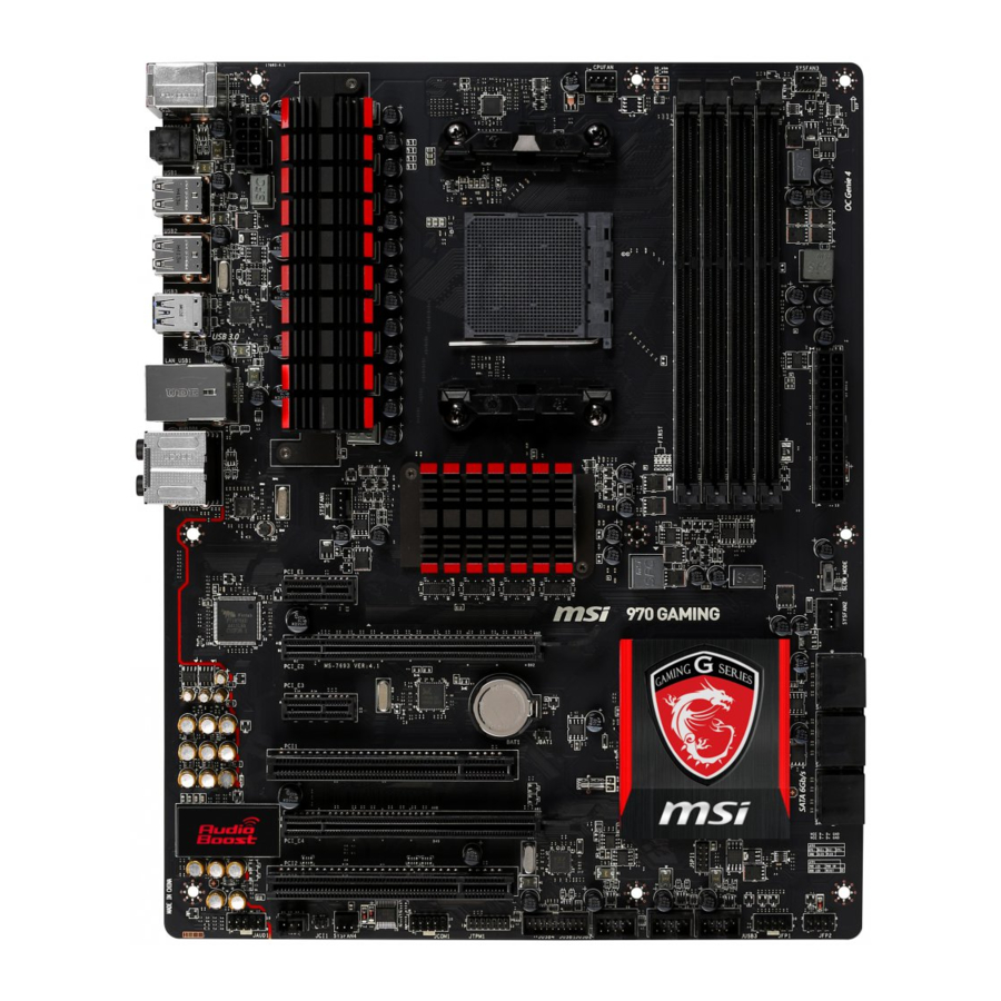
Page 21: Connectors Quick Guide
Connectors Quick Guide DIMM4 JPWR2 DIMM3 SYSFAN3 DIMM2 DIMM1 SYSFAN1 CPUFAN CPU Socket Back Panel JPWR1 SLOW_MODE PCI_E1 SYSFAN2 PCI_E2 SATA5_6 PCI_E3 SATA3_4 PCI1 JBAT1 SATA1_2 PCI_E4 PCI2 JCI1 JFP2 JCOM1 JFP1 JAUD1 JTPM1 JUSB3 SYSFAN4 JUSB2 JUSB4 JSP1 JUSB1 Getting Started... - Page 22 Connectors Reference Guide Port Name Port Type Page Back Panel I/O Ports AM3/ AM3+ Socket 1-11 CPUFAN,SYSFAN1~4 Fan Power Connectors 1-20 DIMM1~4 DDR3 Memory slots 1-14 JAUD1 Front Panel Audio Connector 1-24 JBAT1 Clear CMOS Jumper 1-25 JCI1 Chassis Intrusion Connector 1-23 JCOM1 Serial Port Connector...
-
Page 23: Back Panel Quick Guide
Back Panel Quick Guide PS/2 Keyboard/ LAN Port Mouse combo Port Line-In RS-Out USB 2.0 Port USB 2.0 Port USB 3.0 Port Line-Out CS-Out USB 2.0 Port Optical USB 2.0 Port SS-Out S/PDIF-Out ▶ PS/2 Keyboard/ Mouse combo Port The PS/2 keyboard/ mouse DIN connector for PS/2 keyboard/ mouse. - Page 24 ▶ LAN Port The standard RJ-45 LAN jack is for connecting to a Local Area Network (LAN). LED Status Description No link Link/ Activity LED Yellow Linked LINK/ACT SPEED Blinking Data activity 10 Mbps connection Speed LED Green 100 Mbps connection Orange 1 Gbps connection ▶...
-
Page 25: Cpu (Central Processing Unit)
This motherboard is designed to support overclocking. Before attempting to overclock, please make sure that all other system components can tolerate overclocking. Any attempt to operate beyond product specifications is not recommend. MSI does not guarantee the damages or risks caused by inadequate operation beyond product specifications. -
Page 26: Cpu & Cooler Installation
CPU & Cooler Installation When you are installing the CPU, make sure the CPU has a cooler attached on the top to prevent overheating. Meanwhile, do not forget to apply some thermal paste on CPU before installing the heat sink/cooler fan for better heat dispersion. Follow the steps below to install the CPU &... - Page 27 5. Locate the CPU fan connector on the motherboard. 6. Position the cooling set onto the retention mechanism. Hook one end of the clip to hook first. CPU fan connector 7. Then press down the other end of the clip to fasten the cooling set on the top of the retention mechanism.
-
Page 28: Memory
Memory These DIMM slots are used for installing memory modules. DIMM1 DIMM2 DIMM3 DIMM4 Video Demonstration Watch the video to learn how to install memories. http://youtu.be/76yLtJaKlCQ Dual-Channel mode Population Rule In Dual-Channel mode, the memory modules can transmit and receive data with two data bus channels simultaneously. -
Page 29: Mounting Screw Holes
Mounting Screw Holes When installing the motherboard, first install the necessary mounting stands required for an motherboard on the mounting plate in your computer case. If there is an I/O back plate that came with the computer case, please replace it with the I/O backplate that came with the motherboard package. -
Page 30: Power Supply
Power Supply Video Demonstration Watch the video to learn how to install power supply connectors. http://youtu.be/gkDYyR_83I4 JPWR1~2: ATX Power Connectors These connectors allow you to connect an ATX power supply. To connect the ATX power supply, align the power supply cable with the connector and firmly press the cable into the connector. -
Page 31: Expansion Slots
Expansion Slots This motherboard contains numerous slots for expansion cards, such as discrete graphics or audio cards. PCI_E1~4: PCIe Expansion Slots The PCIe slot supports the PCIe interface expansion card. PCIe x16 Slot PCIe x1 Slot PCI1~2: PCI Expansion Slots The PCI slot supports additional LAN, SCSI, USB, and other add-on cards that comply with PCI specifications. -
Page 32: Video/ Graphics Cards
Adding on one or more discrete video cards will significantly boost the system’s graphics performance. For best compatibility, MSI graphics cards are recommended. Video Demonstration Watch the video to learn how to install a graphics card on PCIe x16 slot with butterfly lock. -
Page 33: Internal Connectors
Internal Connectors SATA1~6: SATA Connectors This connector is a high-speed SATA interface port. Each connector can connect to one SATA device. SATA devices include disk drives (HDD), solid state drives (SSD), and optical drives (CD/ DVD/ Blu-Ray). Video Demonstration Watch the video to learn how to Install SATA HDD. http://youtu.be/RZsMpqxythc SATA6 SATA4... -
Page 34: Cpufan,Sysfan1~4: Fan Power Connectors
CPUFAN,SYSFAN1~4: Fan Power Connectors The fan power connectors support system cooling fans with +12V. If the motherboard has a System Hardware Monitor chipset on-board, you must use a specially designed fan with a speed sensor to take advantage of the CPU fan control. Remember to connect all system fans. -
Page 35: Jfp1, Jfp2: System Panel Connectors
JFP1, JFP2: System Panel Connectors These connectors connect to the front panel switches and LEDs. When installing the front panel connectors, please use the optional M-Connector to simplify installation. Plug all the wires from the computer case into the M-Connector and then plug the M- Connector into the motherboard. -
Page 36: Jusb1~3: Usb 2.0 Expansion Connectors
JUSB1~3: USB 2.0 Expansion Connectors This connector is designed for connecting high-speed USB peripherals such as USB HDDs, digital cameras, MP3 players, printers, modems, and many others. Important Note that the VCC and GND pins must be connected correctly to avoid possible damage. -
Page 37: Jci1: Chassis Intrusion Connector
JCI1: Chassis Intrusion Connector This connector connects to the chassis intrusion switch cable. If the computer case is opened, the chassis intrusion mechanism will be activated. The system will record this intrusion and a warning message will flash on screen. To clear the warning, you must enter the BIOS utility and clear the record. -
Page 38: Jcom1: Serial Port Connector
JCOM1: Serial Port Connector This connector is a 16550A high speed communication port that sends/receives 16 bytes FIFOs. You can attach a serial device. JAUD1: Front Panel Audio Connector This connector allows you to connect the front audio panel located on your computer case. -
Page 39: Jumper
Jumper JBAT1: Clear CMOS Jumper There is CMOS RAM onboard that is external powered from a battery located on the motherboard to save system configuration data. With the CMOS RAM, the system can automatically boot into the operating system (OS) every time it is turned on. If you want to clear the system configuration, set the jumpers to clear the CMOS RAM. -
Page 40: Switch
Switch SLOW_MODE: Slow Mode Booting Switch This switch is used for LN2 cooling solution, that provides the extreme overclocking conditions, to boot at a stable processor frequency and to prevent the system from crashing. Enabled Normal (Default) Important Users will try extreme low temperature overclocking at their own risks. The overclocking results will vary according to the CPU version. -
Page 41: Drivers And Utilities
After you install the operating system you will need to install drivers to maximize the performance of the new computer you just built. MSI motherboard comes with a Driver Disc. Drivers allow the computer to utilize your motherboard more efficiently and take advantage of any special features we provide. - Page 43 Chapter 2 Quick Installation This chapter provides demonstration diagrams about how to install your computer. Some of the installations also provide video demonstrations. Please link to the URL to watch it with the web browser on your phone or tablet. You may have even link to the URL by scanning the QR code. Important The diagrams in this chapter are for reference only and may vary from the product you purchased.
- Page 44 CPU Installation Quick Installation...
-
Page 45: Chapter 2 Quick Installation
Quick Installation... -
Page 46: Memory Installation
Memory Installation http://youtu.be/76yLtJaKlCQ Quick Installation... -
Page 47: Motherboard Installation
Motherboard Installation Quick Installation... - Page 48 Quick Installation...
-
Page 49: Power Connectors Installation
Power Connectors Installation http://youtu.be/gkDYyR_83I4 Quick Installation... - Page 50 Quick Installation...
-
Page 51: Sata Hdd Installation
SATA HDD Installation http://youtu.be/RZsMpqxythc Quick Installation... -
Page 52: Front Panel Connector Installation
Front Panel Connector Installation JFP1 Connector Installation http://youtu.be/DPELIdVNZUI Front Panel Audio Connector Installation Quick Installation 2-10... -
Page 53: Peripheral Connector Installation
Peripheral Connector Installation USB2.0 Connector Installation USB3.0 Connector Installation 2-11 Quick Installation... -
Page 54: Graphics Card Installation
Graphics Card Installation http://youtu.be/mG0GZpr9w_A Quick Installation 2-12... - Page 55 2-13 Quick Installation...
-
Page 57: Chapter 3 Bios Setup
Chapter 3 BIOS Setup CLICK BIOS is a revolutionary UEFI interface that allows you to setup and configure your system for optimum use. Using your mouse and keyboard, users can change BIOS settings, monitor CPU temperature, select the boot device priority and view system information such as the CPU name, DRAM capacity, the OS version and the BIOS version. -
Page 58: Entering Setup
(optional) on the motherboard to enable the system going to BIOS setup directly at next boot. Click "GO2BIOS" tab on "MSI Fast Boot" utility screen. Important Please be sure to install the “MSI Fast Boot” utility before using it to enter the BIOS setup. BIOS Setup... -
Page 59: Overview
Overview After entering BIOS, the following screen is displayed. Temperature monitor Language System information Virtual OC Genie Button Boot device priority bar BIOS menu selection BIOS menu selection Menu display ▶ BIOS menu selection The following options are available: ■ SETTINGS - Uses this menu to specify the parameters for chipset and boot devices. - Page 60 Enables or disables the OC Genie function by clicking on this button. When enabled, this button will be light. Enabling OC Genie function can automatically overclock with MSI optimized overclocking profile. Important We recommend that you do not to make any modification in OC menu mode and do not to load defaults after enabling the OC Genie function.
-
Page 61: Operation
Operation You can control BIOS settings with the mouse and the keyboard. The following table lists and describes the hot keys and the mouse operations. Hot key Mouse Description <↑↓→← > Select Item Move the cursor <Enter> Select Icon/ Field Click/ Double-click the left button <Esc>... -
Page 62: Settings
SETTINGS System Status ▶ System Date Sets the system date. Use tab key to switch between date elements. The format is <day> <month> <date> <year>. <day> Day of the week, from Sun to Sat, determined by BIOS. Read-only. <month> The month from Jan. through Dec. <date>... -
Page 63: Advanced
Advanced ▶ PCI Subsystem Settings Sets PCI Express interface protocol and latency timer. Press <Enter> to enter the sub-menu. ▶ PCI Latency Timer [32] Sets latency timer of PCI interface device. [Options: 32, 64, 96, 128, 160, 192, 224, 248 PCI Bus clocks] ▶... - Page 64 ▶ SATA Mode [AHCI Mode] Sets the operation mode of the onboard SATA controller. The default mode is AHCI. [Disabled] Disables the SATA function. [IDE Mode] Specify the IDE mode for SATA storage devices. [AHCI Mode] Specify the AHCI mode for SATA storage devices. AHCI (Advanced Host Controller Interface) offers some advanced features to enhance the speed and performance of SATA storage device, such as Native Command Queuing (NCQ) and hot-plugging.
- Page 65 Disables this function. ▶ MSI Fast Boot [Disabled] MSI Fast Boot is the fastest way to boot the system. It will disable more devices to speed up system boot time which is faster than the boot time of “Fast Boot” .
- Page 66 Important If you want to enter BIOS with enabled “MSI Fast Boot” mode or enabled "Fast Boot" mode, you have to click the "GO2BIOS" tab on MSI Fast Boot utility screen or press the "GO2BIOS" button (optional) on the motherboard. And then the system will enter to BIOS setup directly at next boot.
-
Page 67: Boot
▶ Resume From S3/S4/S5 by PS/2 Keyboard [Disabled] Disables or enables the system wake up by PS/2 keyboard. [Any Key] Enables the system to be awakened from S3/ S4/ S5 state when activity of any key on PS/2 keyboard is detected. [Hot Key] Enables the system to be awakened from S3/ S4/ S5 state when activity of hot key on PS/2 keyboard is detected. -
Page 68: Save & Exit
▶ Chassis Intrusion Configuration Press <Enter> to enter the sub-menu. ▶ Chassis Intrusion [Disabled] This function will be available if the chassis equips a chassis intrusion switch. Once the chassis is opened, the system will record and issue a warning message. To clear the warning message, set the item to [Reset], then it will return to [Enabled] later. - Page 69 Important • Overclocking your PC manually is only recommended for advanced users. • Overclocking is not guaranteed, and if done improperly, can void your warranty or severely damage your hardware. • If you are unfamiliar with overclocking, we advise you to use OC Genie for easy overclocking.
- Page 70 ▶ AMD Turbo Core Technology [Auto] Based on AMD Turbo Core Technology, part of CPU core ratio may pop down for providing more performance headroom for active CPU core, even AMD Cool’n’Quiet Technology is Disabled. [Auto] Turbo Core Technology will linked to AMD Cool’n’Quiet Technology. [Enabled] Enables this function.
- Page 71 ▶ HT Link Speed This item allows you to set the Hyper-Transport Link speed. Setting to [Auto], the system will detect the HT link speed automatically. ▶ Adjusted HT Link Frequency It shows the adjusted HT Link frequency. Read-only. ▶ HT Link Control Press <Enter>...
- Page 72 ▶ AMD Cool’n’Quiet [Auto] Enabled or disabled AMD Cool’n’Quiet function. [Auto] Depends on AMD Design. [Enable] Enables AMD Cool’n’Quiet function. The Cool’n’Quiet technology can effectively and dynamically lower CPU speed and power consumption. [Disabled] Disables this function. Important When adjusting CPU Ratio, the Cool’n’Quiet function will be disabled automatically. For CPU which supports the Turbo Core Tech., please set AMD Turbo Core Technology and AMD Cool’n’Quiet as Disabled to retain the default CPU core speed.
-
Page 73: M-Flash
M-FLASH Important M-Flash funcion allows you to update BIOS from USB flash disk (FAT32/ NTFS format only). ▶ Save BIOS to storage Saves the current BIOS file to the USB flash disk. The USB flash disk drive should be in FAT32 format. ▶... -
Page 74: Oc Profile
OC PROFILE ▶ Overclocking Profile 1/ 2/ 3/ 4/ 5/ 6 Overclocking Profile 1/ 2/ 3/ 4/ 5/ 6 management. Press <Enter> to enter the sub- menu. ▶ Set Name for Overclocking Profile 1/ 2/ 3/ 4/ 5/ 6 Names the current overclocking profile. ▶... -
Page 75: Hardware Monitor
HARDWARE MONITOR Current Temperature & Temperature & Speed Speed information graphic display control field Voltage display ▶ Current Temperature & Speed information Shows the current CPU temperature, system temperature and fans' speeds. ▶ Temperature & Speed graphic display The red graph shows the minimum and maximum temperatures that be set on the “Fan control field”. - Page 76 Please follow the description below to set the temperatures and fan speeds. ■ a - Selects a fan you want to specify the speed. ■ b - Checks this item to activate the following items for changing default values. ■ c - Slides the Min and Max tabs to set the minimum and maximum temperatures.
-
Page 77: Appendix A Realtek Audio
Appendix A Realtek Audio The Realtek audio provides 10-channel DAC that simultaneously supports 7.1 sound playback and 2 channels of independent stereo sound output (multiple streaming) through the Front-Out-Left and Front-Out-Right channels. -
Page 78: Software Configuration
Software Configuration After installing the audio driver (see Chapter 1 - Driver and Utilities), the “Realtek HD Audio Manager” icon will appear at the notification area (lower right of the screen). You may double click the icon and the GUI will pop up accordingly. double click the icon It is also available to enable the audio driver by clicking the Realtek HD Audio Manager from the Control Panel. -
Page 79: Auto Popup Dialog
▶ Device Selection Here you can select a audio output source to change the related options. The “check” sign indicates the devices as default. ▶ Volume Adjustment You can control the volume or balance the right/left side of the speakers that you plugged in front or rear panel by adjust the bar. -
Page 80: Hardware Default Setting
Hardware Default Setting The following diagrams are audio back panel default setting. ■ Backpanel audio jacks to 2-channel speakers diagram F r o ■ Backpanel audio jacks to 4-channel speakers diagram F r o R e a Realtek Audio... - Page 81 ■ Backpanel audio jacks to 6-channel speakers diagram F r o C e n R e a t e r & S u b w o o f ■ Backpanel audio jacks to 8-channel speakers diagram F r o C e n R e a t e r &...
-
Page 83: Appendix B Amd Raid
Appendix B AMD RAID This appendix will assist users in configuring and enabling RAID functionality. -
Page 84: Raid Configuration
RAID Configuration Creating and deleting RAID set and performing other RAID setting up operations are done in the RAID BIOS. During boot-up, a screen similar to the one below will appear for about few seconds. Press <Ctrl-F> to enter RAID Option ROM utility. Press <Ctrl-F>... - Page 85 View Drives Assignments This window displays the model number, capacities and assignment of the drives physically attached to the SATA host adapter. AMD RAID...
- Page 86 LD View / LD Define Menu (Creating RAID) The selection of the RAID configuration should be based upon factors including performance, data security, and the number of drives available. It is best to carefully consider the long-term role of the system and plan the data storage strategy. RAID sets can be created either automatically, or to allow the greatest flexibility, manually.
- Page 87 ■ Stripe Block Size, the default 64KB is best for most applications. RAID 0 or 10 only. ■ Gigabyte Boundary, allows use of slightly smaller replacement drives. 3. On the Drives Assignments window, use the arrow key to choose the hard drives which you want to make part of the LD, use the space key to change the assignment to “Y”.
- Page 88 6. The message will show up on the bottom, press any key to use maximum capacity or press [Ctrl-Y] to modify array capacity manually. Important • The default capacity is the full capacity of the selected hard drives. • If you allocate the first LD capacity manually, you can create second LD with remaining capacity of the selected hard drives.
- Page 89 Delete LD Menu (Deleting RAID) 1. Press “3” on the main to enter the Delete LD Menu. 2. Choose a LD No. you want to delete and press [Del] or [Alt+D] delete the RAID set. 3. On the next screen, a message will display to inform you, press “Ctrl+Y” to delete the RAID set or other key to abort it.
-
Page 90: Installing Driver
Please follow the instruction below to make an “AMD RAID Driver” for yourself. ® • Insert the MSI Driver Disc into the optical drive. • Click the “Browse CD” on the Setup screen. • Copy all the contents in - ChipSet\W7_W8\Packages\Drivers\SBDrv\SB9xx\RAID •...