Table of Contents
Advertisement
Available languages
Available languages
Advertisement
Table of Contents

Related Manuals for MSI 970A-G45 series


Summary of Contents for MSI 970A-G45 series
- Page 1 970A-G45 series MS-7693 (v1.x) Mainboard G52-76931X3...
-
Page 2: Trademarks
Alternatively, please try the following help resources for further guidance. ◙ Visit the MSI website for technical guide, BIOS updates, driver updates, and other information: http://www.msi.com/service/download ◙ Contact our technical staff at: http://support.msi.com... -
Page 3: Safety Instructions
MS-7693 MS-7693 Safety Instructions ■ Always read the safety instructions carefully. ■ Keep this User’s Manual for future reference. ■ Keep this equipment away from humidity. ■ Lay this equipment on a reliable flat surface before setting it up. ■ The openings on the enclosure are for air convection hence protects the equipment from overheating. -
Page 4: Fcc-B Radio Frequency Interference Statement
Preface Preface FCC-B Radio Frequency Interference Statement This equipment has been tested and found to comply with the limits for a Class B digi- tal device, pursuant to Part 15 of the FCC Rules. These limits are designed to provide reasonable protection against harmful inter- ference in a residential installation. -
Page 5: Weee (Waste Electrical And Electronic Equipment) Statement
MSI will comply with the product take back requirements at the end of life of MSI-branded prod- ucts that are sold into the EU. - Page 6 MSI će poštovati zahtev o preuzimanju ovakvih proizvoda kojima je istekao vek trajanja, koji imaju MSI oznaku i koji su prodati u EU. Ove proiz- vode možete vratiti na lokalnim mestima za prikupljanje.
- Page 7 MSI si adeguerà a tale Direttiva ritirando tutti i prodotti marchiati MSI che sono stati venduti all’interno dell’Unione Europea alla fine del loro...
-
Page 8: Table Of Contents
Preface Preface Contents Copyright Notice .................... ii Trademarks ....................ii Revision History..................... ii Technical Support..................ii Safety Instructions ..................iii FCC-B Radio Frequency Interference Statement.......... iv WEEE (Waste Electrical and Electronic Equipment) Statement ....v English ...................... En-1 Mainboard Specifications ...................En-2 Quick Components Guide ..................En-4 Mounting Screw Holes ..................En-5 CPU (Central Processing Unit) ................En-6... - Page 9 MS-7693 MS-7693 Français ..................... Fr-1 Spécifications ......................Fr-2 Guide Rapide Des Composants ................Fr-4 Trous Taraudés de Montage ................Fr-5 Processeur : CPU ....................Fr-6 Mémoire ......................Fr-9 Connecteurs d’alimentation ................Fr-11 Panneau arrière ....................Fr-12 Connecteurs ......................Fr-14 Cavalier ......................Fr-19 Emplacements ....................Fr-20 Indicateurs de Statut LED .................Fr-21 Réglage BIOS ....................Fr-22 Information Logiciel ...................Fr-32 Русский...
-
Page 11: English
English 970A-G45 Series Europe version... -
Page 12: Mainboard Specifications
Mainboard Specifications Processor Support ■ Phenom II, Athlon and Sempron processor in the AM3/ AM3+ package. ® (For the latest information about CPU, please visit http://www.msi.com/service/cpu-support) HyperTransport ■ HyperTransport™ 3.0, supports up to 4.8 GT/s Chipset ■ 970 & SB950 ®... - Page 13 ATX (22.5 cm X 30.5 cm) Mounting screw holes ■ 6 mounting screw holes If you need to purchase accessories and request the part numbers, you could search the product web page and find details on our web address below http://www.msi.com/index.php En-3...
-
Page 14: Quick Components Guide
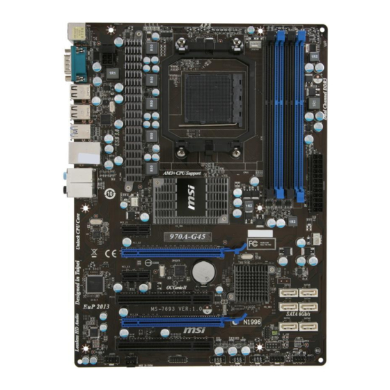
MS-7693 Mainboard Quick Components Guide CPUFAN, En-15 SYSFAN1, En-15 CPU, En-6 JPWR2, En-11 DDR3, En-9 Back Panel, En-12 JPWR1, En-11 PCIE, En-20 SYSFAN2, En-15 JCI1, En-15 SATA, En-14 PCI, En-20 JBAT1, En-19 JAUD1, En-17 JTPM1, En-18 JFP1/ JFP2, En-16 JSP1, En-16 JUSB1~3, En-17 En-4... -
Page 15: Mounting Screw Holes
Mounting Screw Holes When you install the mainboard, you have to place the mainboard into the chassis in the correct direction. The locations of screws holes on the mainboard are shown as below. The side has to toward the rear, the position for the I/O shield of the chassis. -
Page 16: Cpu (Central Processing Unit
When you are installing the CPU, make sure to install the cooler to prevent overheating. If you do not have the CPU cooler, consult your dealer before turning on the computer. For the latest information about CPU, please visit http://www.msi.com/service/cpu-support Important Overheating Overheating will seriously damage the CPU and system. - Page 17 CPU & Cooler Installation When you are installing the CPU, make sure the CPU has a cooler attached on the top to prevent overheating. Meanwhile, do not forget to apply some thermal paste on CPU before installing the heat sink/cooler fan for better heat dispersion. Follow the steps below to install the CPU &...
- Page 18 MS-7693 Mainboard Position the cooling set onto the re- Then press down the other end of the tention mechanism. clip to fasten the cooling set on the Hook one end of the clip to hook top of the retention mechanism. first.
-
Page 19: Memory
Memory These DIMM slots are used for installing memory modules. For more information on compatible components, please visit http://www.msi.com/service/test-report DDR3 240-pin, 1.5V 72x2=144 pin 48x2=96 pin Dual-Channel mode Population Rule In Dual-Channel mode, the memory modules can transmit and receive data with two data bus lines simultaneously. -
Page 20: Installing Memory Modules
MS-7693 Mainboard Installing Memory Modules The memory module has only one notch on the center and will only fit in the right orientation. Insert the memory module vertically into the DIMM slot. Then push it in until the golden finger on the memory module is deeply inserted in the DIMM slot. The plastic clip at each side of the DIMM slot will automatically close when the memory module is properly seated. -
Page 21: Power Supply
Power Supply ATX 24-pin Power Connector: JPWR1 This connector allows you to connect an ATX 24-pin power supply. To connect the ATX 24-pin power supply, make sure the plug of the power supply is inserted in the proper orientation and the pins are aligned. Then push down the power supply firmly into the connector. -
Page 22: Back Panel
MS-7693 Mainboard Back Panel Optical S/PDIF-Out Line-In RS-Out USB 2.0 Port USB 2.0 Port Serial Port Line-Out CS-Out SS-Out Mouse/Keyboard USB 3.0 Port USB 2.0 Port ▶ Optical S/PDIF-Out This S/PDIF (Sony & Philips Digital Interconnect Format) connector is provided for digital audio transmission to external speakers through an optical fiber cable. - Page 23 ▶ The standard RJ-45 LAN jack is for connection to Yellow Green/ Orange the Local Area Network (LAN). You can connect a network cable to it. Color LED State Condition Left Yellow LAN link is NOT established. On(Steady state) LAN link is established. On(brighter &...
-
Page 24: Connectors
MS-7693 Mainboard Connectors Serial ATA Connector: SATA1~6 This connector is a high-speed Serial ATA interface port. Each connector can connect to one Serial ATA device. * The MB layout in this figure is for reference only. SATA5 SATA3 SATA1 SATA6 SATA4 SATA2 Important... - Page 25 Fan Power Connectors: CPUFAN, SYSFAN1, SYSFAN2 The fan power connectors support system cooling fan with +12V. When connecting the wire to the connectors, always note that the red wire is the positive and should be connected to the +12V; the black wire is Ground and should be connected to GND. If the mainboard has a System Hardware Monitor chipset on-board, you must use a specially designed fan with speed sensor to take advantage of the CPU fan control.
- Page 26 MS-7693 Mainboard Front Panel Connectors: JFP1, JFP2 These connectors are for electrical connection to the front panel switches and LEDs. The JFP1 is compliant with Intel Front Panel I/O Connectivity Design Guide. ® JFP2 JFP1 S/PDIF-Out Connector: JSP1 This connector is used to connect S/PDIF (Sony & Philips Digital Interconnect Format) interface for digital audio transmission.
- Page 27 Front USB Connector: JUSB1 / JUSB2 / JUSB3 This connector, compliant with Intel I/O Connectivity Design Guide, is ideal for ® connecting high-speed USB interface peripherals such as USB HDD, digital cameras, MP3 players, printers, modems and the like. * The MB layout in this figure is for reference only. USB 2.0 Bracket (optional) Important Note that the pins of VCC and GND must be connected correctly to avoid possible...
- Page 28 MS-7693 Mainboard TPM Module connector: JTPM1 This connector connects to a TPM (Trusted Platform Module) module (optional). Please refer to the TPM security platform manual for more details and usages. TPM module is optional * The MB layout in this figure is for reference only. En-18...
-
Page 29: Jumper
Jumper Clear CMOS Jumper: JBAT1 There is a CMOS RAM onboard that has a power supply from an external battery to keep the data of system configuration. With the CMOS RAM, the system can automatically boot OS every time it is turned on. If you want to clear the system configuration, set the jumper to clear data. -
Page 30: Slots
MS-7693 Mainboard Slots PCIe Slot The PCIe slot supports the PCIe interface expansion card. PCIe x16 Slot PCIe x1 Slot PCI (Peripheral Component Interconnect) Slot The PCI slot supports LAN card, SCSI card, USB card, and other add-on cards that comply with PCI specifications. -
Page 31: Led Status Indicators
LED Status Indicators CPU Phase LED CPU Phase LED These LEDs indicate the current CPU power phase mode. Follow the instructions below to read. Lights CPU is in 1 phase power mode. CPU is in 2 phase power mode. CPU is in 3 phase power mode. CPU is in 4 phase power mode. -
Page 32: Bios Setup
MS-7693 Mainboard BIOS Setup This chapter provides basic information on the BIOS Setup program and allows you to configure the system for optimum use. You may need to run the Setup program when: ■ An error message appears on the screen during the system booting up, and requests you to run BIOS SETUP. - Page 33 Control Keyboard Mouse Description <↑><↓> Select Item <←><→> Select Screen Move the cursor <Enter> Select Icon/ Field Click/ Double- click the left button <Esc> Jumps to the Exit menu or returns to the previous from a submenu Click the right button <+>...
- Page 34 MS-7693 Mainboard The Menu Bar ▶ Main Menu Use this menu for basic system configurations, such as time, date etc. ▶ Advanced Use this menu to setup the items of the BIOS special enhanced features, integrated peripherals, power management and PC health status. ▶...
- Page 35 After entering the BIOS Setup utility, follow the processes below for general use. Load Optimized Defaults : Use the arrow keys (←, →, ↑, ↓) to select the [Restore Defaults] in [Save & Exit] menu, and press <Enter>. A pop-up message will appear, please select [Yes] and press<Enter>...
- Page 36 MS-7693 Mainboard Overclocking This menu is for advanced users who want to overclock the mainboard. ▶ Current CPU / DRAM Frequency These items show the current clocks of CPU and Memory speed. Read-only. ▶ Adjust CPU FSB Frequency This item is used to adjust the CPU FSB frequency (in MHz). ▶...
- Page 37 ▶ Unlock CPU Core This item is used to unlock the CPU core. Please refer to the procedures below for CPU core unlocked in BIOS setup. Enter “Overclocking” and set “Unlock CPU Core” to [Enabled]. Set “Adjust CPU-NB Ratio” and “HT Link Speed”...
- Page 38 MS-7693 Mainboard ▶ DRAM Frequency This item is used to adjust the DRAM frequency. Setting to [Auto], the system will detect the DRAM Frequency automatically. ▶ Adjusted DRAM Frequency It shows the adjusted Memory frequency. Read-only. ▶ DRAM Timing Mode This field has the capacity to automatically detect the DRAM timing.
- Page 39 ▶ tWTR Minimum time interval between the end of write data burst and the start of a column- read command. It allows I/O gating to overdrive sense amplifiers before read command starts. ▶ tRFC This setting determines the time RFC takes to read from and write to a memory cell.
- Page 40 MS-7693 Mainboard The greater the Spread Spectrum value is, the greater the EMI is reduced, and the • system will become less stable. For the most suitable Spread Spectrum value, please consult your local EMI regulation. • Remember to disable Spread Spectrum if you are overclocking because even a slight jitter can introduce a temporary boost in clock speed which may just cause your overclocked processor to lock up.
- Page 41 ▶ C1E Support Enable this item to reduce the CPU power consumption while idle. Not all processors support Enhanced Halt state (C1E). ▶ SVM Mode This item allows you to enable/disable the AMD SVM (Secure Virtual Machine) Mode. ▶ IOMMU Mode This item allows you to enable/disable the IOMMU (I/O Memory Management Unit) for I/O virtualization.
-
Page 42: Software Information
Product info menu : It shows the newly information of MSI product. Security menu : It provides the useful antivirus program. Important Please visit the MSI officially website to get the latest drivers and BIOS for better system performance. En-32... -
Page 43: Deutsch
Deutsch 970A-G45 Serie Europa Version... -
Page 44: Spezifikationen
DDR3 2133*(OC)/ 1866/ 1600/ 1333/ 1066 SDRAM (gesamt max.32 GB) ■ 4 DDR3 DIMMs (240-Pin/ 1,5V) (* OC= Übertaktung, weitere Informationen zu kompatiblen Speichermodulen finden Sie unter http://www.msi.com/service/test-report) ■ Unterstützt LAN 10/ 100/ 1000 Fast Ethernet über Realtek RTL8111E ®... - Page 45 2 PCI-Steckplätze, unterstützen 3,3V/ 5V PCI Bus Interface Form Faktor ■ ATX (22,5 cm X 30,5 cm) Schraubenlöcher für die Montage ■ 6 Schraubenlöcher für die Montage Wenn Sie für Bestellungen von Zubehör Teilenummern benötigen, finden Sie diese auf unserer Produktseite unter http://www.msi.com/index.php De-3...
-
Page 46: Komponenten-Übersicht
MS-7693 Mainboard Komponenten-Übersicht CPUFAN, De-15 SYSFAN1, De-15 CPU, De-6 JPWR2, De-11 DDR3, De-9 Rücktafel, De-12 JPWR1, De-11 PCIE, De-20 SYSFAN2, De-15 JCI1, De-15 SATA, De-14 PCI, De-20 JBAT1, De-19 JAUD1, De-17 JTPM1, De-18 JFP1/ JFP2, De-16 JSP1, De-16 JUSB1~3, De-17 De-4... -
Page 47: Schraubenlöcher Für Die Montage
Schraubenlöcher für die Montage Wenn Sie das Mainboard zu installieren, müssen Sie das Mainboard in das Chassis in der korrekten Richtung setzen. Die Standorte von Schraubenlöchern auf dem Main- board sind wie nachfolgend gezeigt. Die Seite muss nach hinten, die Position für E/A-Abschirmung des Chassis. -
Page 48: Cpu (Central Processing Unit
Sie sich bitte mit Ihrem Händler in Verbindung, um einen solchen zu erwerben und zu installieren. Um die neuesten Informationen zu unterstützten Prozessoren zu erhalten, besuchen Sie bitte http://www.msi.com/service/cpu-support Wichtig Überhitzung Überhitzung beschädigt die CPU und das System nachhaltig. Stellen Sie stets eine korrekte Funktionsweise des CPU Kühlers sicher, um die CPU vor Überhitzung zu... - Page 49 CPU & Kühler Einbau Wenn Sie die CPU einbauen, stellen Sie bitte sicher, dass Sie auf der CPU einen Kühler anbringen, um Überhitzung zu vermeiden. Vergessen Sie nicht, etwas Siliziumwärmel- eitpaste auf die CPU aufzutragen, bevor Sie den Prozessorkühler installieren, um eine Ableitung der Hitze zu erzielen.
- Page 50 MS-7693 Mainboard Setzen Sie den Kühler auf die Dann drücken Sie das andere Ende Kühlerhalterung und hacken Sie zu- des Bügels herunter, um den Kühler erst ein Ende des Kühlers an dem auf der Kühlerhalterung zu fixieren . Modul fest. Anschließend ziehen Sie den Sicher- ungshebel an der Seite fest.
-
Page 51: Speicher
Speicher Diese DIMM-Steckplätze nehmen Arbeitsspeichermodule auf. Die neusten Informa- tionen über kompatible Bauteile finden Sie unter http://www.msi.com/service/test- report DDR3 240-polig, 1,5V 72x2=144 Pole 48x2=96 Pole Populationsregeln für Dual-Kanal-Speicher Im Dual-Kanal-Modus können Arbeitsspeichermodule Daten über zwei Datenbusleitun- gen gleichzeitig senden und empfangen. Durch Aktivierung des Dual-Kanal-Modus wird die Leistung Ihres Systems verbessert. - Page 52 MS-7693 Mainboard Vorgehensweise beim Einbau von Speicher Modulen Die Speichermodulen haben nur eine Kerbe in der Mitte des Moduls. Sie passen nur in einer Richtung in den Sockel. Stecken Sie das Arbeitsspeichermodul senkrecht in den DIMM-Steckplatz ein. Drücken Sie anschließnd das Arbeitsspeichermodul nach unten, bis die Kontakt- seite richtig tief in dem DIMM-Steckplatz sitzt.
-
Page 53: Stromversorgung
Stromversorgung ATX 24-poliger Stromanschluss: JPWR1 Mit diesem Anschluss verbinden Sie den ATX 24-poligen Anschluss des Netzteils. Achten Sie bei dem Verbinden des ATX 24-poligen Stromanschlusses darauf, dass der Anschluss des Netzteils richtig auf den Anschluss an der Hauptplatine ausgerichtet ist. Drücken Sie dann den Anschluss des Netzteils fest nach unten, um eine richtige Verbindung zu gewährleisten. -
Page 54: Rücktafel
MS-7693 Mainboard Rücktafel Optischer S/PDIF- Ausgang USB 2.0 USB 2.0 Line-In RS-Out Anschluss Anschluss Serieller Anschluss Line-Out CS-Out SS-Out Maus/Tastatur USB 3.0 USB 2.0 Anschluss Anschluss ▶ Optischer S/PDIF-Ausgang Dieser S/PDIF-Ausgang (Sony & Philips Digital Interconnect Format) dient als digitale Schnittstelle zur Audioausgabe zur den externen Lautsprechern durch ein optischen Fasernkabel. - Page 55 ▶ Die Standard RJ-45 Buchse ist für Anschlus zum Gelb Grün/ Orange an ein Lokales Netzwerk (Local Area Network - LAN). Hier kann ein Netzwerkkabel angeschlossen werden. Farbe LED Status Zustand Links Gelb Keine Verbindung mit dem LAN. An (Dauerleuchten) Verbindung mit dem LAN.
-
Page 56: Anschlüssen
MS-7693 Mainboard Anschlüssen Serial ATA Anschluss: SATA1~6 Der Anschluss ist eine Hochgeschwindigkeitsschnittstelle der Serial ATA. Pro An- schluss kann ein S-ATA Gerät angeschlossen werden. * Das MB-Layout in dieser Abbildung haben nur Orientierungscharakter. SATA5 SATA3 SATA1 SATA6 SATA4 SATA2 Wichtig Bitte falten Sie das Serial ATA Kabel nicht in einem Winkel von 90 Grad, da dies zu Datenverlusten während der Datenübertragung führt. - Page 57 Stromanschlüsse für Lüfter: CPUFAN, SYSFAN1, SYSFAN2 Die Anschlüsse unterstützen aktive Systemlüfter mit +12V. Wenn Sie den Anschluss herstellen, sollten Sie immer darauf achten, dass der rote Draht der positive Pol ist, und mit +12V verbunden werden sollte. Der schwarze Draht ist der Erdkontakt und sollte mit GND verbunden werden.
- Page 58 MS-7693 Mainboard Frontpanel Anschlüsse: JFP1, JFP2 Diese Anschlüsse sind für das Frontpanel. Sie dienen zum Anschluss der Schalter und LEDs des Frontpanels. JFP1 erfüllt die Anforderungen des “Intel Front Panel I/O Con- ® nectivity Design Guide”. JFP2 JFP1 S/PDIF-Ausgang: JSP1 Die S/PDIF (Sony &...
- Page 59 USB Vorderanschluss: JUSB1 / JUSB2 / JUSB3 Dieser Anschluss entspricht den Richtlinien des Intel I/O Connectivity Design Guide. ® Er ist bestens geeignet, Hochgeschwindigkeits- USB- Peripheriegeräte anzuschließen, wie z.B. USB Festplattenlaufwerke, Digitalkameras, MP3-Player, Drucker, Modems und ähnliches. * Das MB-Layout in dieser Abbildung haben nur Orientierungscharakter. USB 2.0 Slotblech (optional) Wichtig Bitte beachten Sie, dass Sie die mit VCC (Stromführende Leitung) und GND (Erdlei-...
- Page 60 MS-7693 Mainboard TPM Anschluss: JTPM1 Dieser Anschluss wird für das optionale TPM Modul (Trusted Platform Module) ver- wendt. Weitere Informationen über den Einsatz des optionalen TPM Modules entnehm- en Sie bitte dem TPM Plattform Handbuch. TPM Modul ist optional * Das MB-Layout in dieser Abbildung haben nur Orientierungscharakter. De-18...
-
Page 61: Steckbrücke
Steckbrücke Steckbrücke zur CMOS- Löschung: JBAT1 Der Onboard CMOS Speicher (RAM) wird über eine zusätzliche Betterie mit Strom versorgt, um die Daten der Systemkonfiguration zu speichern. Er ermöglicht es dem Betriebssystem, mit jedem Einschalten automatisch hochzufahren. Wenn Sie die Sys- temkonfiguration löschen wollen, müssen Sie die Steckbrücke für kurze Zeit umsetzen. -
Page 62: Steckplätze
MS-7693 Mainboard Steckplätze PCIe Steckplatz Der PCIE-Steckplatz unterstützt eine Erweiterungskarte mit der PCIE-Schnittstelle. PCIe x16-Steckplatz PCIe x1-Steckplatz PCI (Peripheral Component Interconnect) Steckplatz Der PCI-Steckplatz kann LAN-Karten, SCSI-Karten, USB-Karten und sonstige Zusatzkarten aufnehmen, die mit den PCI-Spezifikationen konform sind. 32-Bit PCI-Steckplatz Wichtig Achten Sie darauf, dass Sie zuerst das Netzkabel aus der Steckdose herausziehen, bevor Sie eine Erweiterungskarte installieren oder entfernen. -
Page 63: Led Statusanzeige
LED Statusanzeige CPU Phase LED CPU Phase LED Diese LEDs zeigen den gegenwärtigen CPU Auslastungsgrad an. Lesen Sie die folgen- den Anweisungen. Leuchtet CPU befindet sich im 1-Leistungsphasenmodus. CPU befindet sich im 2-Leistungsphasenmodus. CPU befindet sich im 3-Leistungsphasenmodus. CPU befindet sich im 4-Leistungsphasenmodus. De-21... -
Page 64: Bios Setup
MS-7693 Mainboard BIOS Setup Dieses Kapitel enthält Informationen über das BIOS Setup und ermöglicht es Ihnen, Ihr System optimal auf Ihre Anforderungen einzustellen. Notwendigkeit zum Aufruf des BIOS besteht, wenn: ■ Während des Bootvorgangs des Systems eine Fehlermeldung erscheint und Sie zum Aufruf des BIOS SETUP aufgefordert werden. - Page 65 Steuertasten Tastatur Maus Beschreibung <↑><↓> Auswahl eines Eintrages <←><→> Auswahl eines Screen Bewegen den Cursor <Enter> Auswahl eines Symbols/ Feldes Klicken/ dop- pelt-klicken Sie mit der linken Maustaste <Esc> Aufruf Exit Menü oder zurück zum Hauptmenü von Untermenü Klicken Sie mit der rechten Maustaste <+>...
- Page 66 MS-7693 Mainboard Die Menüleise ▶ Main Menu In diesem Menü können Sie die Basiskonfiguration Ihres Systems anpassen, so z.B. Uhrzeit, Datum usw. ▶ Advanced Verwenden Sie dieses Menü, um eigene weitergehende Einstellungen an Ihrem System, integrierte Peripheriegeräte, die Stromsparfunktionen und der PC-Gesundheitszustand vorzunehmen.
- Page 67 Wenn Sie das BIOS Dienstprogramm öffnen, folgen Sie den untenstehenden An- weisungen. Laden der gespeicherten Werkseinstellung : Durch die Steuertasten (←, →, ↑, ↓) können Sie [Restore Defaults] in [Save & Exit]-Menü wählen und drücken Sie auf <Eingabe>. Und dann zeigt der Bildschrim die folgende PopUp-Meldung. Wählen Sie [Yes (Ja)] und klicken darauf, um die Standardeinstellungen für eine sichere Systemleistung zu laden.
- Page 68 MS-7693 Mainboard Overclocking In diesem Menü können Benutzer das BIOS anpassen und übertakten. Bitte führen Sie nur Änderungen durch, wenn Sie sich über das Ergebniss sicher sind. Sie sollten Erfahrung beim Übertakten haben, da Sie sonst das Mainboard oder Komponenten des Systems beschädigen können.
- Page 69 ▶ Unlock CPU Core Hier können Sie den CPU-Kern freischalten. Bitte beachten Sie dazu die nachfolgend beschriebenen Verfahren beziehen, um die CPU-Kern im BIOS-Setup freizuschalten. Geben Sie “Overclocking” und setzen Sie “Unlock CPU Core” auf [Enabled]. Setzen Sie “Adjust CPU-NB Ratio” Speichern Sie die Änderungen und verlas- und “HT Link Speed”...
- Page 70 MS-7693 Mainboard ▶ DRAM Frequency Hier können Sie die Speicherfrequenz einstellen. Mit der Einstellung [Auto], erkennt das System die DRAM-Taktfrequenz automatisch. ▶ Adjusted DRAM Frequency Gibt der verstellt Frequenz des DDR Speicher. Nur Anzeige. ▶ DRAM Timing Mode Dieses kann alles erweiterten DRAM Timing automatisch auffangen. ▶...
- Page 71 ▶ tWTR Mindestausenzeit zwischen Ende des geschreibt Datenstoß und den Anfang des Kolumnelesen Befehls. Der I/O-Gating kann den Gefühlverstärker übersteueren, bevor gelesener Befehl beginnt. ▶ tRFC Diese Einstellung stellt das Nehmen der Zeit RFC fest, um von zu lesen und zu einer Speicherzelle zu schreiben.
- Page 72 MS-7693 Mainboard lung [Disabled] (ausgeschaltet) , um bestmögliche Systemstabilität und -leistung zu gewährleisten. Stellt für sie EMI ein Problem dar, wählen Sie die gewünschte Band- breite zur Reduktion der EMI. • Je größer Spread Spectrum Wert ist, desto größer nimmt der EMI ab, und das Sys- tem wird weniger stabil.
- Page 73 -> [Energieoptionen]. Gehen Sie zu Eigenschaften von Energieoptionen (Power Op- tions Properties), und wählen Sie Minimaler Energieverbrauch (Minimal Power Man- agement) under Energieschemas (Power schemes). ▶ C1E Support Während des Leerlaufs aktiviert die Funktion, um die Stromaufnahme lesen. Nicht alle Prozessor unterstützt Enhanced Halt Stand (C1E). ▶...
-
Page 74: Software-Information
Produktinformation-Menü : Es zeigt die neu Informationen von MSI Produkt. Sicherheits-Menü : Es bietet die nützliche Antivirenprogramm. Wichtig Besuchen Sie bitte die offizielle Website des MSI, um die neuesten Treiber und BIOS für bessere System Leistung zu erhalten. De-32... -
Page 75: Français
Français 970A-G45 Séries Europe version... -
Page 76: Spécifications
Processeur Supportés ■ Phenom II, Athlon et Sempron processeurs dans le paquet AM3/ AM3+. ® (Pour plus d'information sur le CPU, veuillez visiter http://www.msi.com/service/cpu-support) HyperTransport ■ HyperTransport™ 3.0, supporte jusqu'à 4.8 GT/s Jeux de puces ■ 970 et SB950 ®... - Page 77 Trous taraudés de montage ■ 6 trous taraudés de montage Si vous désirez acheter des accessoires et vous avez besoin de numéros des pièces, vous pouvez chercher sur la page website et trouver les détails sur notre adresse ci- dessous http://www.msi.com/index.php Fr-3...
-
Page 78: Guide Rapide Des Composants
Carte mère MS-7693 Guide Rapide Des Composants CPUFAN, Fr-15 SYSFAN1, Fr-15 CPU, Fr-6 JPWR2, Fr-11 DDR3, Fr-9 Panneau arrière, Fr-12 JPWR1, Fr-11 PCIE, Fr-20 SYSFAN2, Fr-15 JCI1, Fr-15 SATA, Fr-14 PCI, Fr-20 JBAT1, Fr-19 JAUD1, Fr-17 JTPM1, Fr-18 JFP1/ JFP2, Fr-16 JSP1, Fr-16 JUSB1~3, Fr-17 Fr-4... -
Page 79: Trous Taraudés De Montage
Trous Taraudés de Montage Quand vous installez la carte mère, il faut déposer la carte dans le châssis en bonne position. La situation des trous taraudés sont montrée dans la figure ci-dessous. Face vers l’arrière, position pour protège Entré/ Sortie du châssis. -
Page 80: Processeur : Cpu
Quand vous installez le CPU, veuillez vous assurer d’installer un ventilateur pour éviter la surchauffe. Si vous n’en avez pas, contactez votre revendeu pour en acheter et in- stallez-les avant d’allumer votre ordinateur. Pour plus d’informations sur le CPU, veuillez visiter http://www.msi.com/service/cpu- support/ Important Surchauffe La surchauffe endommage sérieusement l’unité... - Page 81 Installation du CPU et son ventilateur Quand vous installez le CPU, assurez-vous que le CPU soit équipé d’un ventilateur de refroidissement attaché sur le dessus pour éviter la surchauffe. Néanmoins, n’oubliez pas d’appliquer une couche d’enduit thermique sur le CPU avant d’installer le ventila- teur pour une meilleure dissipation de chaleur.
- Page 82 Carte mère MS-7693 Déposez l’ensemble du ventilateur Puis appuyez sur l’autre côté du clip sur le mécanisme de rétention. pour fixer l’ensemble du ventilateur Accrochez un côté du clip d’abord. sur le mécanisme de rétention. Localisez le levier de fixe et levez-le. Fixez le levier.
-
Page 83: Mémoire
Mémoire Ces emplacements DIMM sont destinés à installer les modules de mémoire. Pour plus d’informations sur les composants compatibles, veuillez visiter http://www.msi.com/ service/test-report DDR3 240-pin, 1.5V 72x2=144 pin 48x2=96 pin Règle de population en mode double-canaux En mode de canaux-double, les modules de mémoire peuvent transmettre et recevoir les données avec simultanément deux lignes omnibus de données. - Page 84 Carte mère MS-7693 Installation des modules de mémoire Le module de mémoire possède une seule encoche en son centre et ne s’adaptera que s’il est orienté de la mqnière convenable. Insérez le module de mémoire à la verticale dans le slot du DIMM. Poussez-le ensuite jusqu’à...
-
Page 85: Connecteurs D'alimentation
Connecteurs d’alimentation Connecteur d’alimentation ATX 24-pin : JPWR1 Ce connecteur vous permet de connecter l’alimentation ATX 24-pin. Pour cela, assurez-vous que la prise d’alimentation est bien positionnée dans le bon sens et que les goupilles soient alignées. Enfoncez alors la prise dans le connecteur. Vous pourvez aussi utiliser un alimentation 20-pin selon vos besoins. -
Page 86: Panneau Arrière
Carte mère MS-7693 Panneau arrière S/PDIF-Out optique Ligne-In RS-Out Port USB 2.0 Port USB 2.0 Port Sérial Ligne-Out CS-Out SS-Out Souris/ Clavier Port USB 3.0 Port USB 2.0 ▶ S/PDIF-Out Optique Ce connecteur est utilisé pour relier l’interface S/PDIF (Sony et Philips Digital Interconnect Format) de la transmission audio numérique à... - Page 87 ▶ La prise standard RJ-45 LAN sert à la connexion Jaune Vert/ Orange au réseau local (Local Area Network (LAN)). Vous pouvez y relier un câble de réseau. Couleur LED Statut Condition Gauche Jaune Eteinte La connexion au réseau LAN n’est pas établie. Allumée (Stable) La connexion au réseau LAN est établie.
-
Page 88: Connecteurs
Carte mère MS-7693 Connecteurs Connecteur Sérial ATA : SATA1~6 Ce connecteur est un port d’interface de série ATA haut débit. Chaque connecteur peut être relié à un appareil de série ATA. * Le schéma de carte mère dans la figure n’est qu’à titre de référence. SATA5 SATA3 SATA1... - Page 89 Connecteur d’alimentation du ventilateur : CPUFAN, SYSFAN1, SYSFAN2 Les connecteurs de courant du ventilateur supportent le ventilateur de refroidissement du système avec +12V. Lors du branchement des fils aux connecteurs, faites toujours en sorte que le fil rouge soit le fil positif devant être relié au connecteur +12V; et que le fil noir soit le fil de mise à...
- Page 90 Carte mère MS-7693 Connecteur panneau avant : JFP1, JFP2 Ce connecteur est fourni pour la connecxion électrique aux interrupteuts et LEDs du panneau avant. Le JFP1 est conforme au guide de conception de la connectivité En- trée/sortie du panneau avant Intel ®...
- Page 91 Connecteur USB avant : JUSB1 / JUSB2 / JUSB3 Ce connecteur est conforme au guide de conception de la connectivité Entrée/sortie du panneau avant Intel®, il est idéal pour relier les périphériques d’interface USB à haut débit tels les disques durs externes, les appareils photo numériques, les lecteurs MP3, les imprimantes, les modems et les appareils similaires.
- Page 92 Carte mère MS-7693 Connecteur de Module TPM : JTPM1 Ce connecteur est rélié à TPM (Trusted Platform Module) Module (en option). Veuillez vous référer au manuel de TPM plat-forme (en option) de sécurité pour plus de détails et d’utilisations. TPM module is optional * Le schéma de carte mère dans la figure n’est qu’à...
-
Page 93: Cavalier
Cavalier Cavalier d’effacement CMOS : JBAT1 Il y a un CMOS RAM intégré, qui possède un bloc d’alimentation alimenté par une batterie externe, destiné à conserver les données de configuration du système. Avec le CMOS RAM, le système peut lancer automatiquement le système d’exploitation chaque fois qu’il est allumé. -
Page 94: Emplacements
Carte mère MS-7693 Emplacements Emplacement PCIe L’emplacement PCIe supporte la carte d’extension d’Interface PCIe. Emplacement PCIe x16 Emplacement PCIe x1 Emplacement PCI (Peripheral Component Interconnect) L’emplacement PCI supporte la carte LAN, la carte SCSI, la carte USB et d’autres cartes ajoutées qui sont compatibles avec les spécifications de PCI. Emplacement 32-bit PCI Important Lorsque vous ajoutez ou retirez une carte d’extension, assurez-vous que le PC n’est... -
Page 95: Indicateurs De Statut Led
Indicateurs de Statut LED CPU Phase LED LED de Phase CPU Ces LEDs indiquent le mode actuel de phase d’alimentation CPU. Suivez les instructions ci-dessous pour le lire. Allumé Eteint CPU est au mode d'alimentation de phase 1. CPU est au mode d'alimentation de phase 2. CPU est au mode d'alimentation de phase 3. -
Page 96: Réglage Bios
Carte mère MS-7693 Réglage BIOS Ce chapitre donne des informations concernant le programme de réglage de BIOS et vous permet de configurer le système pour obtenir des performances d’utilisation opti- mum. Vous aurez peut-être besoin de lancer le programme de réglage quand : ■... - Page 97 Contrôle Clavier Souris Description <↑><↓> Choisir un article <←><→> Choisir un écran Bouger le curseur <Entrer> Choisir une icône/ un domaine Cliquer/ Double- cliquer le bouton gauche <Esc> Retourner au menu Exit ou revenir à la page précé- dente d’un sous-menu Cliquer le bou- ton droite <+>...
- Page 98 Carte mère MS-7693 La barre menu ▶ Main Menu Utilisez ce menu pour les configurations du système de base, tel que l’heure, la date. ▶ Advanced Utilisez ce menu pour régler les objets des fonctions améliorées spéciales du BIOS, les périphériques intégrés, la gestion d’alimentation et l’état de santé...
- Page 99 Quand vous entrez dans l’unité de réglages BIOS, suivez les procédures suivantes pour l’utilisation générale. Load Optimized Defaults (Chargement des réglages optimisés par défaut) : Utilisez les touches de flèche (←, →, ↑, ↓) pour choisir [Restore Defaults] dans le menu [Save &...
- Page 100 Carte mère MS-7693 Overclocking Ce menu est pour des utilisations avancées destinées à overclocker la carte mère. ▶ Current CPU / DRAM Frequency Ces menus montrent la fréquence du CPU et de la mémoire. Lecture uniquement. ▶ Adjust CPU FSB Frequency Ce menu sert à...
- Page 101 ▶ Unlock CPU Core Cet article sert à déverrouiller le coeur du CPU. Veuillez vous référer aux procédures ci-dessous pour le déverrouiller dans le réglage BIOS. Entrez dans “Overclocking” et mettez “Unlock CPU Core” en [Enabled]. Mettez “Adjust CPU-NB Ratio” et Enregistrez les modifications et quittez le “HT Link Speed”...
- Page 102 Carte mère MS-7693 ▶ DRAM Frequency Ce menu sert à ajuster la fréquence de DRAM. Mis en [Auto], le système détecte automatiquement la fréquence DRAM. ▶ Adjusted DRAM Frequency Il montre la fréquence ajustée de la mémoire. Lecture uniquement. ▶ DRAM Timing Mode Ce domaine est capable de détecter automatiquement le DRAM timing.
- Page 103 ▶ tWTR L’intervalle temps minimum entre la fin d’apparition d’écriture de données et le début de l’ordre de pré-charge. Permet au pont I/O de faire sur-fonctionner l’amplificateur sensitif avant qu’un ordre de lecture commence. ▶ tRFC Ce réglage détermine le temps que RFC prend pour lire ou écrire une cellule de mémoire.
- Page 104 Carte mère MS-7693 Plus la valeur Spread Spectrum est importante, plus les EMI sont réduites, et le • système devient moins stable. Pour la valeur Spread Spectrum la plus convenable, veuillez consulter le reglement EMI local . • N’oubliez pas de désactiver la fonction Spread Spectrum si vous êtes en train d’overclocker parce que même un battement léger peut causer un accroissement temporaire de la vitesse de l’horloge qui verrouillera votre processeur overclocké...
- Page 105 ▶ C1E Support Activer cet article pour réduire la consommation d’alimentation du CPU lors de l’arrêt. Pas tous les processeurs supportent Enhanced Halt state (C1E). ▶ SVM Mode Cet article sert à activer/ désactiver le Mode AMD SVM (Secure Virtual Machine). ▶...
-
Page 106: Information Logiciel
Menu d’information du produit : Il montre les nouvelles informations sur le produit MSI. Menu de sécurité : Il fournit la programme d’antivirus. Important Veuillez consulter le site Web de MSI pour obtenir les derniers pilotes et BIOS pour une meilleure performance du système. Fr-32... -
Page 107: Русский
Русский Серия 970A-G45 Europe version... -
Page 108: Характеристики
Процессоры ■ Процессоры AMD Phenom II, Athlon и Sempron в конструктиве AM3/ AM3+. ® (Для получения самой новой информации о CPU, посетите сайт http://www.msi.com/service/cpu-support) HyperTransport ■ HyperTransport™ 3.0, поддержка скорости до 4.8 ГТ/с Чипсет ■ 970 & SB950 ® Память... - Page 109 2 слота PCI, поддержка интерфейса PCI шины с питанием 3.3V/ 5V Форм Фактор ■ ATX (22.5 см X 30.5 см) Отверстия для крепления ■ 6 отверстий для крепления Помощь в приобретении дополнительных аксессуаров и поиске номера изделия можно найти по адресу http://www.msi.com/index.php Ru-3...
-
Page 110: Размещение Компонентов Системной Платы
MS-7693 Системная плата Размещение компонентов системной платы CPUFAN, Ru-15 SYSFAN1, Ru-15 CPU, Ru-6 JPWR2, Ru-11 DDR3, Ru-9 Задняя панель, Ru-12 JPWR1, Ru-11 PCIE, Ru-20 SYSFAN2, Ru-15 JCI1, Ru-15 SATA, Ru-14 PCI, Ru-20 JBAT1, Ru-19 JAUD1, Ru-17 JTPM1, Ru-18 JFP1/ JFP2, Ru-16 JSP1, Ru-16 JUSB1~3, Ru-17 Ru-4... -
Page 111: Отверстия Для Винтов
Отверстия для винтов При установке системной платы нужно вставить её в корпус в правильном направлении. Размещения отверстий для винтов показаны ниже. Боковые стороны следует против заднего корпуса, размещение для протектора входа/ выхода корпуса. Отверстия для винтов Следуйте указаниям выше указанно для установки держателей в правильном месте в... -
Page 112: Cpu (Центральный Процессор
установить процессорный кулер. Если у вас нет процессорного кулера, пожалуйста, свяжитесь с дилером с целью приобретения и его установки до того, как включите компьютер. Последнюю информацию о поддержке процессоров можно получить на сайте http://www.msi.com/service/cpu-support/ Внимание Перегрев Перегрев может серьёзно повредить центральный процессор. Чтобы уберечь... - Page 113 Установка процессора и вентилятора Во избежание перегрева при работе обязательно установите вентилятор процессора. Одновременно, чтобы улучшить теплоотвод, убедитесь в том, что нанесён слой теплопроводящей пасты на процессоре перед установкой вентилятора. Следуйте данным указаниям для правильной установки. Неправильная установка приведет к повреждению процессора и системной платы. Поднимите...
- Page 114 MS-7693 Системная плата Разместите вентилятор на узле Затем нажмите на другой край, крепления. Вначале зацепите один чтобы установить радиатор на его край. узел крепления. Найдите рычаг фиксации и поднимите его. Зафиксируйте радиатор Подключите кабель вентилятора дальнейшим поворотом рычага. CPU к соответствующему разъему системной...
-
Page 115: Память
Память Слоты DIMM используются для установки модулей памяти. За дополнительной информацией о совместимых компонентах обратитесь на сайт http://www.msi.com/service/test-report DDR3 240-конт, 1.5V 72x2=144 конт 48x2=96 конт Правила установки модулей памяти для работы в двухканальном режиме В двухканальном режиме модули памяти могут передавать и принимать... - Page 116 MS-7693 Системная плата Установка модулей памяти Модули памяти имеют одну прорезь в средней части. Модуль войдет в разьем только при правильной ориентации. Вставьте модуль в DIMM слот в вертикальном направлении. Затем нажмите на него, чтобы золоченые контакты глубоко погрузились в DIMM слот. Если модуль...
-
Page 117: Разъем Питания
Разъем питания 24-контактный разъем питания ATX: JPWR1 Этот разъем позволяет подключить 24-контактный коннектор питания ATX. Для его подключения убедитесь, что коннектор и контакты разъема правильно сориентированы. Затем плотно вставьте его в разъем на системной плате. Вы также можете использовать 20-контактный ATX блок питания. При использовании... -
Page 118: Задняя Панель
MS-7693 Системная плата Задняя панель Разъем Оптический PDIF-Out Линейный RS-выход вход Порт USB 2.0 ПортUSB 2.0 Последовательноый порт Линейный CS-выход выход SS-выход Микрофон Порт мыши/ Порт USB 3.0 Порт USB 2.0 клавиатуры ▶ Оптический S/PDIF-Out Этот разъем S/PDIF (Sony & Philips Digital Interconnect Format) используется для передачи... - Page 119 ▶ Разъем LAN Стандартный разъем RJ-45 для подключения к Жёлт. Зелён./ Оранж. локальной вычислительной сети (LAN). К нему подключается кабель локальной сети. Цвет Состояние LED Описание Лев. Жёлт. Нет LAN соединение не установлено. Есть(постоянно) LAN соединение установлено. Есть(ярче & мигает) Связь...
-
Page 120: Коннекторы
MS-7693 Системная плата Коннекторы Разъем Serial ATA: SATA1~6 Данный разъем является высокоскоростным портом интерфейса Serial ATA. Любой разъем Serial ATA может соединяться с одним устройством Serial ATA. * Компоненты системной платы в изображении только для справки. SATA5 SATA3 SATA1 SATA6 SATA4 SATA2 Внимание... - Page 121 Разъем питания вентиляторов: CPUFAN, SYSFAN1, SYSFAN2 Разъемы питания вентиляторов поддерживают вентиляторы с питанием +12В. При подключении необходимо помнить, что красный провод подключается к шине +12В, черный - к земле GND. Если на системной плате установлена микросхема аппаратного мониторинга, необходимо использовать специальные вентиляторы с датчиками...
- Page 122 MS-7693 Системная плата Коннекторы передней панели: JFP1, JFP2 Эти коннекторы используются для подключения кнопок и индикаторов, расположенных на передней панели корпуса. Коннектор JFP1 соответствует руководству Intel Front Panel I/O Connectivity Design. ® JFP2 JFP1 Разъем S/PDIF-Out: JSP1 Этот разъем используется для подключения интерфейса S/PDIF (Sony & Philips Digital Interconnect Format) для...
- Page 123 Разъем USB передней панели: JUSB1 / JUSB2 / JUSB3 Разъем, соответствует спецификации Intel I/O Connectivity Design, идеально ® подходит для подключения таких высокоскоростных периферийных устройств, как USB HDD, цифровые камеры, MP3 плееры, принтеры, модемы и им подобные. * Компоненты системной платы в изображении только для справки. Выносная...
- Page 124 MS-7693 Системная плата Разъем TPM Модуля: JTPM1 Данный разъем подключается к модулю TPM (Trusted Platform Module) (опционально). За более подробной информацией и назначениями обращайтесь к описанию модуля TPM. Модуль TPM опционально * Компоненты системной платы в изображении только для справки. Ru-18...
-
Page 125: Перемычка
Перемычка Перемычка очистки CMOS: JBAT1 На плате установлена CMOS память с питанием от батарейки, хранящая данные о конфигурации системы. С помощью памяти CMOS, система автоматически загружается каждый раз при включении. Если у вас возникает необходимость сбросить конфигурацию системы (очистить CMOS), воспользуйтесь этой перемычкой. -
Page 126: Слоты
MS-7693 Системная плата Слоты Слот PCIe Слот PCIe поддерживает карты расширения интерфейса PCIe. PCIe x16 слот PCIe x1 слот Слот PCI (Peripheral Component Interconnect) Слот PCI позволяет установить карты LAN, SCSI, USB и другие дополнительные карты расширения, которые соответствуют спецификации PCI. 32-bit PCI слот... -
Page 127: Световые Индикаторы
Световые индикаторы CPU Phase LED Индикатор фаз CPU (CPU Phase LED) Эти индикаторы показывают режим работы источника питания CPU. Информация о состоянии индикаторов приведена в таблице. ВКЛЮЧЕН ВЫКЛЮЧЕН CPU использует 1 фазу питания. CPU использует 2 фазы питания. CPU использует 3 фазы питания. CPU использует... -
Page 128: Настройка Bios
MS-7693 Системная плата Настройка BIOS В этой главе приводятся основные сведения о режиме настройки BIOS (BIOS SETUP), который позволяет установить оптимальную конфигурацию системы. Этот режим может потребоваться в следующих случаях: ■ Во время загрузки системы появляется сообщение об ошибке с требованием... - Page 129 Контроль Клавиатура Мышь Описание <↑><↓> Выбор пункт <←><→> Выбор экрана Перемещение курсора <Enter> Выбор значка/ области Щелчок/ Двойной щелчок левой кнопки <Esc> Переход в меню Выход или возвращение к предыдущему пункту в подменю Щелчок правой кнопки <+> Увеличение числового значения или ведение изменений...
- Page 130 MS-7693 Системная плата The Menu Bar ▶ Main Menu Это меню позволяет установить основные параметры конфигурации системы (дату, время и т.п.). ▶ Advanced Это меню используется для настройки специальных функций BIOS, периферийных устройств, управления питанием и состояния аппаратной части ПК. ▶...
- Page 131 Находясь в режиме настройки BIOS, рекомендуется выполнить следующие действия. Load Optimized Defaults : Клавишами стрелки (←, →, ↑, ↓) выберите пункт [Re- store Defaults] из меню [Save & Exit], нажмите <Enter>. И на экране появляется сообщение, выберите [Yes] и нажмите <Enter>, чтобы загрузить настройки по умолчанию...
- Page 132 MS-7693 Системная плата Overclocking Это меню предназначено для опытных пользователей и предоставляет возможности для разгона системы. ▶ Current CPU / DRAM Frequency Эти пункты показывают текущую частоту CPU и скорость памяти. Только для чтения. ▶ Adjust CPU FSB Frequency Этот пункт используется для регилирования частоты CPU FSB (в МГц). ▶...
- Page 133 ▶ Unlock CPU Core Этот пункт используется для разблокировки CPU core. Следуйте указаниям ниже для разблокировки CPU core unlocked в настройке BIOS. Входите в “Overclocking” и установите “Unlock CPU Core” в [Enabled]. Установите “Adjust CPU-NB Сохраните изменения и выйти из BIOS Ratio”...
- Page 134 MS-7693 Системная плата ▶ DRAM Frequency Этот пункт используется для регулировки частоты DRAM. При установке в [Auto], система будет определять частоту DRAM автоматически. ▶ Adjusted DRAM Frequency Этот пункт показывает текущую частоту памяти. Только для чтения. ▶ DRAM Timing Mode Этот...
- Page 135 ▶ tWTR Минимальная временная задержка между выполнением команды записи и началом команды считывания столбца. Позволяет системе ввода/вывода сбросить напряжения на усилителях считывания. ▶ tRFC Эта установка определяет время, которое RFC затрачивает на чтение и запись в ячейку памяти. ▶ Advanced Channel 1/ 2 Timing Configuration Нажмите...
- Page 136 MS-7693 Системная плата Чем больше значение Spread Spectrum, тем ниже будет уровень • электромагнитных помех, но система станет менее стабильной. Для выбора подходящего значения Spread Spectrum, сверьтесь со значениями уровней электромагнитных помех, установленных законодательством. • Не забудьте запретить использование функции Spread Spectrum, если вы ”разгоняете”...
- Page 137 ▶ C1E Support Включите этот пункт для снижения энергопотребления CPU, когда он не работает. Не все процессоры поддерживают Enhanced Halt state (C1E). ▶ SVM Mode Этот пункт используется для включения/ выключения режима AMD SVM (Secure Virtual Machine). ▶ IOMMU Mode Этот...
-
Page 138: Сведения О Программном Обеспечении
Service base menu (Меню сервисной базы): Позволяет соединить официальный вебсайт MSI. Product info menu (Меню продуктов): Показывает последнюю информацию о продуктах MSI. Security menu (Меню безопасности): Представляет полезные антивирусные программы. Внимание Пожалуйста, посетите вебсайт MSI для получения самых новых драйверов и BIOS, которые позволят улучшить производительность системы. Ru-32...