Table of Contents
Advertisement
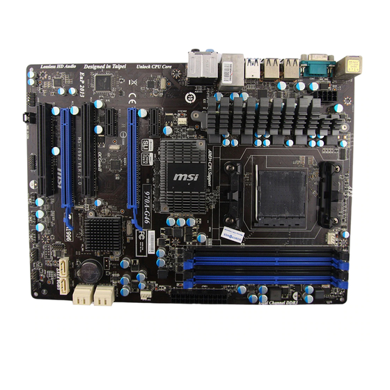
Unpacking
Thank you for buying the MSI
to make sure your motherboard box contains the following items. If something is
missing, contact your dealer as soon as possible.
Motherboard
I/O Shield
970A GAMING PRO CARBON
®
Drivers & Utilities
Disc
SATA Cable x2
motherboard. Check
Motherboard User
Guide
SLI Bridge
Connector
Unpacking
1
Advertisement
Table of Contents

Related Manuals for MSI 970A


Summary of Contents for MSI 970A
-
Page 1: Unpacking
Unpacking Thank you for buying the MSI 970A GAMING PRO CARBON motherboard. Check ® to make sure your motherboard box contains the following items. If something is missing, contact your dealer as soon as possible. Drivers & Utilities Motherboard User... -
Page 2: Safety Information
Safety Information The components included in this package are prone to damage from electrostatic discharge (ESD). Please adhere to the following instructions to ensure successful computer assembly. Ensure that all components are securely connected. Loose connections may cause the computer to not recognize a component or fail to start. Hold the motherboard by the edges to avoid touching sensitive components. -
Page 3: Quick Start
Quick Start Preparing Tools and Components AM3/ AM3+ CPU ® Thermal Paste CPU Fan DDR3 Memory Power Supply Unit Chassis SATA Hard Disk Drive Graphics Card SATA DVD Drive A Package of Screws Phillips Screwdriver Quick Start... -
Page 4: Installing A Processor
Installing a Processor Quick Start... -
Page 5: Installing Ddr3 Memory
Installing DDR3 memory Quick Start... -
Page 6: Connecting The Front Panel Header
Connecting the Front Panel Header HDD LED + Power LED + HDD LED - Power LED - Reset Switch Power Switch Reset Switch Power Switch JFP1 Reserved No Pin JFP1 HDD LED - HDD LED HDD LED + POWER LED - POWER LED POWER LED + Quick Start... -
Page 7: Installing The Motherboard
Installing the Motherboard Quick Start... -
Page 8: Installing Sata Drives
Installing SATA Drives Quick Start... -
Page 9: Installing A Graphics Card
Installing a Graphics Card Quick Start... -
Page 10: Connecting Peripheral Devices
Connecting Peripheral Devices Quick Start... -
Page 11: Connecting The Power Connectors
Connecting the Power Connectors ATX_PWR1 CPU_PWR1 Quick Start... -
Page 12: Power On
Power On Quick Start... -
Page 13: Table Of Contents
Contents Unpacking ......................1 Safety Information ....................2 Quick Start ......................3 Preparing Tools and Components ................3 Installing a Processor ..................... 4 Installing DDR3 memory ..................5 Connecting the Front Panel Header ............... 6 Installing the Motherboard ..................7 Installing SATA Drives..................... - Page 14 JBAT1: Clear CMOS (Reset BIOS) Jumper ............37 EZ Debug LED: Debug LED indicators ..............37 BIOS Setup ......................38 Entering BIOS Setup ..................... 38 Resetting BIOS ...................... 39 Updating BIOS ....................... 39 Overview ....................... 40 SETTINGS ......................41 Advanced ....................... 41 Boot ........................
-
Page 15: Specifications
Specifications Supports AMD / Phenom / Athlon II/ Sempron ® ™ ™ ™ ™ processors for Socket AM3/ AM3+ Chipset 970 & SB950 Chipset ® 4x DDR3 memory slots, support up to 32GB Memory Supports DDR3 1066/ 1333/ 1600/ 1866/ 2133(OC) MHz ƒ... - Page 16 Continued from previous page 1x PS/2 keyboard/ mouse combo port 8x USB 2.0 ports 1x USB 3.1 Gen2 Type-A port Back Panel 1x USB 3.1 Gen2 Type-C port Connectors 1x LAN (RJ45) port 1x optical S/PDIF OUT connector 6x audio jacks 1x 24-pin ATX main power connector 1x 8-pin ATX 12V power connector 6x SATA 6Gb/s connectors...
- Page 17 Continued from previous page Drivers COMMAND CENTER LIVE UPDATE 6 FAST BOOT SUPER CHARGER GAMING APP USB SPEED UP Software GAMING LAN MANAGER Nahimic 2 Open Broadcaster Software Norton™ Internet Security Solution Google Chrome™ ,Google Toolbar, Google Drive SteelSeries Engine 3 DRAGON EYE Continued on next page Specifications...
- Page 18 Continued from previous page AUDIO BOOST 3 Isolated Audio PCB ƒ EMI Shielding ƒ Dual Headphone Amplifiers ƒ High Quality Audio Capacitors ƒ Golden Audio Connectors ƒ GAME BOOST Easy Overclocking ƒ GAMING LAN Intel Gigabit Ethernet ® ƒ GAMING Network Manager power by cFos ƒ...
- Page 19 MILITARY CLASS 4 Military Class Component ƒ Military Class Stability and Reliability ƒ ESD Protection ˜ EMI Protection ˜ Humidity Protection ˜ MSI Exclusive Circuit Protection ˜ Features High Temperature Protection ˜ VGA Armor Slot ˜ COMMAND CENTER System Monitor ƒ...
-
Page 20: Block Diagram
Block Diagram 2 Channel DDR3 Memory x16/x8 Switch AMD RX980 PCI Express Bus PCI Express Bus ASMEDIA ASM1143 PCI Express Bus USB 3.1 Gen1 PCIe x1 slot Switch Intel PCIe x1 slot I211 PCIe x1 slot ALINK Switch PCI Express Bus ASMEDIA ASM1143 USB 3.1 Gen1... -
Page 21: Rear I/O Panel
Rear I/O Panel Audio Ports PS/2 USB 3.1 Optical S/PDIF-Out Gen2 USB 3.1 Gen2 Type-C USB 2.0 LAN Port LED Status Table Link/ Activity LED Speed LED Status Description Status Description No link 10 Mbps connection Yellow Linked Green 100 Mbps connection Blinking Data activity Orange... -
Page 22: Realtek Hd Audio Manager
Realtek HD Audio Manager After installing the Realtek HD Audio driver, the Realtek HD Audio Manager icon will appear in the system tray. Double click on the icon to launch. Device Selection Advanced Settings Jack Status Application Enhancement Main Volume Connector Strings Profiles... - Page 23 Audio jacks to headphone and microphone diagram Audio jacks to stereo speakers diagram AUDIO INPUT Audio jacks to 7.1-channel speakers diagram AUDIO INPUT Rear Front Side Center/ Subwoofer Rear I/O Panel...
-
Page 24: Overview Of Components
Overview of Components DIMMB2 CPU_FAN1 DIMMB1 CPU Socket CPU_PWR1 DIMMA2 SYS_FAN3 SYS_FAN1 DIMMA1 EZ Debug LED ATX_PWR1 JBAT1 PCI_E1 JUSB5 PCI_E2 SATA5_6 PCI_E3 SATA3_4 PCI_E4 SATA1_2 PCI_E5 SYS_FAN2 PCI1 M2_1 JAUD1 JFP2 JSP1 SYS_FAN4 JFP1 JCOM1 JCI1 JUSB3 JTPM1 JUSB2 JLED1 JUSB1 JUSB4... - Page 25 Component Contents Port Name Port Type Page CPU_FAN1, SYS_FAN1~4 Fan Connectors CPU_PWR1, ATX_PWR1 Power Connectors CPU Socket AM3/ AM3+ DIMMA1~2, DIMMB1~2 DIMM Slots EZ Debug LED Debug LED indicators JAUD1 Front Audio Connector JBAT1 Clear CMOS (Reset BIOS) Jumper JCI1 Chassis Intrusion Connector JCOM1 Serial Port Connector...
-
Page 26: Cpu Socket
Always unplug the power cord from the power outlet before installing or removing the CPU. Please retain the CPU protective cap after installing the processor. MSI will deal with Return Merchandise Authorization (RMA) requests if only the motherboard comes with the protective cap on the CPU socket. -
Page 27: Dimm Slots
DIMM Slots DIMMA1 DIMMB1 Channel A Channel B DIMMA2 DIMMB2 Memory module installation recommendation DIMMB1 DIMMB2 DIMMB1 DIMMA1 DIMMA1 DIMMA2 DIMMA1 Important Always insert memory modules in the DIMMA1 slot first. Due to chipset resource usage, the available capacity of memory will be a little less than the amount of installed. -
Page 28: Pci_E1~5, Pci1: Pcie/ Pci Expansion Slots
If you install a large and heavy graphics card, you need to use a tool such as MSI Gaming Series Graphics Card Bolster to support its weight and to prevent deformation of the slot. Overview of Components... -
Page 29: M2_1: M.2 Slot
M2_1: M.2 Slot Important Intel RST only supports PCIe M.2 SSD with UEFI ROM, ® does not support Legacy ROM. Installing M.2 module Remove the screw from the base screw. Remove the base screw. Tighten the base screw into the hole of the distance to the M.2 slot as the length your M.2 module. -
Page 30: Sata1~6: Sata 6Gb/S Connectors
SATA1~6: SATA 6Gb/s Connectors These connectors are SATA 6Gb/s interface ports. Each connector can connect to one SATA device. SATA6 SATA5 SATA4 SATA3 SATA2 SATA1 Important Please do not fold the SATA cable at a 90-degree angle. Data loss may result during transmission otherwise. -
Page 31: Cpu_Pwr1, Atx_Pwr1: Power Connectors
CPU_PWR1, ATX_PWR1: Power Connectors These connectors allow you to connect an ATX power supply. CPU_PWR1 Ground +12V Ground +12V Ground +12V Ground +12V +3.3V +3.3V +3.3V -12V Ground Ground PS-ON# Ground Ground Ground ATX_ PWR1 Ground Ground PWR OK 5VSB +12V +12V +3.3V... -
Page 32: Jusb4~5: Usb 3.1 Gen1 Connectors
JUSB4~5: USB 3.1 Gen1 Connectors These connectors allow you to connect USB 3.1 Gen1 ports on the front panel. JUSB5 JUSB4 Power USB2.0+ USB3_RX_DN USB2.0- USB3_RX_DP Ground Ground USB3_TX_C_DP USB3_TX_C_DN USB3_TX_C_DN USB3_TX_C_DP Ground Ground USB3_RX_DP USB2.0- USB3_RX_DN USB2.0+ Power Ground No Pin Important Note that the Power and Ground pins must be connected correctly to avoid possible... -
Page 33: Jusb1~3: Usb 2.0 Connectors
JUSB1~3: USB 2.0 Connectors These connectors allow you to connect USB 2.0 ports on the front panel. USB0- USB1- USB0+ USB1+ Ground Ground No Pin Important Note that the VCC and Ground pins must be connected correctly to avoid possible damage. -
Page 34: Cpu_Fan1, Sys_Fan1~4: Fan Connectors
CPU_FAN1, SYS_FAN1~4: Fan Connectors Fan connectors can be classified as PWM (Pulse Width Modulation) Mode and Voltage Mode. PWM Mode fan connectors provide constant 12V output and adjust fan speed with speed control signal. Voltage Mode fan connectors control fan speed by changing voltage. -
Page 35: Jaud1: Front Audio Connector
JAUD1: Front Audio Connector This connector allows you to connect audio jacks on the front panel. MIC L Ground MIC R Head Phone R MIC Detection SENSE_SEND No Pin Head Phone L Head Phone Detection JCI1: Chassis Intrusion Connector This connector allows you to connect the chassis intrusion switch cable. Normal Trigger the chassis intrusion event... -
Page 36: Jled1: Rgb Led Connector
JLED1: RGB LED connector This connector allows you to connect the RGB LED strip. +12V Important This connector supports 5050 RGB multi-color LED strips (12V/G/R/B) within 2 meters. Always turn off the power supply and unplug the power cord from the power outlet before installing or removing the RGB LED strip. -
Page 37: Jbat1: Clear Cmos (Reset Bios) Jumper
JBAT1: Clear CMOS (Reset BIOS) Jumper There is CMOS memory onboard that is external powered from a battery located on the motherboard to save system configuration data. If you want to clear the system configuration, set the jumpers to clear the CMOS memory. Keep Data Clear CMOS/ Reset BIOS... -
Page 38: Bios Setup
Press Delete key, when the Press DEL key to enter Setup Menu, F11 to enter Boot Menu message appears on the screen during the boot process. Use MSI FAST BOOT application. Click on GO2BIOS button and choose OK. The system will reboot and enter BIOS setup directly. -
Page 39: Resetting Bios
Updating BIOS Updating BIOS with M-FLASH Before updating: Please download the latest BIOS file that matches your motherboard model from MSI website. And then save the BIOS file into the USB flash drive. Updating BIOS: Press Del key to enter the BIOS Setup during POST. -
Page 40: Overview
Virtual OC Genie Button - enables or disables the OC Genie function by clicking on this button. When enabled, this button will be light. Enabling OC Genie function can automatically overclock with MSI optimized overclocking profile. Important We recommend that you do not to make any modification in OC menu mode and do not to load defaults after enabling the OC Genie function. -
Page 41: Settings
SETTINGS System Status System Date Sets the system date. Use tab key to switch between date elements. The format is <day> <month> <date> <year>. <day> Day of the week, from Sun to Sat, determined by BIOS. Read-only. <month> The month from Jan. through Dec. <date>... - Page 42 fPCI Latency Timer [32] Sets latency timer of PCI interface device. [Options: 32, 64, 96, 128, 160, 192, 224, 248 PCI Bus clocks] ACPI Settings Sets ACPI parameters of onboard power LED behaviors. Press Enter to enter the sub- menu. fACPI Standby State Specifies the power saving modes for ACPI function.
- Page 43 fSATA Mode [AHCI Mode] Sets the operation mode of the onboard SATA controller. [AHCI Mode] Specify the AHCI mode for SATA storage devices. AHCI (Advanced Host Controller Interface) offers some advanced features to enhance the speed and performance of SATA storage device, such as Native Command Queuing (NCQ) and hot-plugging.
- Page 44 Disables this function. fMSI Fast Boot [Disabled] MSI Fast Boot is the fastest way to boot the system. It will disable more devices to speed up system boot time which is faster than the boot time of Fast Boot. [Enabled] Enables the MSI Fast Boot function to speed up booting time.
- Page 45 Boot [Disabled] Enables or disables the fast boot feature for Windows 8/ 8.1. This item will only be available when MSI Fast Boot is disabled. [Enabled] Enables the Fast Boot configuration to accelerate system boot time. [Disabled] Disables the Fast Boot configuration.
-
Page 46: Boot
fResume From S3/S4/S5 by PS/2 Keyboard [Disabled] Enables or disables the system wake up by PS/2 keyboard. [Any Key] Enables the system to be awakened from S3/ S4/ S5 state when activity of any key on PS/2 keyboard is detected. [Hot Key] Enables the system to be awakened from S3/ S4/ S5 state when activity of hot key on PS/2 keyboard is detected. -
Page 47: Save & Exit
Important When selecting the Administrator / User Password items, a password box will appear on the screen. Type the password then press <Enter>. The password typed now will replace any previous set password from CMOS memory. You will be prompted to confirm the password. - Page 48 Important Overclocking your PC manually is only recommended for advanced users. Overclocking is not guaranteed, and if done improperly, it could void your warranty or severely damage your hardware. If you are unfamiliar with overclocking, we advise you to use OC Genie function for easy overclocking.
- Page 49 CPU Core Control [Auto] This item allows you to select the number of active processor cores. When set to Auto, the CPU will operate under the default number of cores. DRAM Frequency [Auto] Sets the DRAM frequency. Please note the overclocking behavior is not guaranteed. Adjusted DRAM Frequency Shows the adjusted DRAM frequency.
- Page 50 Enter OC and set Unlock CPU Core to Enabled. Set Adjust CPU-NB Ratio and HT Link Speed to [x8]. Save changes and exit the BIOS setup. System restart. Clear CMOS data. Fail Success You will see the X4 (quad core) or X2 (dual core for The CPU does not support CPU core Sempron series only) during POST.
- Page 51 CPU Specifications Press Enter to enter the sub-menu. This sub-menu displays the information of installed CPU. You can also access this information menu at any time by pressing F4. Read only. fCPU Technology Support Press Enter to enter the sub-menu. The sub-menu shows the key features of installed CPU.
-
Page 52: M-Flash
M-FLASH Important M-Flash function allows you to update BIOS from USB flash disk (FAT32/ NTFS format only). Save BIOS to storage Saves the current BIOS file to the USB flash disk. The USB flash disk drive should be in FAT32 format. Update BIOS Selects a BIOS file in the USB flash disk (NTFS/ FAT32 format) to update the BIOS. -
Page 53: Oc Profile
OC PROFILE Overclocking Profile 1/ 2/ 3/ 4/ 5/ 6 Overclocking Profile 1/ 2/ 3/ 4/ 5/ 6 management. Press Enter to enter the sub-menu. fSet Name for Overclocking Profile 1/ 2/ 3/ 4/ 5/ 6 Name the current overclocking profile. fSave Overclocking Profile 1/ 2/ 3/ 4/ 5/ 6 Save the current overclocking profile. -
Page 54: Hardware Monitor
HARDWARE MONITOR Temperature & Speed graphic display Temperature & Speed information control field Voltage display Temperature & Speed information Shows the current CPU temperature, system temperature and fans' speeds. Temperature & Speed graphic display The red graph shows the minimum and maximum temperatures that be set on the Fan control field. -
Page 55: Software Description
7/ 8.1/ 10. ® Installing Drivers Start up your computer in Windows 7/ 8.1/ 10. ® Insert MSI Driver Disc into your optical drive. ® The installer will automatically appear and it will find and list all necessary drivers. Click Install button. -
Page 56: Command Center
COMMAND CENTER COMMAND CENTER is an user-friendly software and exclusively developed by MSI, helping users to adjust system settings and monitor status under OS. With the help of COMMAND CENTER, making it possible to achieve easier and efficient monitoring process and adjustments than that under BIOS. In addition, the COMMAND CENTER can be a server for mobile remote control application. - Page 57 CPU Fan CPU Fan control panel provides Smart mode and Manual Mode. You can switch the control mode by clicking the Smart Mode and Manual Mode buttons on the top of the CPU Fan control panel. Manual Mode - allows you to manually control the CPU fan speed by percentage.
- Page 58 Option Buttons - Advanced When click the Advanced button, The Voltage, Fan and DRAM icons will appear. Voltage - allows you to adjust advanced voltage values of CPU and chipset. Fan - allows you to control the system fans speed. DRAM - shows the current Advanced DRAM parameters, and allows you to change the settings by selecting values from the drop-down menu on the right hand side.
- Page 59 Find the IP address on the SoftAP Management Setting area, and enter the IP address on your MSI COMMAND CENTER APP to link your system. ® Press Refresh on the MSI COMMAND CENTER APP to verify that monitoring and ® OC functions are working properly.
-
Page 60: Live Update 6
LIVE UPDATE 6 LIVE UPDATE 6 is an application for the MSI system to scan and download the latest ® drivers, BIOS and utilities. With LIVE UPDATE 6, you don’ t need to search the drivers on websites, and don’ t need to know the models of motherboard and graphics cards. -
Page 61: Total Installer
Choose Automatic scan, system will automatically scan all the items and search for the latest update files. Or you can choose Manual scan and select the items you wish to scan. Click the Scan button at the bottom. It may take several moments to complete the process. -
Page 62: Gaming App
Run MSI GAMING APP APP on your android device. ® Press the Remote Control Setting icon on the MSI GAMING APP APP to find the ® paired device Name you set on the Remote Control Setting panel. Enter the Password you set on the Remote Control Setting panel.0... - Page 63 LED Effect LED Effect allows you to control LED lights on your motherboard. All LED - controls all LEDs on your motherboard. Each LED - separately controls each segment of LEDs on your motherboard. MB Extend LED - controls the extended RGB LED strip. Please follows the steps to ƒ...
- Page 64 Eye Rest Eye Rest allows you to optimize the display on your monitor. EyeRest - reduces blue-light of your LED backlit screen, in order to protect your eyes. Gaming - automatically increase contrast ratio of your screen. Movie - automatically increase dynamic contrast ratio of your screen. Customize - allows you to adjust gamma, contrast and color balance for your screen.
- Page 65 Login Keys - provides hotkey login function. ƒ MSI Smart Keys - allows you to define hotkeys for MSI Smart Keys. ƒ Hotkey Manager - allows you to create, edit and delete hotkeys. Current Hotkeys - shows all existing hotkeys.
- Page 66 Mouse Master Mouse Master provides mouse macro function. You can also use it to change DPI of your mouse. DPI Setting Delay Time Default Button Macro Hot Key DPI Hot Key Mouse Action Action List Test Area Edit Buttons Clear Button Load Button Save Button Delay Time - allows you to input delay time and click the Add button to insert a...
-
Page 67: Usb Speed Up
USB SPEED UP Enabling USB SPEED UP can speed up the date transfer rates of the USB storage devices. Setting On/ Off button Display Setting - enables or disables Run USB SPEED UP when windows starts. Default setting is enabled On/ Off button - switches the USB SPEED UP on or off. -
Page 68: Gaming Lan Manager
GAMING LAN MANAGER GAMING LAN MANAGER is an utility for traffic shaping for the Windows 7/ 8.1/ 10. It can keep your internet fast during heavy upload/ download and improve your ping for online games. If your motherboard has a Wi-Fi module, GAMING LAN MANAGER provides virtual access point function for traffic shaping for your mobile devices. - Page 69 Speed Testing The speed testing is used to optimize bandwidth usage. To test the Upload and Down- load speed, please follow the steps below: Click the Network Test block in GAMING LAN MANAGER. Click Test Network Speed button. The test takes several minutes to test your network speed.
-
Page 70: Nahimic 2
HD Audio Recorder2 and Sound Tracker. Installation and Update Nahimic 2 is included in the audio driver. If you need to install it or update it, please use the Driver Disc with your motherboard or download the driver from MSI’ s official website. Audio Tab From this tab, you can access all of Nahimic 2’... - Page 71 Smart Loudness - maintains a constant volume for all elements of the audio ƒ experience to making them all sound softer, balanced or louder. Voice Clarity - boosts the speech in movies, video games and incoming ƒ communication from +0 through +12 dB (0 to 100%). Reset Button - restores the current profile to its default values.
- Page 72 Device properties - allows you to boost the volume and modify the left/ right ƒ balance of microphone. Clicks on this button and a device properties panel will show. Microphone Loopback - turns the microphone loopback On/Off. In order to avoid any feedback (Larsen effect).
- Page 73 Control Page - by clicking the arrow button, you can access the control page. Audio Launchpad ON/OFF - switches the Audio Launchpad on or off. ƒ HD Audio Recorder 2 - The HD Audio Recorder 2 is, by default, automatically ƒ...
-
Page 74: Steelseries Engine 3
SteelSeries Engine 3 SteelSeries Engine 3 is a unified platform built to support all of SteelSeries products. It can deploy your saved device settings automatically when switching between your favorite games or applications. After installation the SteelSeries Engine background processes will start and the interface will open automatically. - Page 75 Configuring Your Devices You can custom configurations for SteelSeries devices in their Configuration Windows. The top left displays the name of the configuration you are viewing, the body features widgets for customizing various functions of the device, and at the bottom are Save/ Revert buttons, a Live Preview toggle, and a button to open/close the collapsible Configuration List Panel.
-
Page 76: Dragon Eye
DRAGON EYE DRAGON EYE is an application allows you to watch a game guide, tutorial, live match or tournament stream while playing a game. In the game, you can use hotkeys to control / adjust the window of video. Size Settings Position Settings On / Off Switch Help... -
Page 77: Raid Configuration
RAID Configuration Below are the different types of a RAID. RAID 0 breaks the data into blocks which are written to separate hard drives. Spreading the hard drive I/O load across independent channels greatly improves I/O performance. RAID 1 provides data redundancy by mirroring data between the hard drives and provides enhanced read performance. - Page 78 View Drives Assignments This window displays the model number, capacities and assignment of the drives physically attached to the SATA host adapter. RAID Configuration...
- Page 79 LD View / LD Define Menu (Creating RAID) The selection of the RAID configuration should be based upon factors including performance, data security, and the number of drives available. It is best to carefully consider the long-term role of the system and plan the data storage strategy. RAID sets can be created either automatically, or to allow the greatest flexibility, manually.
- Page 80 On the Drives Assignments window, use the arrow key to choose the hard drives which you want to make part of the LD, use the space key to change the assignment to Y. Then press Ctrl + Y to save the configuration. A message will show, press Ctrl + Y to input a LD name as your desire or press any key to save default LD name.
- Page 81 The LD creation is done, the screen shows the LD information as below. Press ESC key to the main screen. Press ESC key to exit the utility, a message System is going to REBOOT! Are You Sure? will display, answer Y to exit it and the system will reboot. RAID Configuration...
- Page 82 Delete LD Menu (Deleting RAID) Press 3 on the main to enter the Delete LD Menu. Choose a LD No. you want to delete and press Del or Alt + D delete the RAID set. On the next screen, a message will display to inform you, press Ctrl + Y to delete the RAID set or other key to abort it.
-
Page 83: Installing Raid Driver
Please follow the instruction below to make an AMD RAID Driver for yourself. ® Insert the MSI Driver Disc into the optical drive. Click the Browse CD on the Setup screen. Copy all the contents in \\Chipset\WIN7\Packages\Drivers\SBDrv\SB9xx\RAID The driver diskette for AMD RAID Controller is done. -
Page 84: Installing Operating System On 2.2Tb Raid
Installing on 2.2TB RAID Operating System If you plan to install 64bit operating system on a RAID volume greater than 2.2TB, you can only manually create and load the RAID array in EFI shell. WARNING Create raid array will erase all the data stored on hard drives! Make sure to back up your files! There is no way to reverse the process! The following describes an example of how to install Windows 7/ 8 64bit on a RAID 0 volume greater than 2.2TB. - Page 85 Delete all logical drivers by selecting Logical Driver Main Menu > Logical Driver Delete Menu. + Logical Drive Main Menu + Logical Drive List Menu + Logical Drive Create Menu + Logical Drive Delete Menu Make sure there are not any logical drivers (as shown below). + Logical Drive Delete Menu - <Not Found Any Logical Drive>...
- Page 86 Back to Logical Driver Main Menu and fill Ld Name. + Logical Drive Create Menu + Usable Physical Drive List + Basic Setting - Raid Mode <RAID 0> - Stripe Block (KB) <64> - Initialization <Fast> - Gigabyte Boundary <Enable> - Read Policy <Read Ahead>...
- Page 87 USB 2.0 port (not USB 3.0 port) and click Browse. Important You can find the AMD RAID driver from MSI Driver Disc. The path is \\Chipset\WIN7\Packages\Drivers\SBDrv\SB9xx\RAID Please copy all the files in the folder to a USB flash drive.
- Page 88 Select Removable Disk from Browse for Folder dialog then click OK. Install AMD AHCI Compatible RAID Controller. Windows 7/ 8 64bit can find the RAID volume now. Please continue the installing procedure. RAID Configuration...
-
Page 89: Troubleshooting
Troubleshooting Lost BIOS password Before sending the motherboard for RMA repair, try to go over troubleshooting Clear the CMOS, but that will cause guide first to see if your got similar you to lose all customized settings in symptoms as mentioned below. the BIOS. -
Page 90: Regulatory Notices
MSI will comply with the product take back requirements at the end of life of MSI-branded products that are sold into the EU. You can return these products to local collection points.