
Related Manuals for DeLonghi DTR 906-IND


Summary of Contents for DeLonghi DTR 906-IND
- Page 1 DE ’ L O N G H I C OO KING US E R & I NSTA LL AT IO N I NSTRUCTIO NS D TR 906 - I N D F R E ES TA NDIN G EL E CT RI C DOUBLE OVEN W I T H I N D UCT IO N HO TP LATE...
-
Page 2: Table Of Contents
CONTENTS Page Number Introduction ..................Important Safeguards & Recommendations ........4 - 9 Cooking Hob ..................Control Panel ..................Use of induction hob ................12 - 20 Multifunction main oven (left oven) ............21 - 26 Conventional oven (right oven) ............27 - 29 Cooking guide .................. -
Page 3: Introduction
Dear Customer, Thank you for purchasing the DeLonghi DTR 906-IND freestanding electric double oven with induction hotplate. The safety precautions and recommendations listed below are for your own safety and that of others. They will also provide a means by which to make full use of the features offered by your appliance. -
Page 4: Important Safeguards & Recommendations
IMPORTANT SAFETY PRECAUTIONS AND RECOMMENDATIONS IMPORTANT: This appliance is designed and manufactured solely for the cooking of domestic (household) food and is not suitable for any non domestic application and therefore should not be used in a commercial environment. The appliance guarantee will be void if the appliance is used within a non domestic environment i.e. - Page 5 • Do not attempt to modify the technical characteristics of the appliance as this may become dangerous to use. The manufacturer declines all responsibility for any inconvenience resulting from the inobservance of this condition. • Do not operate your appliance by means of an external timer or separate remote-control system.
- Page 6 • The manufacturer declines all liability for injury to persons or damage to property caused by incorrect or improper use of the appliance. • WARNING: During use the appliance and its accessible parts become hot; they remain hot for some time after use. Care should be taken to avoid touching heating elements (on –...
- Page 7 Switch on the empty oven on max to eliminate grease from the – heating elements. Disconnect the appliance from the electrical power supply, let – the oven cool down and clean the interior of the oven with a cloth soaked in water and neutral detergent; then dry carefully. •...
- Page 8 • If the power supply cable is damaged, it must be replaced only by an authorized service agent in order to avoid a hazard. • INDUCTION HOBS: Metallic objects such as knives, forks, spoons and lids should – not be placed on the hob surface since they can get hot. Do not use metallic kitchen utensils (e.g.
- Page 9 ENERGY LABELLING/ECODESIGN • Commission delegated regulation (EU) No 65/2014 (supplementing Directive 2010/30/EU of the European Parliament and of the Council). • Commission regulation (EU) No 66/2014 (implementing Directive 2009/125/EC of the European Parliament and of the Council). Reference to the measurement and calculation methods used to establish compliance with the above requirements: •...
-
Page 10: Cooking Hob
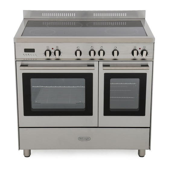
1 - COOKING HOB Fig. 1.1 INDUCTION INDUCTION COOKING HOB 1. Induction cooking zone Ø 200 mm Normal Power: 2300 W Booster Power: 3000 W 2. Induction cooking zone Ø 160 mm Normal Power: 1400 W 3. Cooking zones display Note: The Nominal and Booster Power may change depending on the size and material of the pan set on the cooking zone. -
Page 11: Control Panel
2 - CONTROL PANEL Fig. 2.1 CONTROL PANEL - Controls description Front right cooking zone control knob Rear right cooking zone control knob Rear left cooking zone control knob Front left cooking zone control knob Multifunction oven switch knob (left oven) Multifunction oven thermostat knob (left oven) Conventional oven thermostat knob (right oven) Conventional oven switch knob (right oven) -
Page 12: Use Of Induction Hob
3 - USE OF INDUCTION HOB The ceramic hob is fitted with induction cooking zones. These zones, shown by painted disks on the ceramic surface, are controlled by separate knobs positioned on the control panel. In the front central area of the hob, the cooking zones display (composed by no. - Page 13 REMAINING HEAT INDICATORS When the temperature of a cooking zone is still hot, the relevant remaining heat indicator lights up on the display to alert you of the hot surface. Avoid touching the hob surface over the cooking area. Please pay special attention to children.
- Page 14 CONTROL KNOBS Each cooking zone is adjusted by a separate control knob positioned on the control panel and the operation is controlled by the electronic system. If a cooking zone is not turned Off the electronic system automatically switches it Off after a pre-set time which depends on the power setting.
- Page 15 1 - 9 POWER LEVEL Turn the knob clockwise to set the desired power level between 1 (minimum) and 9 (maximum). The power level can be modified at any time by turning the knob clockwise or anti-clockwise to a different setting. The cooking zone display shows the selected level.
- Page 16 “FAST HEATING” FUNCTION Turn the control knob anti-clockwise to the “A” setting and then release the knob (after the “beep”); the relative symbol lights up on the cooking zone display. Within 5 seconds turn the knob to the desired power level (between 1 and 9); once a setting has been selected, and the chosen power level will flash in alternation on the control panel display.
- Page 17 MAXIMUM USABLE POWER COOKING ZONES The right and left cooking zones are controlled by two Controlled by separate power boards and the maximum total power 1st power board per each power board is 3700 W. Should the cooking zones of one power board require more than 3700 W, the last selected power level has priority and the power of the other cooking zone is automatically reduced to the remaining power available.
- Page 18 ERROR CODES ON THE COOKING ZONES DISPLAY Error code Example What to do Switch off the cooker and disconnect it from the mains. Erxx Wait for about 1 minute, then reconnect or Ex (not E2 or the cooker and turn on the cooking zones. Wait for about 1 minute and if the error message does not appear again the cooking zones can be used.
- Page 19 ADVICE FOR SAFE USE OF THE • Before switching on make sure that you have the correct knob for the hotplate chosen. It is advisable to put the pan on the hotplate before switching on and to take it away after switching off.
- Page 20 CLEANING • Before you begin cleaning make sure that the appliance is switched off. • Remove any encrustation using the scraper provided. • Dust or food particles can be removed with a damp cloth. • If you use a detergent, please make sure that it is not abrasive or scouring. Abrasive or scouring powders can damage the glass surface of the hob.
-
Page 21: Multifunction Main Oven (Left Oven)
4 - MULTIFUNCTION ELECTRIC MAIN OVEN OPERATING PRINCIPLES Attention: The oven door becomes Heating cooking very hot during operation. MULTIFUNCTION oven are obtained in the Keep children away. following ways: by normal convection GENERAL FEATURES The heat is produced by the upper and As its name indicates, this is an oven lower heating elements. - Page 22 Fig. 4.1 Fig. 4.2 (fig. 4.1) TEMPERATURE KNOB To turn on the heating elements of the oven, set first the function selector to the required setting and then the thermostat knob to the desired temperature. To set the temperature, line up the temperature knob indicator with the required temperature.
- Page 23 GRILLING The infra-red heating element is switched on. The heat is diffused by radiation. Use with the oven door closed and the thermostat knob to between 50°C and 225°C . Preheat the oven for about 5 minutes. Introduce the food to be cooked, positioning the rack as close to the grill as possible. The dripping pan should be placed under the rack to catch the cooking juices and fats.
- Page 24 SLOW HEATING AND KEEPING FOOD WARM The upper element and the circular element connected in series, are switched on; also the fan is on. The heat is diffused by forced convection with the most heat being produced by the upper element. The temperature must be regulated between 50°C and 140°C with the thermostat knob.
- Page 25 SIMULTANEOUS COOKING OF DIFFERENT FOODS The MULTI-FUNCTION oven set on position gives simultaneous heterogeneous cooking of different foods. Different foods such as fish, cake and meat can be cooked together without mixing the smells and flavours. This is possible since the fats and vapors are oxidized while passing through the electrical element and therefore are not deposited onto the foods.
- Page 26 OVEN COOKING COOKING EXAMPLES Before introducing the food, preheat the T e m p e r a t u r e s a n d t i m e s a r e oven to the desired temperature. approximate as they vary depending on For a correct preheating operation, it is the quality and amount of food.
-
Page 27: Conventional Oven (Right Oven)
5 - CONVENTIONAL SMALL OVEN OPERATING PRINCIPLES Attention: the oven door becomes very hot during operation. Heating cooking CONVENTIONAL oven are obtained in the Keep children away. following ways: by normal convection The heat is produced by the upper and lower heating elements. - Page 28 Fig. 5.2 Fig. 5.1 (fig. 5.1) FUNCTION SELECTOR KNOB Rotate the knob clockwise to set the oven for one of the following functions: (fig. 5.2) TEMPERATURE KNOB To turn on the heating elements of the oven, set first the function selector to the required setting and then the thermostat knob to the desired temperature.
- Page 29 GRILLING The infra-red heating element is switched on. The heat is diffused by radiation. Use with the oven door closed and the thermostat knob to between 50°C and 225°C. Preheat the oven for about 5 minutes. Introduce the food to be cooked, positioning the rack as close to the grill as possible. The dripping pan should be placed under the rack to catch the cooking juices and fats.
-
Page 30: Cooking Guide
6 - OVEN TEMPERATURE GUIDE Electric oven temperature Cooking process Oven heat Gas mark °C °F Keeping food hot, very cool ½ milk puddings Egg custards cool Rich fruit cakes, cool braising Low temperature moderate roasting, shortbread Victoria sandwich, plain fruit cake, moderate baked fish Small cakes, choux... -
Page 31: Clock And Timer With "Touch-Control" Keys
7 - ELECTRONIC PROGRAMMER The electronic programmer is a device which groups together the following functions: • 24 hours clock with illuminated display • Timer (up to 23 hours and 59 minutes) • Program for automatic oven cooking • Program for semi-automatic oven cooking Description of the buttons: Description illuminated... - Page 32 (fig. 7.2) ELECTRONIC CLOCK ELECTRONIC TIMER The programmer is equipped with an The timer program consists only of a electronic clock with illuminated numbers buzzer which may be set for a maximum which indicates hours and minutes. period of 23 hours and 59 minutes. If the AUTO symbol is flashing push the Upon immediate connection of the oven or after a power cut, three zeros will flash on...
- Page 33 AUTOMATIC OVEN COOKING Set the temperature and the cooking program by using the switch and To cook food automatically in the oven, it is thermostat knobs of the oven (see necessary to: specific chapters). Set the length of the cooking period. oven programmed Set the end of the cooking time.
- Page 34 SEMI-AUTOMATIC COOKING At the end of the cooking time the oven will turn off automatically, the symbol This is used to automatically switch off the will turn off, AUTO will flash and a buzzer oven after the desired cooking time has will be sound, which can be turned off by elapsed.
- Page 35 IMPORTANT – OVEN NOT WORKING If the oven is not working, it may have been accidently set to “AUTOMATIC” or the power to the appliance was interrupted. If the Timer is showing the letter “AUTO” as below or the time of day is flashing, the Oven may not turn on or be delayed in its operation. Before requesting a service call, please refer to the timer set up instructions in this handbook and ensure the timer is set to “MANUAL”...
-
Page 36: Cleaning & Maintenance
8 - CLEANING AND MAINTENANCE GENERAL ADVICE However special care should be taken around the rear or the underneath of • Before you begin cleaning, you the appliance as these areas are not must ensure that the appliance is designed or intended to be touched and switched off at the cooker switch. - Page 37 • Inside of oven: The oven should always be cleaned after use when it has cooled down. The cavity should be cleaned using a mild detergent solution and warm water. Suitable proprietary chemical cleaners may be used only on enamel after first consulting the instructions supplied with the oven cleaner and testing a small sample on the oven cavity.
- Page 38 STORAGE COMPARTMENT The storage compartment is accessible through the pivoting panel (fig. 8.3). Do not store flammable material in the oven or in the drawer. Fig. 8.3 REPLACING THE OVEN LAMP WARNING: Ensure the appliance is switched off and disconnected from the electrical power supply before replacing the lamp to avoid the possibility of electric shock.
- Page 39 REMOVING THE OVEN DOORS The oven door can easily be removed as follows: Open the door to the full extent (fig. • 8.5a). • Open the lever “A” completely on the left and right hinges (fig. 8.5b). Hold the door as shown in fig. 8.9d. •...
- Page 40 REFIT THE DOORS Hold the door firmly (fig. 8.6a). Insert the hinge tongues into the slots, making sure that the groove drops into place as shown in the figure 8.6b. Open the door to its full extent. Fully close the levers “A” on the left and right hinges, as shown in the figure 8.6c.
- Page 41 CLEANING THE PANES OF GLASS The oven doors are fitted with no.2 panes: • no. 1 outside; • no. 1 inner. To clean the panes on both sides it is necessary to remove the inner pane as follows. REMOVING THE INNER PANE OF GLASS Fig.
- Page 42 AFTER CLEANING, REPLACE THE INNER GLASS PANE When replacing the inner glass pane, make sure that: • You replace the pane correctly, as shown. The pane must be in the position described below in order to fit into the door and to ensure that the Fig.
-
Page 43: Advice For The Installer
Advice for the installer IMPORTANT • The appliance is designed and approved for domestic use only and should not be installed in a commercial, semi commercial or communal environment. Your product will not be guaranteed if installed in any of the above environments and could affect any third party or public liability insurances you may have. -
Page 44: Installation
9 - INSTALLATION INSTALLATION This cookers has class “2/1” overheating protection so that it can be installed in a cabinet. The appliance must be kept no less than 200 mm away from any side wall which exceed the height of the hob surface (fig. 9.1). The furniture walls adjacent to the cooker must be made of material resistant to heat. - Page 45 FITTING THE ADJUSTABLE FEET The adjustable feet must be fitted to the base of the cooker before use (fig. 9.2). Rest the rear of the cooker on a piece of the polystyrene packaging exposing the base for the fitting of the feet. Fit the 4 legs by screwing them tight into the support base as shown in figure 8.3a.
- Page 46 MOVING THE COOKER WARNING: When raising cooker to upright position always ensure two people carry out this manoeuvre to prevent damage to the adjustable feet (fig. 9.5). Fig. 9.5 WARNING WARNING When moving cooker to its final position Be carefull: DO NOT LIFT the cooker by DO NOT DRAG (fig.
- Page 47 ANTI-TILT BRACKET Warning: This appliance must be restrained to prevent accidental tipping by fitting a bracket to the rear of the appliance and securely fixing it to the wall. To fit the anti-tilt bracket: After you have located where the cooker is to be positioned, mark on the wall the place where the 2 screws of the anti-tilt bracket have to be fitted.
-
Page 48: Electrical Installation
10 - ELECTRICAL INSTALLATION N.B. For connection to the mains, do not use adapters, reducers or IMPORTANT: The cooker must be branching devices as they can cause installed in accordance with the overheating and burning. manufacturer’s instructions. Incorrect installation, for which If the installation requires alterations to the t h e m a n u f a c t u r e r... - Page 49 CONNECTING THE FEEDER CABLE POWER SUPPLY 230 V ac 11100 W WARNING: If the power supply cable is damaged, it must be replaced only by an authorised service agent in order to FEEDER CABLE SECTION avoid a hazard. “TYPE H05RR-F” To connect the feeder cable to the cooker 230 V ac 3 x 6 mm...
- Page 50 230 V~ 230 V ac N (L2) 1 2 3 4 5 230 V~ N (L 400 V 3N~ 400 V 3N ac 1 2 3 4 5 400 V 3N~ 400 V 2N~ 400 V 2N ac 1 2 3 4 5 400 V 2N~ Fig.
-
Page 51: Guarantee & After Sales Service
11 - GUARANTEE Your new “De’Longhi” product comes with 12-month guarantee covering all parts and labour. If your appliance proves to be defective as a result of faulty materials or workmanship during the guarantee period, these parts will be repaired or replaced free of charge. AFTER SALES SERVICE Should you require service, spares or product information and advice: •... - Page 52 Descri pt i ons an d ill ustrati ons in this booklet a re giv en as simpl y ind icat ive. T h e ma nuf a ct ur er r es erv es the right, consider ing t he cha ract eri stics o f t he models described here, at any time and without notice, to make eventual necessary mo d ifi cat i on s f or the ir constr ucti on or for com merc ial n eeds.