Keating Of Chicago Miraclean Service & Preventative Maintenance Training
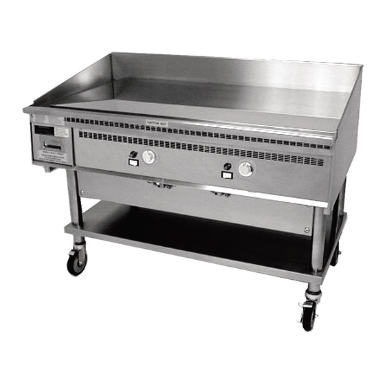
Gas griddle & top-side cooking head
Hide thumbs
Also See for Miraclean:
- Operator's training manual (27 pages) ,
- Service manual (21 pages) ,
- Specifications (2 pages)
Table of Contents
Advertisement
Quick Links
Advertisement
Table of Contents

Related Manuals for Keating Of Chicago Miraclean


Summary of Contents for Keating Of Chicago Miraclean
-
Page 2: Table Of Contents
Table of Contents ® MIRACLEAN GRIDDLE Customer Service ..........................1 Keating of Chicago Web Site .......................4 Miraclean Griddle Features ......................7 Calibration ............................8 Inspection ............................9 Installation ..........................10 - 12 Leveling ............................ 10 Gas Pressure .......................... 11 Quick Disconnect ........................12 Lighting ............................13 Lighting Problems ........................ -
Page 3: Customer Service
Customer Service For warranty problems on our equipment, have the end-user call 1-800-KEATING with model and serial #. - Page 4 Customer Service Our Customer Service Team can help you with everything from troubleshooting to parts identifi cation. must have the model and serial number of the unit when calling for assistance.
- Page 5 Customer Service Our policy at Keating is to provide you with a written quotation on any parts identifi ed. We want to ensure you receive the correct parts.
-
Page 6: Keating Of Chicago Web Site
Keating of Chicago Online Finding support for our products is easier than ever! You can visit our web site 24 hours a day at: keatingofchicago.com... - Page 7 Keating of Chicago Online From our Home page, you can easily fi nd: • Warranty Service contact information • Authorized Service Providers Directory • Download product manuals, updated service instructions, MSDS Sheets for Keating Klenzer, Acidox and Sea Powder products, and much more!
- Page 8 MIRACLEAN ® Griddles...
-
Page 9: Miraclean Griddle Features
MIRACLEAN ® Griddle Features ® Surface • MIRACLEAN ® – MIRACLEAN plating applied in an 8 step process yielding a surface as hard as a diamond – ¾" Plate • Hundreds of size combinations available • Gas and Electric Models •... -
Page 10: Calibration
No Calibration Required • Equipment Testing – All equipment tested at factory before shipping. – Thermostat has been calibrated at our factory. – Test Charts included in accessory box with manual. -
Page 11: Inspection
Equipment Inspection • Equipment is Inspected Prior to Shipping... -
Page 12: Installation
Installation • Leveling – Place a level on the griddle plate from side to side. For griddles on legs, the bottom foot is adjustable. Turn counter clockwise to decrease height, clockwise to increase height. Casters are adjustable by loosening the jam nut. When desired level is reached, tighten the jam nut. -
Page 13: Gas Pressure
Installation • Gas Pressure – Have installer follow gas pressure requirements. Installer should check incoming gas pressure and manifold pressure with all equipment in the kitchen on and operating. • Natural Gas 7" Supply 4" Manifold • LP Gas 11" Supply 10"... -
Page 14: Quick Disconnect
Installation • Quick Disconnect This griddle installation is correct. This griddle installation is incorrect – the quick disconnect should connect directly to the griddle. -
Page 15: Lighting
Lighting the MIRACLEAN ® Griddle • Make sure main gas valve is in “ON” position. • Make sure fl exible connector is connected. NOTE: Air in the supply line may require a longer than normal period of time to light griddle during initial installation,... - Page 16 Lighting the MIRACLEAN ® Griddle • Turn pilot gas valve knob to “PILOT” position. NOTE: We recommend lighting the burner on the side farthest from the incoming gas fi rst (left side when facing griddle). When the farthest burner receives gas, gas is available for...
- Page 17 Lighting the MIRACLEAN ® Griddle • Push in and hold the pilot gas valve knob, and while holding, push the red spark ignition button to light the pilot. (When griddle is fi rst installed, it may take longer than 90 seconds to...
- Page 18 Lighting the MIRACLEAN ® Griddle • When the spark ignites the pilot, continue to hold in for 60 seconds. Then release the pilot gas valve knob; the pilot should remain burning. Turn the knob to the “ON” position.
- Page 19 Lighting the MIRACLEAN ® Griddle • Turn On/Off switch to “ON” position. • Set thermostat knob to desired temperature. NOTE: The operating temperature should be from 10°F to 25°F lower than conventional griddles - we recommend 350°F.
-
Page 20: Lighting Problems
Lighting Problems Trouble Shooting PROBLEM: None of the pilots will light • No Gas – Check incoming gas line & quick disconnect in rear of griddle. • Note: Each section of the griddle is independent. – Air in gas line, (start-ups & reconnections) - Page 21 Lighting Problems Trouble Shooting PROBLEM: One of the pilots won’t light • #1 - Check Piezo – Verify spark is present (does pilot light using a match/lighter?) • Bend the electrodes into the correct position • #2 - Check Gas Valve Knob –...
- Page 22 Lighting Problems Trouble Shooting The millivolt valve is a thermopile self-powered combination gas control. Before checking the millivolt system, the following operations should be performed and observations made: 1. A genuine Keating millivolt thermostat should be used for millivolt operation. 2.
- Page 23 Lighting Problems Trouble Shooting PROBLEM: Pilot lights, but will not stay lit • #1 - Check millivolt output with Voltmeter or Multi-meter – With thermostat contacts open, 325 to 700 mV. – With thermostat contacts closed, 200 mV or more. –...
- Page 24 Lighting Problems Trouble Shooting NOTE: The millivolt system and individual components may be checked with a Millivolt meter having a 1-1000 mV range. Conduct each check below by connecting meter test leads to terminals as indicated. All readings are closed circuit.
- Page 25 Lighting Problems Trouble Shooting PROBLEM: Pilot lights, but will not stay lit • #2 - Check wire connection at gas valve magnet – Remove, recrimp if necessary – Check the black wire between TH terminal on gas valve and the thermostat. It must not have any breaks or bare spots that allow it to ground out.
- Page 26 Lighting Problems Trouble Shooting PROBLEM: Pilot lights, burner does not • #1 - Check for – Gas valve in pilot position. – Power switch or thermostat “OFF” position. – Loose wire connections.
- Page 27 Lighting Problems Trouble Shooting PROBLEM: Pilot lights, burner does not • #2 - Defective thermostat – With all components in “ON” position, clip a jumper wire between the terminals on the thermostat. If the burner ignites, replace the thermostat. • #3 - Defective switch –...
- Page 28 Lighting Problems Trouble Shooting PROBLEM: Pilot lights, burner does not • #4 - Defective gas valve – With a quality multi-meter, there are 3 sets of ohm checks to determine if there is high resistance in the gas valve. Note: when checking the ohm readings, the thermopile wire must be disconnected from the TP...
- Page 29 Lighting Problems Trouble Shooting PROBLEM: Pilot lights, burner does not • #4 - Defective gas valve, continued – With a quality multi-meter, there are 3 sets of ohm checks to determine if there is high resistance in the gas valve. Check 2: Place one point of the multi-meter on the THTP terminal on the valve...
- Page 30 Lighting Problems Trouble Shooting • Gas Valve Replacement Remove screws Surround 1. Remove screws from control panel. 2. Remove grease drawer, set to side. 3. Remove screws that hold surround. 4. Carefully guide control panel through surround. 5. Set heat shield off to side. 6.
- Page 31 Lighting Problems Trouble Shooting • Gas Valve Replacement , continued Remove nut bolts 7. Remove (2) nut bolts that attach griddle frame. 8. Griddles with grease chute on side of plate, go on to step 10. Griddles with grease chute in front of plate – disconnect the burner that sits over grease drawer.
- Page 32 Lighting Problems Trouble Shooting • Gas Valve Replacement , continued Wire ties Orifice Holder 9. A. Cut the wire ties that hold the burner to frame (there are 3 wires to cut). B. Lift the back of the burner so the stub on the bottom of the burner comes out of the hole in the frame.
- Page 33 Lighting Problems Trouble Shooting • Gas Valve Replacement , continued 11. Disconnect the wires attached Fitting to the gas valve. Pipe 12. Loosen nut. 13. Disconnect pilot tube. Pilot Tube 14. Unscrew gas valve to remove from gas pipe. 15. Remove fitting from old gas valve and clean it. Add new gas pipe sealant to threads, and install on new gas valve.
- Page 34 Lighting Problems Trouble Shooting • Gas Valve Replacement , continued 20. Slide frame back into cabinet and install the nuts and bolts. 21. Griddles with grease chute located on side of plate, go to step 22. Griddles with grease chute in front of plate – you will need to reinstall burner onto the frame.
-
Page 35: Heating Problems
Heating Problems Trouble Shooting PROBLEM: Improper Heating • #1 - Check for draft blowing on plate using a butane lighter. Observe fl ame. • #2 - Check for fl ue blockage. • #3 - Improper food loading (refer to chart). - Page 36 Heating Problems Trouble Shooting PROBLEM: Improper Heating • #4 - Take temperatures 12" back from front of plate over the inverted “V” using a surface thermometer (do not use an infrared thermometer).
- Page 37 Heating Problems Trouble Shooting PROBLEM: Improper Heating • #5 - Verify proper installation of the thermostat. Tip of bulb sticks out 1" past end of “V” channel.
-
Page 38: Cleaning
Cleaning the MIRACLEAN ® Griddle STEP 1 ® Scrape the Miraclean surface using the Keating scraper. DO NOT use bricks, stones, screens or chemicals to clean the griddle surface. DO NOT hack, chop, cut or hit the griddle surface. - Page 39 Cleaning the MIRACLEAN ® Griddle STEP 2 ® Clean your Miraclean Griddle while warm at approximately 300°F. Use entire pitcher of water - pour ½ pitcher at a time on the surface while brushing with the Keating Palmetto brush. Scrub the...
- Page 40 Cleaning the MIRACLEAN ® Griddle STEP 3 Once the griddle has been cleaned, sprinkle Keating Klenzer on the surface. Add water, and using the Palmetto brush, work the Klenzer and water into a paste. Allow to dry, and then polish with a soft cloth.
-
Page 41: Top-Side Cooker
™ Top-Side Cooker Keating recommends setting the temperature of the Top-Side Cooker 50°F higher than the surface of the MIRACLEAN griddle – 350°F for the griddle, 400°F for the Top-Side. -
Page 42: Features
™ Top-Side Cooker Features • Cuts cooking time in half • Micro-Leveler • Miraclean ® Plate • Manual or Automatic design • Polymer coated reversible cooking sheets for easy clean-up... - Page 43 ™ Top-Side Cooker Features...
-
Page 44: Control Box
™ Top-Side Control Box Location Top-Side control box(es) should be located in a well ventilated area. The maximum ambient temperature for each control box is 122°F (50°C). - Page 45 ™ Top-Side Control Box Location The Top-Side control boxes shown are stacked and contained in a box causing high ambient temperatures - control boxes should always be located in a well ventilated area.
-
Page 46: Setting The Temperature
™ Setting the Temperature of the Top-Side • Turn the ON/OFF switch to the “ON” position. - Page 47 ™ Setting the Temperature of the Top-Side • To set the temperature, press and hold the “PUSH TO SET” button on the thermostat and adjust the knob to the desired temperature. To increase the temperature, turn clockwise. To decrease, turn the knob counterclockwise.
-
Page 48: Digital Timers
Checking the Digital Timers Operating Logic When the timer is powered up, the display will show the time setting for the channel that was operated last and the relay output contacts will be open. To start a cycle, press the desired channel button (1-3). - Page 49 Setting the Digital Timers • Standard feature with Auto-Lift Programming Each timer may be set for a total of 3 times. To program the timer, it must be in the idle mode. Press and hold the set button for approximately two seconds. The display will show “SET”.
- Page 50 Pause the Digital Timers Pause Feature To pause a cycle in progress, press any button. The relay output contacts will open, the display will flash, and the countdown will pause. To resume the countdown, press any button. The display will resume the normal countdown and the relay output contacts will close.
- Page 51 Canceling the Digital Timers Canceling a Cycle To cancel a cycle in progress press and hold any button for approximately two seconds. The relay output contacts will open and the display will show the time setting for the channel last used.
-
Page 52: Trouble Shooting
Cooking Head Trouble Shooting PROBLEM: Uneven heating • Check the micro leveler – are both plungers in the same position? - Page 53 Cooking Head Trouble Shooting PROBLEM: Improper heating • Check temperature probes (high limit & thermostat). High Limit – Probe @ room temperature: 1,000 -1,100 ohms @ 400°F: 1,800 ohms Thermostat – Disconnect probe from controller and measure resistance. If resistance is over 15%, replace probe.
-
Page 54: Auto-Lift
Auto-Lift Trouble Shooting • Auto–Lift • Uses a timer to raise and lower actuator PROBLEM: Head fails to lift or lower – Verify proper timer operation. – Check circuit breaker in rear. – Verify voltage to actuator (replace actuator if necessary). -
Page 55: Cleaning
Cleaning the Cooking Sheet End of Day Cleaning 1. Remove the cooking sheet from the cooking head. 2. Wash the cooking sheet in a sink with soap and water and dry thoroughly. 3. After the cleaning is complete, reverse the cooking sheet and reattach it to the cooking head. - Page 56 Cleaning the Cooking Head 1. With the cooking sheet removed, scrape Miraclean surface from front to back with Keating griddle scraper. 2. Clean and polish surface with Keating Klenzer on a damp soft cotton cloth. Wipe off excess Klenzer.
-
Page 57: Warranty
Warranty... - Page 58 Warranty Our equipment has a standard one year parts and labor warranty. NOTE: All calls on equipment which may be within the warranty time frame are not necessarily warranty calls. A responsible and experienced servicer knows the difference between a legitimate warranty repair and operator generated failure.
- Page 59 Warranty • Work Authorization Form...
- Page 60 Warranty Our labor guide includes labor rates, and goes into greater detail regarding warranty invoices and our part return process.
-
Page 61: Returned Parts
Returned Parts • If the Return Authorization is not included with your replacement part, you must call 1-800-KEATING for an Authorized Merchandise Return. • All parts returned from the field are tested. • “New” parts tested for proper operation before returning to stock. - Page 62 Returned Parts • Warranty Part Test Report Form...
- Page 63 Sample Rejected Part EXAMPLE: Rejected Thermostat – The manufacturer of the thermostat voids the warranty if the set screw in the stem of the thermostat has been adjusted. Keating will not pay for warranty service to adjust the set screw.