
Related Manuals for NETGEAR M4500 Series


Summary of Contents for NETGEAR M4500 Series
- Page 1 M4500 Intelligent Fully Managed Switches Model M4500-32C Model M4500-48XF8C NETGEAR, Inc. September 2019 350 E. Plumeria Drive 202-12040-02 San Jose, CA 95134, USA...
-
Page 2: Revision History
Do not use this device outdoors. If you connect cables or devices that are outdoors to this device, see http://kb.netgear.com/000057103 for safety and warranty information. Trademarks © NETGEAR, Inc., NETGEAR, and the NETGEAR Logo are trademarks of NETGEAR, Inc. Any non-NETGEAR trademarks are used for reference purposes only. Revision History Publication Part Publish Date... -
Page 3: Safety Instructions And Warnings
Any device that is located outdoors and connected to this product must be properly grounded and surge protected. Failure to follow these guidelines can result in damage to your NETGEAR product, which might not be covered by NETGEAR’s warranty, to the extent permissible by applicable law. - Page 4 Depending on your device, use only a supplied power adapter or approved power cable: If your device uses a power adapter: If you were not provided with a power adapter, contact your local NETGEAR reseller. The power adapter must be rated for the product and for the voltage and current ...
-
Page 5: Table Of Contents
Troubleshooting ....................31 Diagnostic Switch Indicator ................31 Power and Cooling Problems ................31 Installation ....................31 In-Band Access ....................32 Replacing the Power Supply ................32 Replacing the Fan Tray ..................33 5 NETGEAR M4500 Series Switches Hardware Installation Guide... -
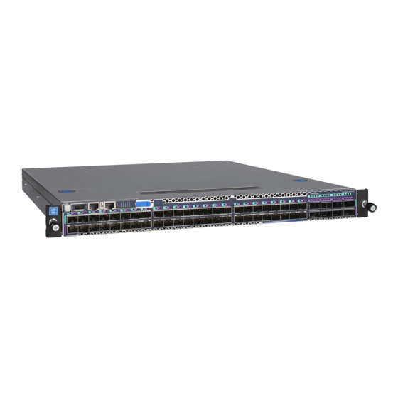
Page 6: Model M4500-48Xf8C
Item USB Port System Info. LED Console Port Power LED Link/Activity LED BMC LED Management Port SFP28 Port LEDs PSU1 LED SFP28 Ports Fan LED QSFP28 Port LEDs PSU2 LED QSFP28 Ports NETGEAR M4500 Series Switches Hardware Installation Guide 6... - Page 7 On the rear panel, the left power supply is PSU2 and the right power supply is PSU1. The fan modules from the left to the right are FAN6, FAN5, FAN4, FAN3, FAN2, and FAN1. 7 NETGEAR M4500 Series Switches Hardware Installation Guide...
-
Page 8: Led Indicators Of Model M4500-48Xf8C
A “show switch location” occurred via the BMC Blinking) Green (Solid) The switch has loaded the agent software code and is operating normally Green (Blinking) The switch is loading the agent software code NETGEAR M4500 Series Switches Hardware Installation Guide 8... - Page 9 The port is linked, and there is data activity at 100G speed Blue (Solid) The port is linked at 40G speed Blue (Blinking) The port is linked at 40G speed and there is data activity at 40G speed 9 NETGEAR M4500 Series Switches Hardware Installation Guide...
-
Page 10: Ports Of Model M4500-48Xf8C
One console port enables you to perform the initial configuration by connecting to a PC with the RJ-45 to DB-9 serial adapter cable. One USB port provides the option to install a switch runtime image or configuration file into storage memory. NETGEAR M4500 Series Switches Hardware Installation Guide 10... -
Page 11: Data Port Connection
SFP+ Active DAC 7m AXC7610 SFP+ Active DAC 10m AXC7615 SFP+ Active Optical DAC 15m AXC7620 SFP+ Active Optical DAC 20m NOTE: For more information about NETGEAR transceiver modules and cables, visit https://www.netgear.com/business/products/switches/modules-accessories/. 11 NETGEAR M4500 Series Switches Hardware Installation Guide... - Page 12 Push completely until the module locks into place. Repeat the above procedures to install additional QSFP28 modules. For more information about the QSFP28 port LED behavior when the network link is established, refer to “LED indicators of model M4500-48XF8C”. NETGEAR M4500 Series Switches Hardware Installation Guide 12...
-
Page 13: Fan Tray Of Model M4500-48Xf8C
Fan tray of model M4500-48XF8C The switch chassis is equipped with six fan trays. Each fan module provides front-to-back airflow and is hot-swappable. The NETGEAR model number for a fan module is AFT402. NOTE: To hot-swap the fan during operation, make sure to replace it within 30 seconds. -
Page 14: Airflow Direction
The air intake is located on the front panel of the switch. The cool air is sucked in from outside the chassis and pushed toward the rear of the chassis. The hot air exhausts through the vents on the rear panel of the switch. NETGEAR M4500 Series Switches Hardware Installation Guide 14... -
Page 15: Model M4500-32C
Item QSFP28 Port LEDs System Info. LED QSFP28 Ports Power LED USB Port BMC LED Console Port Speed LED PSU1 LED Management Port Fan LED Link/Activity LED PSU2 LED None Fan-out Port NETGEAR M4500 Series Switches Hardware Installation Guide 15... - Page 16 On the rear panel, the left power supply is PSU2 and the right power supply is PSU1. The fan modules from the left to the right are FAN6, FAN5, FAN4, FAN3, FAN2, and FAN1. NETGEAR M4500 Series Switches Hardware Installation Guide 16...
-
Page 17: Led Indicators Of Model M4500-32C
A “show switch location” occurred via the BMC Blinking) Green (Solid) The switch has loaded the agent software code and is operating normally Green (Blinking) The switch is loading the agent software code 17 NETGEAR M4500 Series Switches Hardware Installation Guide... - Page 18 The port is linked, and there is data activity at 100G speed Blue (Solid) The port is linked at 40G speed Blue (Blinking) The port is linked at 40G speed and there is data activity at 40G speed NETGEAR M4500 Series Switches Hardware Installation Guide 18...
-
Page 19: Ports Of Model M4500-32C
One console port enables you to perform the initial configuration by connecting to a PC with the RJ-45 to DB-9 serial adapter cable. One USB port provides the option to install a switch runtime image or configuration file into storage memory. 19 NETGEAR M4500 Series Switches Hardware Installation Guide... -
Page 20: Data Port Connection
SFP+ Active DAC 7m AXC7610 SFP+ Active DAC 10m AXC7615 SFP+ Active Optical DAC 15m AXC7620 SFP+ Active Optical DAC 20m NOTE: For more information about NETGEAR transceiver modules and cables, visit https://www.netgear.com/business/products/switches/modules-accessories/. NETGEAR M4500 Series Switches Hardware Installation Guide 20... -
Page 21: Fan Tray Of Model M4500-32C
Fan tray of model M4500-32C The switch chassis is equipped with six fan trays. Each fan module provides front-to-back airflow and is hot-swappable. The NETGEAR model number for a fan module is AFT402. NOTE: To hot-swap the fan during operation, make sure to replace it within 30 seconds. -
Page 22: Airflow Direction
The AC power connector is a standard three-pronged connector. The switch automatically adjusts its power setting to any supply voltage in the range from 100~240 VAC at 50~60 The NETGEAR model number for a PSU is APS750W. NOTE: Verify that each module has the same airflow direction. Make sure the switch runs with all of its power supply and fan tray modules taking in air from a cold aisle and exhausting air to the hot aisle. -
Page 23: Hardware Installation
The following items are included with a standard package. When you open the box, check if all items are included and free of damage. One Netgear M4500 Intelligent Fully Managed Switch Depending on the product ordered, two or four AC power cords ... -
Page 24: Positioning The Switch
Due to the switch’s weight, it should be installed by at least two people. Items Required for Installation The following items are required to install the switch onto the rack: Phillips screwdriver Screws that fit the equipment rack NETGEAR M4500 Series Switches Hardware Installation Guide 24... - Page 25 For each inner rail, pull the tab upward to unlock the latch, and then push the middle rail back into the outer rail. Remove the screws on the switch. NOTE: Place the screws in a bag to prevent losing them. 25 NETGEAR M4500 Series Switches Hardware Installation Guide...
- Page 26 For each inner rail, align the hooks on the switch with the holes in the inner rail, and then slide the inner rail backward until it is locked in place. For each inner rail, use the screws to secure the inner rail to the switch. NETGEAR M4500 Series Switches Hardware Installation Guide 26...
- Page 27 Pull the middle rails out until they are fully extended, ensuring that the ball bearing retainers are locked at the front of the middle rails. Slide the inner rails on the switch into the middle rails until the movement stops. 27 NETGEAR M4500 Series Switches Hardware Installation Guide...
-
Page 28: Connecting To The Console Port
Configure the switch by using the Command Line Interface (CLI) Manage and monitor network activity by using the CLI Manage and monitor network activity by using Simple Network Management Protocol (SNMP) Upgrade the firmware NETGEAR M4500 Series Switches Hardware Installation Guide 28... -
Page 29: Connecting To The Management Port
For more information on how to configure the switch, see the CLI manual. To connect to the management port: Connect one end of an Ethernet cable to the management port ( ) of the switch. Model M4500-48XF8C Model M4500-32C 29 NETGEAR M4500 Series Switches Hardware Installation Guide... -
Page 30: Connecting The Power
The switch has no power button. Once an AC power cord is connected to a power outlet, the switch power is turned on. The Power LED lights green. For details, refer to “PSU LEDs”. NETGEAR M4500 Series Switches Hardware Installation Guide 30... -
Page 31: Components Replacement
Verify that all system components have been properly installed. If one or more components appear to be malfunctioning (such as the power cord or network cabling), test them in an alternate environment where you are sure that all the other components are functioning properly. NETGEAR M4500 Series Switches Hardware Installation Guide 31... -
Page 32: In-Band Access
PSU. Ensure the power supply unit is correctly oriented, then install the new PSU into the chassis until it is firmly seated. Connect the AC power cord to power on the switch. NETGEAR M4500 Series Switches Hardware Installation Guide 32... -
Page 33: Replacing The Fan Tray
Ensure the fan module is correctly oriented, then install the new fan module into the chassis until it is firmly seated. 33 NETGEAR M4500 Series Switches Hardware Installation Guide...