Table of Contents
Advertisement
Advertisement
Table of Contents
Troubleshooting

Related Manuals for Juniper QFX5220


Summary of Contents for Juniper QFX5220
- Page 1 QFX5220 Switch Hardware Guide Published 2019-11-07...
- Page 2 END USER LICENSE AGREEMENT The Juniper Networks product that is the subject of this technical documentation consists of (or is intended for use with) Juniper Networks software. Use of such software is subject to the terms and conditions of the End User License Agreement (“EULA”) posted at https://support.juniper.net/support/eula/.
-
Page 3: Table Of Contents
Creating a Service Request with JTAC | xvii Overview QFX5220 System Overview | 21 QFX5220-128C Switch Description | 21 Benefits of the QFX5220-128C | 22 QFX5220-32CD Switch Description | 23 Benefits of the QFX5220-32CD | 23 QFX5220 Hardware Component Overview | 24... - Page 4 QFX5220-32CD Fan Module LED | 58 Fan Module Status | 59 QFX5220 Power System | 61 QFX5220 AC Power Supply Modules Description | 63 QFX5220 AC Power Specifications | 65 AC Power Cord with Type C13 Coupler Specifications | 66...
- Page 5 QFX5220 Environmental Requirements and Specifications | 83 General Site Guidelines | 84 QFX5220 Grounding Cable and Lug Specifications | 85 QFX5220 Clearance Requirements for Airflow and Hardware Maintenance | 86 QFX5220 Chassis Physical Specifications | 87 Site Electrical Wiring Guidelines | 87...
- Page 6 Unpacking and Mounting the QFX5220 | 112 Unpacking a QFX5220 | 113 Registering Products—Mandatory for Validating SLAs | 115 Mounting a QFX5220 in a Rack or Cabinet | 116 Before You Begin Rack Installation | 117 Four-Post Installation Procedure for QFX5220-128C | 118...
- Page 7 Maintaining the QFX5220 Power System | 157 How to Remove a Power Supply from a QFX5220 | 157 How to Install an AC Power Supply in a QFX5220 | 160 Maintaining Transceivers and Fiber Optic Cables on a QFX5220 | 163...
- Page 8 Returning a Hardware Component to Juniper Networks, Inc. | 198 Guidelines for Packing Hardware Components for Shipment | 199 Packing a QFX5220 Device or Component for Shipping | 199 Packing a QFX5220 Switch for Shipping | 200 Packing QFX5220 Components for Shipping | 201...
- Page 9 DC Power Wiring Sequence Warning | 245 DC Power Wiring Terminations Warning | 248 Multiple Power Supplies Disconnection Warning | 251 TN Power Warning | 252 Agency Approvals and Compliance Statements for the QFX5200 and QFX5220 | 252 Agency Approvals for the QFX Series | 253...
-
Page 10: About The Documentation
If the information in the latest release notes differs from the information in the documentation, follow the product Release Notes. Juniper Networks Books publishes books by Juniper Networks engineers and subject matter experts. These books go beyond the technical documentation to explore the nuances of network architecture, deployment, and administration. -
Page 11: Merging A Full Example
If the example configuration contains the top level of the hierarchy (or multiple hierarchies), the example is a full example. In this case, use the load merge command. If the example configuration does not start at the top level of the hierarchy, the example is a snippet. In this case, use the load merge relative command. -
Page 12: Merging A Snippet
xiii Merging a Snippet To merge a snippet, follow these steps: 1. From the HTML or PDF version of the manual, copy a configuration snippet into a text file, save the file with a name, and copy the file to a directory on your routing platform. For example, copy the following snippet to a file and name the file ex-script-snippet.conf. - Page 13 Table 1: Notice Icons Icon Meaning Description Informational note Indicates important features or instructions. Caution Indicates a situation that might result in loss of data or hardware damage. Warning Alerts you to the risk of personal injury or death. Laser warning Alerts you to the risk of personal injury from a laser.
- Page 14 Table 2: Text and Syntax Conventions (continued) Convention Description Examples Italic text like this Represents variables (options for Configure the machine’s domain which you substitute a value) in name: commands or configuration [edit] statements. root@# set system domain-name domain-name Text like this Represents names of configuration To configure a stub area, include statements, commands, files, and...
-
Page 15: Documentation Feedback
URL or page number, and software version (if applicable). Requesting Technical Support Technical product support is available through the Juniper Networks Technical Assistance Center (JTAC). If you are a customer with an active Juniper Care or Partner Support Services support contract, or are... -
Page 16: Self-Help Online Tools And Resources
JTAC hours of operation—The JTAC centers have resources available 24 hours a day, 7 days a week, 365 days a year. Self-Help Online Tools and Resources For quick and easy problem resolution, Juniper Networks has designed an online self-service portal called the Customer Support Center (CSC) that provides you with the following features: Find CSC offerings: https://www.juniper.net/customers/support/... -
Page 17: Overview
C HAPTER Overview QFX5220 System Overview | 21 QFX5220-32CD Port Panel | 27 QFX5220-128C Port Panel | 32 QFX5220 Management Panel | 45 QFX5220 Cooling System | 52 QFX5220 Power System | 61... -
Page 19: Qfx5220 System Overview
Ethernet and 400-Gigabit Ethernet speeds. QFX5220-128C Switch Description The QFX5220-128C offers 128 ports of 100-Gigabit Ethernet in a 4-U form factor. With 12.8 terabits per second (Tbps) bandwidth, the QFX5220-128C is optimally designed as a data aggregation or top-of-rack switch for small to medium size data centers and Massively Scalable Data Center (MSDC) deployments. -
Page 20: Benefits Of The Qfx5220-128C
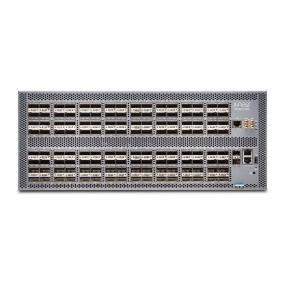
Figure 1: QFX5220-128C Front Panel Figure 2: QFX5220-128C FRU Panel Benefits of the QFX5220-128C Serves the spine layer needs of a wide range of enterprises. Examples include: cloud and high-performance computing data centers; Software as a Service (SaaS) providers; streaming video service providers; cable operators;... -
Page 21: Qfx5220-32Cd Switch Description
400 Gbps, 100 Gbps, 25 Gbps, 40 Gbps, and 10 Gbps. An Intel Xeon D-1500 processor drives the QFX5220 control plane, which runs the Junos OS Evolved software. The Junos OS Evolved software image is stored on two internal 50-GB solid-state drives (SSDs). -
Page 22: Qfx5220 Hardware Component Overview
Allows current Junos OS users to seamlessly migrate to Junos OS Evolved Linux software. With Junos OS Evolved, you can run Linux using your familiar Junos OS CLI, and run third-party Linux applications with Juniper Extension Toolkit (JET) API support, telemetry support for monitoring the DC network, and support for module-level in-service software upgrade (ISSU). -
Page 23: System Software
AFI airflow. System Software The Junos OS Evolved software on the QFX5220 provides Layer 2 and Layer 3 switching, routing, and security services. Junos OS Evolved is installed on the switch solid-state drive (SSD). For more information about which features are supported on QFX Series devices, see Feature Explorer. -
Page 24: Qfx5220 Field-Replaceable Units
QFX5220-32CD within the desired temperature thresholds, chassis alarms occur and the QFX5220-32CD switch can shut down. QFX5220-128C cooling system—This switch model has 12 fans in 6 fan modules. There is one fan out of the 12 fans for redundancy. This is known as (5x2+1)+1 redundancy). Any additional fan failures cause the switch to overheat, chassis alarms to occur and shutdown the switch. -
Page 25: Qfx5220-32Cd Port Panel
Disconnecting a Fiber-Optic Cable. NOTE: If you have a Juniper Care service contract, register any addition, change, or upgrade of hardware components at https://www.juniper.net/customers/support/tools/updateinstallbase/. Failure to do so can result in significant delays if you need replacement parts. This note does not apply if you replace existing components with the same type of component. -
Page 26: Network Ports
The port panel of the QFX5220-32CD has 32 high-speed ports that support transmission at 400-Gbps, 100-Gbps, or 25-Gbps speeds. It also has 2 dedicated ports for 10 Gbps. CO N M GM T RES ET RJ-45 connection to grandmaster clock Reset button (do not use unless directed by JTAC) —... - Page 27 0 pic 0 port 2 speed 100g NOTE: On QFX5220-32CD devices, there is a single FPC and PIC, which is always 0. After you set a port speed, you can channelize the port into 4 independent 25-Gigabit Ethernet interfaces by configuring the number of subports and speed.
-
Page 28: Qfx5220-32Cd Network Leds
LED for the high-speed ports. Table 7 on page 31 describes how to interpret the link and activity LED and the status LEDs for the SFP+ ports. Table 6: QSFP-DD Network Port LEDs on a QFX5220-32CD Color State Channelized... - Page 29 Table 6: QSFP-DD Network Port LEDs on a QFX5220-32CD (continued) Color State Channelized Description Green On steadily A 400-Gbps or 100-Gbps link is established, but there is no activity. All channels or subports have link established but there is no activity.
-
Page 30: Qfx5220-128C Port Panel
QFX5220-128C Network LEDs | 42 Overview The port panel of the QFX5220-128C consists of 128 high-density 100-Gigabit Ethernet quad small form-factor pluggable solution (QSFP28) ports and the management panel. The highly flexible ports support 100-Gbps or 40-Gbps port speeds; 100-Gbps speed is the default, 40G-Gbps must be configured. The QFX5220-128C supports channelizing the QSFP28 ports to 4 independent 25-Gbps speed interfaces. -
Page 31: Network Ports
— ports. (The LEDs indicate status and link.) Network Ports The QFX5220-128C QSFP28 network ports (0 to 127) support: 100-Gbps QSFP28 transceivers 100-Gbps QSFP28 direct attach copper (DAC) cables 100-Gbps QSFP28 to 25-Gbps SFP28 direct attach copper break out (DACBO) cables (100-Gbps breaks... -
Page 32: Port Configurations
The 10-Gbps network ports 128 (et-0/0/128) and 129 (et-0/0/129) support SFP+ transceivers. Port Configurations The QFX5220-128C has 128 QSFP28 ports and 2 SFP+ ports. You can configure any of these ports in these combinations: Any of the QSFP28 ports can be configured as 100 Gbps. - Page 33 Table 8: QFX5220-128C Valid 100-Gbps Configurations (continued) Ports Configurable as Ports Configurable as 40 Ports Configurable as channelized 4 x 25 Port 100 Gbps Gbps Gbps Configure as unused Configure as unused Configure as unused Configure as unused Configure as unused...
- Page 34 Table 8: QFX5220-128C Valid 100-Gbps Configurations (continued) Ports Configurable as Ports Configurable as 40 Ports Configurable as channelized 4 x 25 Port 100 Gbps Gbps Gbps Configure as unused Configure as unused Configure as unused Configure as unused Configure as unused...
- Page 35 Table 8: QFX5220-128C Valid 100-Gbps Configurations (continued) Ports Configurable as Ports Configurable as 40 Ports Configurable as channelized 4 x 25 Port 100 Gbps Gbps Gbps Configure as unused Configure as unused Configure as unused Configure as unused Configure as unused...
- Page 36 Table 8: QFX5220-128C Valid 100-Gbps Configurations (continued) Ports Configurable as Ports Configurable as 40 Ports Configurable as channelized 4 x 25 Port 100 Gbps Gbps Gbps Configure as unused Configure as unused Configure as unused Configure as unused Configure as unused...
- Page 37 Table 8: QFX5220-128C Valid 100-Gbps Configurations (continued) Ports Configurable as Ports Configurable as 40 Ports Configurable as channelized 4 x 25 Port 100 Gbps Gbps Gbps Configure as unused Configure as unused Configure as unused Configure as unused Configure as unused...
- Page 38 Table 8: QFX5220-128C Valid 100-Gbps Configurations (continued) Ports Configurable as Ports Configurable as 40 Ports Configurable as channelized 4 x 25 Port 100 Gbps Gbps Gbps Configure as unused Configure as unused Configure as unused Configure as unused Configure as unused...
-
Page 39: 100-Gbps Port Configuration
Table 8: QFX5220-128C Valid 100-Gbps Configurations (continued) Ports Configurable as Ports Configurable as 40 Ports Configurable as channelized 4 x 25 Port 100 Gbps Gbps Gbps Configure as unused Configure as unused Configure as unused Configure as unused Configure as unused 100-Gbps Port Configuration All QSFP28 ports work by default as 100 Gbps. -
Page 40: X 25 Gbps Port Channelization
# commit Delete 4 x 25 Gbps or 4 x 10 Gbps Port Channelization To remove the channelization configuration from a set of QFX5220-128C ports, delete the configuration from the channelized port and commit the configuration. For example: # delete chassis fpc 0 pic 0 port port-number number-of-sub-ports 4... - Page 41 LEDs for the QSFP28 ports and Table 10 on page 44 describe the LED states for the SFP+ ports. Table 9: Network Port LEDs on QSFP28 Ports on a QFX5220-128C Switch Color State Non-Channelized...
- Page 42 Table 9: Network Port LEDs on QSFP28 Ports on a QFX5220-128C Switch (continued) Color State Non-Channelized Channelized Amber On steadily At least one, but not all sub-channels are up. Blinking There is an interface error. There is an error on one or more sub-channels.
-
Page 43: Qfx5220 Management Panel
The management panel allows you to have a management channel into the switch that is separate from production traffic. QFX5220-128C Management Panel Overview The management panel of the QFX5220-128C is located to the right of the network ports. Figure 8 on page 46 shows the connections and components of the management panel and the network... -
Page 44: Qfx5220-32Cd Management Panel Overview
RJ-45 console (CON) port — QFX5220-32CD Management Panel Overview The management panel of the QFX5220-32CD is divided in two sections, with the port panel in between these sections. Figure 9 on page 47 shows the connections and components of the management panel... -
Page 45: Qfx5220-32Cd Management Panel Leds
Figure 9: QFX5220-32CD Port and Management Panels CO N M GM T RES ET RJ-45 grandmaster time-of-day connection Reset button (do not use unless under the direction — — of JTAC) Chassis alarms LEDs Slide out tab for chassis serial number —... -
Page 46: Qfx5220 Chassis Status Leds
QFX5220 Chassis Status LEDs Both models of the QFX5220 have a series of three LEDs that indicate system status. On the QFX5220-128C, you can find these LEDs to the right of the network ports (see Figure 10 on page 48). - Page 47 ----------------------------------- LEDs status: Alarm LED : Red Beacon LED: Off System LED: Green Interface STATUS LED LINK/ACTIVITY LED --------------------------------------------------------- et-0/0/0 et-0/0/1 et-0/0/2 et-0/0/3 et-0/0/4 et-0/0/5 et-0/0/6 et-0/0/7 et-0/0/8 et-0/0/9 et-0/0/10 Green et-0/0/11 et-0/0/12 et-0/0/13 et-0/0/14 et-0/0/15 et-0/0/16 Green et-0/0/17 et-0/0/18 Green et-0/0/19 et-0/0/20...
- Page 48 Table 11: Chassis Status LEDs on a QFX5220-Devices Name Color State Description ALM–Alarm Unlit The switch is halted or there is no alarm. On steadily A major hardware fault has occurred, such as a temperature alarm, power failure, or media failure. The device has halted.
-
Page 49: Rj-45 Management Port Leds
0 FPC 0 RJ-45 Management Port LEDs The management port on a QFX5220-32CD has two LEDs that indicate link status and link activity. The management port is labeled MGMT for 10/100/1000BASE-T connections. CO N M GM T... -
Page 50: Qfx5220 Cooling System
QFX5220-128C Cooling System Description IN THIS SECTION Fan Modules | 52 The cooling system in an QFX5220-128C consists of six 80-W fan modules and two counter-rotating fans housed in each of the four power supplies. Fan Modules The fan modules in a QFX5220-128C are hot-removable and hot-insertable FRUs designed for port-to-FRU airflow. - Page 51 Figure 12: Fan module for QFX5220-128C The QFX5220-128C brings air into the vents in the port panel and exhausts warmed air through the field-replaceable units (FRU) panel. This type of airflow is know as airflow out or port-to-FRU airflow. Airflow out fans are distinguished by AIR OUT marking on the orange (Juniper gold) handles.
-
Page 52: Qfx5220-128C Fan Module Led
QFX5220-128C Fan Module LED Each fan module has an associated LED to indicate status. On the QFX5220-128C, the fan LED is located to the right of each fan below a fan icon. See Figure 14 on page 54 for the location of these LEDs. -
Page 53: Fan Modules
The cooling system in an QFX5220-32CD consists of six fan modules and a single fan in each power supply. The switch can ordered in one of two airflow directions: Airflow In–Air comes into the switch through the vents in the field-replaceable units (FRUs) Airflow Out–Air comes into the switch through the vents in the port panel. - Page 54 Table 13: Fan Modules in QFX5220 Switches Label on Color of the Fan Direction of Airflow Power Fan Module Airflow Diagram Module Module in the Fan Module Supplies QFX5220-32CD-FANAI Figure16onpage57 AIR IN Juniper FRU-to-port, that is, You must azure blue...
-
Page 55: Do Not Install Components With Different Airflow Or Wattage In The Switch
The handles on Airflow In fans and power supplies are azure blue, compared to the Airflow Out fans and power supplies, which are Juniper gold. Mixing components with different airflows in the same chassis hampers the performance of the cooling... -
Page 56: Qfx5220-32Cd Fan Module Led
Do not mix AC and DC power supplies in the same QFX5220 chassis. However, if you need to convert a QFX5220 device to have a different airflow, you can change the airflow pattern. To convert an AIR IN product variant to an AIR OUT product variant or an AIR OUT product variant to a AIR IN product variant, you must power off and replace all of the fans and power supplies at one time to use the new direction. -
Page 57: Fan Module Status
Figure 18: Fan Module LEDs on a QFX5220-32CD Fan module LED — Table 14 on page 59 describes the function of the fan tray LED. Table 14: Fan Tray LED Behavior in a QFX5220 Name Color State Description Green On steadily The fan module is operating normally. - Page 58 Class Item Status Measurement Temp PSM 1 25 degrees C / 77 degrees F PSM 3 25 degrees C / 77 degrees F FPC 0 Sensor MainTopBack 32 degrees C / 89 degrees F FPC 0 Sensor MainTopBackRight 32 degrees C / 89 degrees F FPC 0 Sensor MezzPhysLeftSide 26 degrees C / 78 degrees F FPC 0 Sensor MezzPhysRightSide Ok...
-
Page 59: Qfx5220 Power System
Fan Tray 5 Fan 1 4395 RPM Fan Tray 5 Fan 2 4981 RPM The QFX5220 has a status LED (labeled ST) for each fan module. It indicates the status of all the fan modules. RELATED DOCUMENTATION Maintaining QFX5220 Cooling System | 153... - Page 60 (FRUs). You can install replacement power supplies without powering off the device or disrupting switching function. The power supplies are installed at the factory and shipped with the chassis. All power supplies for QFX5220 are 1600 W; however, the power supplies for the QFX5220-32CD and the QFX5220-128C are not interchangeable.
-
Page 61: Qfx5220 Ac Power Supply Modules Description
The QFX5220-32CD ships with two power supplies; the QFX5220-128C ships with four power supplies. While each model can operate with the minimum number of power supplies (one for QFX5220-32CD, two for QFX5220-128C), maximum power supplies are required to have redundancy. See... - Page 62 Handle — — An AC power supply for the QFX5220 is 1600 W. However, the power supplies for the QFX5220-32CD and the QFX5220-128C are not interchangeable. Be sure to use the correct power supply for your chassis product variant (see Table 15 on page 64).
-
Page 63: Qfx5220 Ac Power Specifications
To avoid electrical injury, carefully follow instructions in “Connecting the QFX5220 to Power” on page 136. QFX5220 AC Power Specifications Table 16 on page 65 describes the AC power specifications for a QFX5220. Table 16: AC Power Specifications for a QFX5220 Item Specification AC input voltage... -
Page 64: Ac Power Cord With Type C13 Coupler Specifications
115-127 V: 973-W QFX5220-128C 115-127 V: 2023-W 220-240 V: 1990-W QFX5220-128C AC models use power cords with type C15 couplers, see “AC Power Cord with Type C15 Coupler Specifications” on page 68. The QFX5220-32CD AC model uses power cords with type C13 couplers, see “AC Power Cord with Type C13 Coupler Specifications”... - Page 65 Table 17: AC Power Cord Specifications Electrical Plug Shipped Juniper Spare Juniper Model Country/Region Specifications Standards Model Number Number Graphic Australia 250 VAC, 10 A, AS/NZ CG_CBL-C13-06-AU CBL-EX-PWR-C13-AU 50 Hz 3109-1996 China 250 VAC, 10 A, GB 1002-1996 CG_CBL-C13-06-CH CBL-EX-PWR-C13-CH...
-
Page 66: Ac Power Cord With Type C15 Coupler Specifications
AC Power Cord with Type C15 Coupler Specifications Detachable AC power cords are shipped with the chassis, if you include them as part of your order. Some country-specific plugs are only available as spare orders. The coupler is type C15 as described by International Electrotechnical Commission (IEC) standard 60320. - Page 67 Table 18: AC Power Cord Specifications Electrical Juniper Model Spare Juniper Model Country/Region Specifications Plug Standards Number Number Graphic Argentina 250 VAC, 10 A, IRAM 2073 Type – CBL-PWR-C15M-HITEMP-AR 50 Hz RA/3 Australia 250 VAC, 10 A, AS/NZS CG_CBL-C15-02-AU CBL-PWR-C15M-HITEMP-AU...
-
Page 68: Qfx5220 Ac Power Supply Leds
General Electrical Safety Guidelines and Warnings | 234 Prevention of Electrostatic Discharge Damage | 235 QFX5220 AC Power Supply LEDs The QFX5220-128C uses a single bi-colored LED to indicate power status. Figure 23 on page 70 shows the location of the LED on the JPSU-1600W-AC-AFO and... -
Page 69: Qfx5220 Dc Power Supply Description
The factory installed power supplies in both models are 1600-W, but are not interchangeable. The QFX5220-128C switch has four power supplies and the QFX5220-32CD is shipped with two power supplies. Each power supply provides 2400 W of power to the chassis. - Page 70 Figure 25: DC Power Supply in QFX5220-128C Power LED Handle — — Ejector lever — Figure 26: DC Power Supply in QFX5220-32CD CAUTION: Verify that the airflow direction on the power supply handle matches the direction of airflow in the chassis. Ensure that each power supply you install in the chassis has the same airflow direction.
-
Page 71: Qfx5220 Dc Power Specifications
“Maintaining the QFX5220 Power System” on page 157 QFX5220 DC Power Specifications Table 21 on page 73 describes the DC power specifications for the DC version of a QFX5220 switch. Table 21: DC Power Specifications for a QFX5220 Item Model... -
Page 72: Qfx5220-128C Dc Power Cable Specification
QFX5220-128C DC Power Cable Specification QFX5220-128C DC power supplies require a D-Sub 3W3- type connector. The three pins on the connector provide –48 VDC input (–), return (+), and ground connections to the power supply. DC power cables, each 4 m (approximately 13.1 ft) long, are supplied with the QFX5220-128C. The provided cables include the three-pin connector on one end and three insulated wires at the opposite end, for connection to the site’s DC power distribution system. -
Page 73: Qfx5220-128C Dc Power Supply Led
QFX5220-128C DC Power Supply LED Figure 27 on page 75 shows the location of the status LED on the QFX5220-128C DC power supply. Figure 27: DC Power Supply LED Status LED — Table 23 on page 75 describes the status LED behavior on QFX5220-128C power supplies. -
Page 74: Qfx5220-32Cd-D Dc Power Supply Led
Figure 28 on page 76 shows the location of the power supply status LEDs. Figure 28: QFX5220-32CD-D Status LEDs Input OK Fault — — Output OK — Table 24 on page 77 describes the status LED behavior on QFX5220-32CD power supplies. - Page 75 Table 24: DC Power Supply LEDs on a QFX5220-32CD Status LED Color Description Input OK The power supply is disconnected from power, or power is not coming into the power supply. Green, on steadily Input voltage is present and is within range.
-
Page 76: Site Planning, Preparation, And Specifications
C HAPTER Site Planning, Preparation, and Specifications QFX5220 Site Preparation Checklist | 81 QFX5220 Site Guidelines and Requirements | 82 QFX5220 Network Cable and Transceiver Planning | 91 QFX5220 Management Cable Specifications and Pinouts | 98... -
Page 78: Qfx5220 Site Preparation Checklist
QFX5220 Site Preparation Checklist The checklist in Table 25 on page 81 summarizes the tasks you need to perform when preparing a site for a QFX5220 installation. Table 25: Site Preparation Checklist Item or Task For More Information Performed By... -
Page 79: Qfx5220 Site Guidelines And Requirements
QFX5220 Environmental Requirements and Specifications | 83 General Site Guidelines | 84 QFX5220 Grounding Cable and Lug Specifications | 85 QFX5220 Clearance Requirements for Airflow and Hardware Maintenance | 86 QFX5220 Chassis Physical Specifications | 87 Site Electrical Wiring Guidelines | 87... -
Page 80: Qfx5220 Environmental Requirements And Specifications
QFX5220-32CD-AFO–At 32° F through 104° F (0° C through 40° C) there is no performance degradation to 6000 feet (1828.8 meters) QFX5220-32CD-AFI-At 32° F through 77° F (0° C through 25° C) there is no performance degradation to 6000 feet (1828.8 meters) -
Page 81: General Site Guidelines
Table 26: QFX5220-32CD Switch Environmental Tolerances (continued) Description Tolerance Temperature QFX5220-128C-AFO Normal operation ensured in temperature range of 32° F through 104° F (0° C through 40° C) Nonoperating storage temperature in shipping container: –40° F through 158° F (–40° C through 70° C) QFX5220-32CD-AFO Normal operation ensured in temperature range of 32°... -
Page 82: Qfx5220 Grounding Cable And Lug Specifications
(not provided). The grounding lug should accommodates 14–10 AWG (2–5.3 mm²) stranded wire. The grounding cable that you provide for a QFX5220 must be 14 AWG (2 mm²), minimum 60° C wire, or as permitted by the local code. -
Page 83: Qfx5220 Clearance Requirements For Airflow And Hardware Maintenance
QFX5220 Clearance Requirements for Airflow and Hardware Maintenance When planning the site for installing a QFX5220, you must allow sufficient clearance around the installed chassis (see Figure 29 on page 86 Figure 30 on page 86). Figure 29: Clearance Requirements for Airflow and Hardware Maintenance for a QFX5220-32CD 30 in. -
Page 84: Qfx5220 Chassis Physical Specifications
Leave at least 24 in. (61 cm) both in front of and behind the QFX5220. For service personnel to remove and install hardware components, you must leave adequate space at the front and back of the switch. -
Page 85: Qfx5220 Rack Requirements
Destruction of the signal drivers and receivers in the device Electrical hazards as a result of power surges conducted over the lines into the equipment QFX5220 Rack Requirements QFX5220 switches are designed to be installed on four-post racks. Rack requirements consist of: Rack type... -
Page 86: Qfx5220 Cabinet Requirements
Secure the rack to the ceiling brackets as well as wall or floor brackets for maximum stability. QFX5220 Cabinet Requirements You can mount the QFX5220 in an enclosure or cabinet that contains a four-post 19-in. open rack as defined in Cabinets, Racks, Panels, and Associated Equipment (document number EIA-310-D) published by... - Page 87 If the cabinet contains a top or doors, perforations in these elements assist with removing the hot air exhaust. The QFX5220 fans exhaust hot air either through the vents on the port panel or through the fans and power supplies. Install the switch in the cabinet in a way that maximizes the open space on the FRU side of the chassis.
-
Page 88: Qfx5220 Network Cable And Transceiver Planning
Calculating Power Budget and Power Margin for Fiber-Optic Cables | 95 Determining QFX5220 Optical Interface Support You can find information about the optical transceivers supported on your Juniper device by using the Hardware Compatibility Tool. In addition to transceiver and connection type, the optical and cable characteristics–where applicable–are documented for each transceiver. -
Page 89: Cable Specifications For Qsfp+ And Qsfp28 Transceivers
The 40-Gigabit Ethernet QSFP+ and 100-Gigabit Ethernet QSFP28 transceivers that are used in QFX Series switches use 12-ribbon multimode fiber crossover cables with female MPO/UPC connectors. The fiber can be either OM3 or OM4. These cables are not sold by Juniper Networks. CAUTION: To maintain agency approvals, use only a properly constructed, shielded cable. - Page 90 Table 31: QSFP+ and QSFP28 Optical Module Receptacle Pinouts (continued) Fiber Signal Rx1 (Receive) Rx0 (Receive) Table 32: QSFP+ MPO Fiber-Optic Crossover Cable Pinouts...
-
Page 91: Understanding Qfx Series Fiber-Optic Cable Signal Loss, Attenuation, And Dispersion
Understanding QFX Series Fiber-Optic Cable Signal Loss, Attenuation, and Dispersion IN THIS SECTION Signal Loss in Multimode and Single-Mode Fiber-Optic Cables | 94 Attenuation and Dispersion in Fiber-Optic Cable | 94 To determine the power budget and power margin needed for fiber-optic connections, you need to understand how signal loss, attenuation, and dispersion affect transmission. -
Page 92: Calculating Power Budget And Power Margin For Fiber-Optic Cables
You can use the Hardware Compatibility Tool to find information about the pluggable transceivers supported on your Juniper Networks device. To calculate the power budget and power margin, perform the following tasks: Calculating Power Budget for Fiber-Optic Cable | 96... -
Page 93: Calculating Power Budget For Fiber-Optic Cable
Calculating Power Budget for Fiber-Optic Cable To ensure that fiber-optic connections have sufficient power for correct operation, you need to calculate the link's power budget, which is the maximum amount of power it can transmit. When you calculate the power budget, you use a worst-case analysis to provide a margin of error, even though all the parts of an actual system do not operate at the worst-case levels. - Page 94 In both examples, the calculated power margin is greater than zero, indicating that the link has sufficient power for transmission and does not exceed the maximum receiver input power. RELATED DOCUMENTATION Maintaining Transceivers and Fiber Optic Cables on a QFX5220 | 163...
-
Page 95: Qfx5220 Management Cable Specifications And Pinouts
QFX5220 Management Cable Specifications and Pinouts IN THIS SECTION Cable Specifications for Console and Management Connections for the QFX Series | 98 RJ-45 Management Port Connector Pinout Information | 99 Console Port Connector Pinouts for the QFX Series | 99... -
Page 96: Rj-45 Management Port Connector Pinout Information
1000BASE-T operation RJ-45 Management Port Connector Pinout Information Table 35 on page 99 provides the pinout information for the RJ-45 connector for the management port on Juniper Networks devices. Table 35: RJ-45 Management Port Connector Pinout Information Signal Description TRP1+ Transmit/receive data pair 1 TRP1—... -
Page 97: Qsfp-Dd Port Connector Pinout Information
Table 36 on page 100 provides the pinout information for the RJ-45 console connector. An RJ-45 cable and RJ-45 to DB-9 adapter are supplied with the QFX Series device. NOTE: If your laptop or PC does not have a DB-9 male connector pin and you want to connect your laptop or PC directly to a QFX Series device, use a combination of the RJ-45 cable and RJ-45 to DB-9 adapter supplied with the device and a USB to DB-9 male adapter. - Page 98 Table 37: QSFP-DD Network Port Pinout Mapping (continued) Symbol Description TX2p Transmitter non-inverted data input Ground TX4n Transmitter inverted data input TX4p Transmitter non-inverted data input Ground ModSelL Module select ResetL Module reset VCC RX +3.3V Power Supply Receiver 2-wire serial interface clock 2-wire serial interface data Ground RX3p...
- Page 99 Table 37: QSFP-DD Network Port Pinout Mapping (continued) Symbol Description RX4n Receiver inverted data output RX4p Receiver non-inverted data output Ground ModPrsL Module Present IntL Interrupt VCC TX +3.3V power supply transmitter VCC1 +3/3V power supply LPMode Low power mode Ground TX3p Transmitter non-inverted data input...
- Page 100 Table 37: QSFP-DD Network Port Pinout Mapping (continued) Symbol Description Ground Not used Not used +3.3V power supply Reserved Reserved Ground RX7p Receiver non-inverted data output RX7n Receiver inverted data output Ground RX5p Receiver non-inverted data output RX5n Receiver inverted data output Ground Ground RX6n...
-
Page 101: Qsfp+, Qsfp28, And Qsfp56 Port Connector Pinout Information
Table 37: QSFP-DD Network Port Pinout Mapping (continued) Symbol Description Reserved +3.3V power supply +3.3V power supply Reserved Ground TX7p Transmitter non-inverted data input TX7n Transmitter inverted data input Ground TX5p Transmitter non-inverted data input TX5n Transmitter inverted data input Ground QSFP+, QSFP28, and QSFP56 Port Connector Pinout Information Table 38 on page 104... - Page 102 Table 38: QSFP+, QSFP28, and QSFP56 Port Connector Pinout Mappng (continued) Symbol Description TX4n Transmitter inverted data input TX4p Transmitter non-inverted data input Ground ModSelL Module select LPMode_Reset Low power mode reset VccRx +3.3V power supply receiver 2-wire serial interface clock 2-wire serial interface data Ground RX3p...
-
Page 103: Sfp, Sfp+, And Sfp28 Port Connector Pinout Information
Table 38: QSFP+, QSFP28, and QSFP56 Port Connector Pinout Mappng (continued) Symbol Description Ground ModPrsL Module Present IntL Interrupt VccTx +3.3V power supply transmitter Vcc1 +3/3V power supply Reserved Ground TX3p Transmitter non-inverted data input TX3n Transmitter inverted data input Ground TX1p Transmitter non-inverted data input... - Page 104 Table 39: SFP, SFP+, and SFP28 Port Connector Pinout Mapping (continued) Symbol Description TX_Disable Optical output disabled when high 2-wire serial interface data (MOD-DEF2) 2-wire serial interface data (MOD-DEF1) MOD_ABS Module absent Receiver rate select RX_LOS Receiver loss of signal indication Transmitter rate select VeeR Receiver ground...
-
Page 105: Usb Port Specifications For The Qfx Series
USB Port Specifications for the QFX Series The following Juniper Networks USB flash drives have been tested and are officially supported for the USB port in the QFX Series: RE-USB-1G-S—1-gigabyte (GB) USB flash drive (except QFX3100 Director device) RE-USB-2G-S—2-GB USB flash drive (except QFX3100 Director device) RE-USB-4G-S—4-GB USB flash drive... -
Page 106: Initial Installation And Configuration
Initial Installation and Configuration QFX5220 Installation Overview | 111 Unpacking and Mounting the QFX5220 | 112 Connecting the QFX5220 to External Devices | 128 Connecting the QFX5220 to Power | 136 Performing the Initial Software Configuration for QFX5220 Switches | 147... -
Page 108: Qfx5220 Installation Overview
“Unpacking a QFX5220” on page 113. 2. Determine how the switch is to be mounted. Flush or recessed mounted in a rack or cabinet, see “Mounting a QFX5220 in a Rack or Cabinet” on page 116. 3. Follow the instructions in:... -
Page 109: Qfx5220 Installation Safety Guidelines
The weight of a fully loaded QFX5220-32CD chassis is approximately 24.5 lb (11.11 kg) with power supplies and fans installed. The weight of a fully loaded QFX5220-128C is approximately 76 lbs (34 kg). Observe the following guidelines for lifting and moving a QFX5220: CAUTION: If you are installing the QFX5220 above 60 in. -
Page 110: Unpacking A Qfx5220
Unpacking a QFX5220 The QFX5220 chassis is a rigid sheet-metal structure that houses the hardware components. A QFX5220 is shipped in a cardboard carton, secured with foam packing material. CAUTION: The QFX5220 is maximally protected inside the shipping carton. Do not unpack the switch until you are ready to begin installation. - Page 111 Table 40: Inventory of Components Supplied with a QFX5220-32CD Device (continued) Component Quantity Rack mount kit for QFX5220-32CD Front mounting rail assembly, each composed of: Mounting rail Front flange Spacer Flathead screws (Phillips, 4-40x125 mm) Rear mounting blades Extension brackets...
-
Page 112: Registering Products-Mandatory For Validating Slas
(AC systems only) Documentation roadmap card Warranty Registering Products—Mandatory for Validating SLAs Register all new Juniper Networks hardware products and changes to an existing installed product using the Juniper Networks website to activate your hardware replacement service-level agreements (SLAs). -
Page 113: Mounting A Qfx5220 In A Rack Or Cabinet
Four-Post Installation Procedure for QFX5220-32CD | 120 You can mount QFX5220 switches only on a four-post 19-in. rack or cabinet using the rack mount kit provided with the switch. The rack mount kit can be adapted for either a four-post rack-only or a rack and cabinet installation. -
Page 114: Before You Begin Rack Installation
If you are installing the QFX5220 above 60 in. (152.4 cm) from the floor, you can remove the power supplies and fan modules to minimize the weight before attempting to install the device. -
Page 115: Four-Post Installation Procedure For Qfx5220-128C
Four-Post Installation Procedure for QFX5220-128C To mount the QFX5220-128C on a four-post rack using the provided rack mount kit: 1. Attach the ESD grounding strap to your bare wrist and to a site ESD point. 2. Decide whether the field replaceable unit (FRU) end of the switch or the port end is to be placed at the front of the rack. - Page 116 11. Have a second person secure the front of the switch to the rack using eight mounting screws (and cage nuts and washers if your rack requires them.) Tighten the screws. See Figure 33 on page 119 for an example of connecting the mounting rails and blades to a QFX5220-128C. Figure 33: Attach QFX5220-128C to Rack...
-
Page 117: Four-Post Installation Procedure For Qfx5220-32Cd
14. We recommend that you insert dust covers in any unused ports. Four-Post Installation Procedure for QFX5220-32CD To mount the QFX5220-32CD on a four-post rack using the provided rack mount kit: 1. Attach the ESD grounding strap to your bare wrist and to a site ESD point. - Page 118 Figure 36 on page 121 for an example of connecting the mounting rails and blades to a QFX5220-32CD. Figure 36: Attaching QFX5220-32CD to the Rack 8. Continue to support the switch while sliding the rear mounting-blades into the channel of the side mounting-rails and securing the blades to the rack.
-
Page 119: Four-Post Cabinet Installation For Qfx5220-32Cd
10. We recommend that you insert dust covers in any unused ports. Four-Post Cabinet Installation for QFX5220-32CD You can mount a QFX5220-32CD on four-post racks within a cabinet. For cabinet installations, you need to reconfigure the provided mounting rail. The mounting rail needs to be changed from a flush-mount to a set-back design to allow room in the cabinet for network cabling. - Page 120 Figure 38: Disassembling the Front Mounting Rail Front mounting bracket (you may discard for this Mounting rail — — procedure) Spacer — 4. Retain the spacer, the mounting rail, and the three flat-head Phillips machine screws for reuse in the extended mounting rail configuration, 5.
- Page 121 Figure 40 on page 124 to see the proper alignment for the QFX5220-32CD. Figure 40: Attaching the Mounting Rails to the QFX5220-32CD 8. Attach the mounting rail to the switch using six of the M4 Flat-head mounting screws (provided). Tighten the screws using a Phillips number 2 screwdriver.
-
Page 122: Emi Panel Installation On Qfx5220-128C
14. We recommend that you insert dust covers in any unused ports. EMI Panel Installation on QFX5220-128C The QFX5220-128C has an EMI front panel to protect fiber optic cabling and to provide additional protection from electromagnetic interference (EMI). The five in. deepEMI panel connects directly to the rack and can be added before or after optics are installed. - Page 123 A Phillips (+) screwdriver, number 2 (not provided) EMI panel (provided) Right mounting shelf (provided) Left mounting shelf (provided) Optional deflector ( 2 provided) Figure 43: QFX5220-128C Components Right and left mounting shelf EMI panel — — Deflectors, to help contain EMI emissions coming —...
- Page 124 Figure 44: Install Mounting Shelves 3. Tighten the top and bottom rack mount screws so that the mounting shelf is firmly attached to the rack. Repeat steps for the right mounting shelf. 4. Slide the door over the mounting shelves and tighten the four captive screws using the Phillips screwdriver, see Figure 45 on page 127.
-
Page 125: Connecting The Qfx5220 To External Devices
Ground the QFX5220-128C | 129 Connect Power to the QFX5220-128C | 129 Ground the QFX5220-32CD and Connect Power | 132 Connecting a Device to a Network for Out-of-Band Management | 133 Connecting a Device to a Management Console by Using an RJ-45 Connector | 134... -
Page 126: Ground The Qfx5220-128C
Connect Power to the QFX5220-128C The QFX5220-128C is shipped from the factory with four power supplies. Each power supply is a hot-removable and hot-insertable field-replaceable unit (FRU) when the second power supply is installed and running. - Page 127 To connect AC power to a QFX5220-128C: 1. Attach the grounding strap to your bare wrist and to a site ESD point. 2. Ensure that the power supplies are fully inserted in the chassis and the latches are secure. 3. Locate the power cords shipped with the switch; the cords have plugs appropriate for your geographical location.
- Page 128 7. Verify that the AC and DC LEDs on each power supply are lit green. If the amber fault LED is lit, remove power from the power supply, and replace the power supply (see “How to Remove a Power Supply from a QFX5220” on page 157). Do not remove the power supply until you have a replacement power supply ready: the power supplies must be installed in the switch to ensure proper airflow.
-
Page 129: Ground The Qfx5220-32Cd And Connect Power
QFX5220 to earth ground before you connect it to power. For installations that require a separate grounding conductor to the chassis, you must attach a protective earthing terminal bracket on the QFX5220 left front mounting bracket to connect to the earth ground. Figure 49 on page 133. -
Page 130: Connecting A Device To A Network For Out-Of-Band Management
Attach the lug through the left mounting bracket to the chassis. See Figure 49 on page 133. Figure 49: Connecting a Grounding Cable to a QFX5220 2. Connect the remaining end of the grounding cable to a proper earth ground, such as the rack in which the switch is mounted. -
Page 131: Connecting A Device To A Management Console By Using An Rj-45 Connector
To connect a device to a network for out-of-band management (see Figure 51 on page 134): 1. Connect one end of the Ethernet cable to the management port (labeled MGMT or ETHERNET) on the device. 2. Connect the other end of the Ethernet cable to the management device. Figure 51: Connecting a Device to a Network for Out-of-Band Management Management PC Management... - Page 132 To Console Port Console Server Figure 54: Connecting a Device Directly to a Management Console Laptop CPU To Console Port RELATED DOCUMENTATION General Safety Guidelines and Warnings | 205 Grounded Equipment Warning | 220 Connecting the QFX5220 to Power | 136...
-
Page 133: Connecting The Qfx5220 To Power
How to Connect DC Power to a QFX5220-32CD-D | 142 How to Connect AC Power to a QFX5220 The QFX5220-32CD ships from the factory with two power supplies; the QFX5220-128C ships with four power supplies. Each power supply is a hot-removable and hot-insertable field-replaceable unit (FRU). You can install a replacement power supply in the slots next to the fan modules without powering off the switch or disrupting the switching function. - Page 134 Power Cord with Type C13 Coupler Specifications” on page 66 for the QFX5220-32CD. Install the power supplies in the chassis. For instructions on installing a power supply in a QFX5220, see “How to Install an AC Power Supply in a QFX5220” on page 160.
- Page 135 3. Locate the power cords shipped with the switch; the cords have plugs appropriate for your geographical location. See “AC Power Cord with Type C15 Coupler Specifications” on page 68 “AC Power Cord with Type C13 Coupler Specifications” on page For each power supply: a.
-
Page 136: How To Connect Dc Power To A Qfx5220-128C
How to Connect DC Power to a QFX5220-128C The DC power supply in a QFX5220-128C is a hot-removable and hot-insertable field-replaceable unit (FRU). You can remove and replace it without powering off the switch or disrupting switch functions. You do, however, need to remove power from the power supply before attempting to remove the unit. - Page 137 The absolute maximum torque that may be applied to this screw is 10 lb-in (1.13 Nm). Power cables to connect DC power to the QFX5220-128C. The DC power cables–a straight DC power cable (CBL-JNP-PWR-DSUB). See...
- Page 138 Figure 56: Connecting a Straight DC Power Cable to a DC Power Supply (CBL-JNP-PWR-DSUB) WARNING: Ensure that the power cables do not block access to device components or drape where people can trip on them. 5. Using the slotted screwdriver, tighten the screws on the power cable connector to between 6 lb-in (0.68 Nm) to 7 lb-in (0.79 Nm).
-
Page 139: How To Connect Dc Power To A Qfx5220-32Cd-D
8. Verify that the LED on the power supply is lit green and is on steadily. If the status LED is lit amber, remove power from the power supply, and replace the power supply (see “How to Remove a Power Supply from a QFX5220” on page 157). Do not remove the power supply until you have a replacement power supply ready. -
Page 140: Connecting Dc Power To A Qfx5220-32Cd-D
Install the power supply in the chassis. For instructions on Installing a power supply in a QFX5220, see “How to Install an AC Power Supply in a QFX5220” on page 160. - Page 141 0 V and that the cable leads do not become active while you are connecting DC power. The QFX5220-32CD-D should connect the power supplies to an external DC power source, or an -0% to +20% tolerance DC mains, supplied with a NRTL-approved circuit breaker rated at 40-A.
- Page 142 Figure 59: Securing Ring Lugs to the Terminals on the QFX5220-32CD DC Power Supply The QFX5220-32CD is designed to operate with a DC power supply that has a single, non-redundant, feed input. For source redundancy, two DC power supplies must be installed in the QFX5220-32CD;...
- Page 143 The switch powers on as soon as power is provided to the power supply. There is no power switch on the device. 10. Verify that the IN and OUT LEDs on the power supply are lit green and are on steadily. RELATED DOCUMENTATION QFX5220 Power System | 61...
-
Page 144: Performing The Initial Software Configuration For Qfx5220 Switches
Performing the Initial Software Configuration for QFX5220 Switches You must perform the initial configuration of the QFX5220 through the console port using the CLI or through zero touch provisioning (ZTP). In order to use ZTP to provision the device, you must have access... - Page 145 NOTE: On the QFX5220-32CD, the management port re0:mgmt-0 is the bottom RJ-45 port on the right side of the port panel and is labeled MGMT. 8. Create the mgmt_junos routing instance and configure the static routes to remote prefixes with access to the management port.
- Page 146 NOTE: When Telnet is enabled, you cannot log in to a QFX5220 switch through Telnet using root credentials. Root login is allowed only for SSH access. 11. Enable SSH service for root login. [edit] root@# set system services ssh root-login allow 12.
-
Page 147: Maintaining Components
Maintaining Components Maintaining QFX5220 Cooling System | 153 Maintaining the QFX5220 Power System | 157 Maintaining Transceivers and Fiber Optic Cables on a QFX5220 | 163 Powering Off a QFX5220 | 171 Removing the EMI Panel from QFX5220-128C | 173... -
Page 149: Maintaining Qfx5220 Cooling System
“Prevention of Electrostatic Discharge Damage” on page 235). Ensure that you have the following parts and tools available to remove a fan module from a QFX5220: ESD grounding strap Antistatic bag or an antistatic mat To remove a fan module from a QFX5220 (see... - Page 150 6. When the fan stop spinning, use your other hand to support the fan and slide the fan module completely out of the chassis. 7. Place the fan module in the antistatic bag or on the antistatic mat placed on a flat, stable surface. Figure 60: Removing a Fan Module from a QFX5220-CD...
-
Page 151: How To Remove A Fan Module In A Qfx5220
The fan module provides FRU-to-port or port-to-FRU airflow depending on the switch product variant you purchase. Before you install a fan module in a QFX5220, ensure that you have taken the necessary precautions to prevent electrostatic discharge (ESD) damage (see “Prevention of Electrostatic Discharge Damage”... - Page 152 To install a fan module in a QFX5220 (see Figure 62 on page 156 Figure 63 on page 156): 1. Attach the ESD grounding strap to your bare wrist, and connect the strap to the ESD point on the chassis.
-
Page 153: Maintaining The Qfx5220 Power System
You can install replacement power supplies without powering off the switch or disrupting the switching function. How to Remove a Power Supply from a QFX5220 The QFX5220-32CD is shipped from the factory with two power supplies, while the QFX5220-128C is shipped with four power supplies. See Figure 64 on page 158 Figure 65 on page 158. - Page 154 Figure 64: Removing an AC Power Supply from QFX5220-128C Figure 65: Removing an AC Power Supply from QFX5220-32CD Ensure that you have the following parts and tools available to remove a power supply from a QFX5220: ESD grounding strap Antistatic bag or an antistatic mat...
- Page 155 NOTE: If only one power supply is installed in your QFX5220, you need to power off the switch before removing the power supply. See “Powering Off a QFX5220” on page 171. 3. Disconnect power to the switch: AC power supply—If the AC power source outlet has a power switch, set it to the OFF (O) position.
-
Page 156: How To Install An Ac Power Supply In A Qfx5220
9. Replace with another power supply module. How to Install an AC Power Supply in a QFX5220 Before you install a power supply in a QFX5220, ensure that you have taken the necessary precautions to prevent electrostatic discharge (ESD) damage (see “Prevention of Electrostatic Discharge Damage”... - Page 157 See“QFX5220 Cooling System” on page 52 for more information. To install a power supply in a QFX5220 (see Figure 68 on page 161): 1. Attach the ESD grounding strap to your bare wrist, and connect the strap to the ESD point on the chassis.
- Page 158 NOTE: Each power supply must be connected to a dedicated power source outlet. NOTE: If you have a Juniper Care service contract, register any addition, change, or upgrade of hardware components at https://www.juniper.net/customers/support/tools/updateinstallbase/ Failure to do so can result in significant delays if you need replacement parts. This note does not apply if you replace existing components with the same type of component.
-
Page 159: Maintaining Transceivers And Fiber Optic Cables On A Qfx5220
Connecting a Fiber-Optic Cable | 169 Maintaining Fiber-Optic Cables | 170 Removing a Transceiver The transceivers for Juniper Networks devices are hot-removable and hot-insertable field-replaceable units (FRUs). You can remove and replace them without powering off the device or disrupting device functions. - Page 160 To remove a transceiver from a device: 1. Place the antistatic bag or antistatic mat on a flat, stable surface. 2. Wrap and fasten one end of the ESD wrist strap around your bare wrist, and connect the other end of the strap to the ESD point on the switch.
- Page 161 5. To remove an SFP, SFP+, XFP, or a QSFP+ transceiver: a. By using your fingers, pull open the ejector lever on the transceiver to unlock the transceiver. CAUTION: Before removing the transceiver, make sure that you open the ejector lever completely until you hear it click.
-
Page 162: Installing A Transceiver
Juniper Networks with your Juniper Networks device. CAUTION: If you face a problem running a Juniper Networks device that uses a third-party optic or cable, the Juniper Networks Technical Assistance Center (JTAC) can help you diagnose the source of the problem. Your JTAC engineer might recommend that you check the third-party optic or cable and potentially replace it with an equivalent Juniper Networks optic or cable that is qualified for the device. - Page 163 To install a transceiver: CAUTION: To prevent electrostatic discharge (ESD) damage to the transceiver, do not touch the connector pins at the end of the transceiver. 1. Wrap and fasten one end of the ESD wrist strap around your bare wrist, and connect the other end of the strap to the ESD point on the switch.
-
Page 164: Disconnecting A Fiber-Optic Cable
Ejector lever — Disconnecting a Fiber-Optic Cable Juniper Networks devices have field-replaceable unit (FRU) optical transceivers to which you can connect fiber-optic cables. Before you begin to disconnect a fiber-optic cable from an optical transceiver, ensure that you have taken the necessary precautions for safe handling of lasers. -
Page 165: Connecting A Fiber-Optic Cable
To disconnect a fiber-optic cable from an optical transceiver installed in the device: 1. Disable the port in which the transceiver is installed by issuing the following command: [edit interfaces] user@device# set interface-name disable WARNING: Do not look directly into a fiber-optic transceiver or into the ends of fiber-optic cables. -
Page 166: Maintaining Fiber-Optic Cables
Do not let fiber-optic cables hang free from the connector. Do not allow fastened loops of cables to dangle, which stresses the cables at the fastening point. Maintaining Fiber-Optic Cables Fiber-optic cables connect to optical transceivers that are installed in Juniper Networks devices. To maintain fiber-optic cables:... -
Page 167: Powering Off A Qfx5220
Powering Off a QFX5220 NOTE: Use the following procedure to turn off power on a QFX5220 switch. Before you remove the power cord to power off a QFX5220: Ensure that you have taken the necessary precautions to prevent electrostatic discharge (ESD) damage. - Page 168 To power off a QFX5220 switch: 1. Connect to the switch using one of the following methods: Connect a management device to the console (CON) port on a QFX5220. For instructions about connecting a management device to the console (CON) port, see “Connecting a Device to a...
-
Page 169: Removing The Emi Panel From Qfx5220-128C
RELATED DOCUMENTATION Connecting the QFX5220 to Power | 136 Removing the EMI Panel from QFX5220-128C Use this procedure to remove the EMI panel from the QFX5220-128C when returning the switch to Juniper Networks or when packing your device for storage. - Page 170 Before you begin, ensure you have a Phillips (+) number 2 screwdriver. 1. Loosen the four captive screws on the two deflectors using the Phillips screwdriver. See Figure 73 on page 174. Figure 73: Remove Deflectors 2. Use your hand to support a deflector and continue to unscrew until the deflector separates from the EMI panel.
- Page 171 5. Loosen the top and bottom rack mount screws using the Phillips screwdriver so that the mounting shelf can easily slide up. 6. Slide the mounting bracket up and out to release from the rack mount screws. Figure 75: Remove the Mounting Shelf 7.
-
Page 172: Troubleshooting Hardware
C HAPTER Troubleshooting Hardware Troubleshooting the QFX5220 | 179... -
Page 174: Troubleshooting The Qfx5220
“QFX5220 Management Panel” on page JTAC If you need assistance during troubleshooting, you can contact the Juniper Networks Technical Assistance Center (JTAC) by using the Web or by telephone. If you encounter software problems, or problems with hardware components not discussed here, contact JTAC. -
Page 175: Qfx5220 Alarm Messages Overview
QFX5220 Alarm Messages Overview When a QFX5220 switch detects an alarm condition, it lights the red or yellow alarm LED on the management panel as appropriate. To view a more detailed description of the alarm cause, issue the show system alarms operational CLI command. -
Page 176: Chassis Alarm Messages
Table 42 on page 182 describes the chassis alarm messages on QFX5220. Junos OS Evolved systems, such as QFX5220, are based on a new alarm infrastructure, not all power supplies and fan alarms are supported. Table 42 on page 182... - Page 177 Table 42: Chassis Alarm Messages for QFX5220 Component Alarm Type CLI Message Recommended Action Fans Red (major) Fan Tray fan-tray-number Absent Install fan modules in the slots where they are absent. Fan Tray fan-tray-number Failure Remove and check fan module for obstructions.
-
Page 178: How To Troubleshoot Qfx5220-128C Port Configuration Problems
Table 42: Chassis Alarm Messages for QFX5220 (continued) Component Alarm Type CLI Message Recommended Action Temperature Major (red) FPC 0 Temperature Hot Check environmental conditions and sensors alarms on other devices. Ensure that environmental factors (such as hot air blowing around the equipment) do not affect the temperature sensor. -
Page 179: How To Troubleshoot Qfx5220-128C Channelization Problems
34) and perform the steps described in “Port Configurations” on page How to Troubleshoot QFX5220-128C Channelization Problems Problem Description: If you try to configure an ineligible port as channelized, or if you don’t follow the steps in the procedure in order, the link won’t com up, or only one sub-port interface is created. For example, in the... - Page 180 The configuration can be corrected by following these steps: 1. Block the three ports following the misconfigured channelized port as unused, and commit the configuration if this step was not performed during the original configuration. # set chassis fpc 0 pic 0 port port-number+1 unused # set chassis fpc 0 pic 0 port port-number+2 unused # set chassis fpc 0 pic 0 port port-number+3 unused # commit...
-
Page 181: Contacting Customer Support And Returning The Chassis Or Components
C HAPTER Contacting Customer Support and Returning the Chassis or Components Contacting Customer Support to Obtain Return Material Authorization | 189 Returning the QFX5220 Chassis or Components | 190... -
Page 183: Contacting Customer Support To Obtain Return Material Authorization
Contacting Customer Support to Obtain Return Material Authorization If you are returning a device or hardware component to Juniper Networks for repair or replacement, obtain a Return Material Authorization (RMA) number from Juniper Networks Technical Assistance Center (JTAC). After locating the serial number of the device or hardware component you want to return, open a service request with Juniper Networks Technical Assistance Center (JTAC) on the Web or by telephone. -
Page 184: Returning The Qfx5220 Chassis Or Components
Locating the Serial Number ID Labels on FRU Components | 193 If you are returning a switch or component to Juniper Networks for repair or replacement, you must locate the serial number of the switch or component. You must provide this serial number to the Juniper Networks Technical Assistance Center (JTAC) when you contact them to obtain a Return Materials Authorization (RMA). -
Page 185: Listing The Chassis And Component Details Using The Cli
Listing the Chassis and Component Details Using the CLI To list the QFX5220 switch and components and their serial numbers, use the show chassis hardware CLI operational mode command. The following examples shows the output for the QFX5220-32CD model. user@device> show chassis hardware... -
Page 186: Locating The Chassis Serial Number Id Label On A Qfx5220
You can find the chassis serial number in either the show chassis hardware command output or physically on a pull-out tab located on the right side of the QFX5220 port panel. For an example of where to find the serial number ID on the chassis, see... -
Page 187: Locating The Serial Number Id Labels On Fru Components
Locating the Serial Number ID Labels on FRU Components The power supplies and fan modules installed in a QFX5220 are field-replaceable units (FRUs). For each FRU, you must remove the FRU from the switch chassis to see the FRU serial number ID label. - Page 188 Figure 78: Serial Number ID Label on a QFX5220-32CD AC Power Supply Serial number ID label Serial number ID label Fan module—The serial number ID label is on the bottom of the fan module.
-
Page 189: Removing The Solid-State Drives For Rma
ID label Removing the Solid-State Drives for RMA The QFX5220 models have two solid-state drives (SSDs) that store the software images, system logs, and the configuration files. Before returning a chassis to Juniper Networks as part of a Return Merchandise Authorization (RMA), you have the option of removing the SSDs and disposing them according to your own company’s security procedures. - Page 190 Use this optional procedure to remove the drives from the QFX5220 after the device has shutdown and you’ve removed it from the rack or cabinet. The SSD doors are located on the top of QFX5220-32CD and on the bottom of the QFX5220-128C.
- Page 191 7. Replace the screws and hand-tighten the screws using the Phillips screwdriver. 8. Replace the SSD doors and the six flat-head screws. Figure 82: Replace the Screws on the SSD Doors of the QFX5220-32CD Figure 83: Replace the Screws on the SSD Doors of the QFX5220-128C...
-
Page 192: Returning A Hardware Component To Juniper Networks, Inc
Do not return any component to Juniper Networks, Inc. unless you have first obtained an RMA number. Juniper Networks, Inc. reserves the right to refuse shipments that do not have an RMA. Refused shipments are returned to the customer by collect freight. -
Page 193: Guidelines For Packing Hardware Components For Shipment
Packing a QFX5220 Switch for Shipping | 200 Packing QFX5220 Components for Shipping | 201 If you are returning a QFX5220 or one of its components to Juniper Networks for repair or replacement, pack the item as described in this topic. -
Page 194: Packing A Qfx5220 Switch For Shipping
1. Power down the switch and remove the power cables. See “Powering Off a QFX5220” on page 171. 2. Remove the cables that connect the QFX5220 to all external devices. 3. QFX5220-128C only–Remove the EMI door (see ). 4. Remove all field-replaceable units (FRUs) from the switch. -
Page 195: Packing Qfx5220 Components For Shipping
Do not stack switch components. Return individual components in separate boxes if they do not fit together on one level in the shipping box. To pack and ship QFX5220 components: Place individual FRUs in antistatic bags. Ensure that the components are adequately protected with packing materials and packed so that the pieces are prevented from moving around inside the carton. -
Page 196: Safety And Compliance Information
Qualified Personnel Warning | 208 Warning Statement for Norway and Sweden | 209 Fire Safety Requirements | 209 Installation Instructions Warning | 211 QFX5220 Installation Safety Guidelines | 211 Restricted Access Warning | 213 Ramp Warning | 215 Rack-Mounting and Cabinet-Mounting Warnings | 215... - Page 197 DC Power Grounding Requirements and Warning | 243 DC Power Wiring Sequence Warning | 245 DC Power Wiring Terminations Warning | 248 Multiple Power Supplies Disconnection Warning | 251 TN Power Warning | 252 Agency Approvals and Compliance Statements for the QFX5200 and QFX5220 | 252...
-
Page 198: General Safety Guidelines And Warnings
General Safety Guidelines and Warnings The following guidelines help ensure your safety and protect the device from damage. The list of guidelines might not address all potentially hazardous situations in your working environment, so be alert and exercise good judgment at all times. Perform only the procedures explicitly described in the hardware documentation for this device. -
Page 199: Definitions Of Safety Warning Levels
Always ensure that all modules, power supplies, and cover panels are fully inserted and that the installation screws are fully tightened. Definitions of Safety Warning Levels The documentation uses the following levels of safety warnings (there are two Warning formats): NOTE: You might find this information helpful in a particular situation, or you might overlook this important information if it was not highlighted in a Note. - Page 200 WARNING: This symbol means danger. You are in a situation that could cause bodily injury. Before you work on any equipment, be aware of the hazards involved with electrical circuitry and be familiar with standard practices for preventing accidents. Waarschuwing Dit waarschuwingssymbool betekent gevaar. U verkeert in een situatie die lichamelijk letsel kan veroorzaken.
-
Page 201: Qualified Personnel Warning
Varning! Denna varningssymbol signalerar fara. Du befinner dig i en situation som kan leda till personskada. Innan du utför arbete på någon utrustning måste du vara medveten om farorna med elkretsar och känna till vanligt förfarande för att förebygga skador. Qualified Personnel Warning WARNING: Only trained and qualified personnel should install or replace the device. -
Page 202: Warning Statement For Norway And Sweden
In addition, you should establish procedures to protect your equipment in the event of a fire emergency. Juniper Networks products should be installed in an environment suitable for electronic equipment. We recommend that fire suppression equipment be available in the event of a fire in the vicinity of the equipment and that all local fire, safety, and electrical codes and ordinances be observed when you install and operate your equipment. - Page 203 To keep warranties effective, do not use a dry chemical fire extinguisher to control a fire at or near a Juniper Networks device. If a dry chemical fire extinguisher is used, the unit is no longer eligible for coverage under a service agreement.
-
Page 204: Installation Instructions Warning
QFX5220 Installation Safety Guidelines The weight of a QFX5220-32CD with fans and power supplies is approximately 24.5 lb (11.11 kg). The weight for the QFX5220-128C with fans and power supplies is approximately 98 lb (44.45 kg). Observe the following guidelines for lifting and moving a QFX5220:... - Page 205 CAUTION: If you are installing the QFX5220 above 60 in. (152.4 cm) from the floor, either remove the power supplies, fan modules, and any expansion modules before attempting to install the switch, or ask someone to assist you during the installation.
-
Page 206: Restricted Access Warning
Restricted Access Warning... - Page 207 WARNING: This unit is intended for installation in restricted access areas. A restricted access area is an area to which access can be gained only by service personnel through the use of a special tool, lock and key, or other means of security, and which is controlled by the authority responsible for the location.
-
Page 208: Ramp Warning
de servicio mediante la utilización de una herramienta especial, cerradura con llave, o algún otro medio de seguridad, y que está bajo el control de la autoridad responsable del local. Varning! Denna enhet är avsedd för installation i områden med begränsat tillträde. Ett område med begränsat tillträde får endast tillträdas av servicepersonal med ett speciellt verktyg, lås och nyckel, eller annan säkerhetsanordning, och kontrolleras av den auktoritet som ansvarar för området. - Page 209 De onderstaande richtlijnen worden verstrekt om uw veiligheid te verzekeren: De Juniper Networks switch moet in een stellage worden geïnstalleerd die aan een bouwsel is verankerd. Dit toestel dient onderaan in het rek gemonteerd te worden als het toestel het enige in het rek is.
- Page 210 Les directives ci-dessous sont destinées à assurer la protection du personnel: Le rack sur lequel est monté le Juniper Networks switch doit être fixé à la structure du bâtiment. Si cette unité constitue la seule unité montée en casier, elle doit être placée dans le bas.
- Page 211 Para garantizar su seguridad, proceda según las siguientes instrucciones: El Juniper Networks switch debe instalarse en un bastidor fijado a la estructura del edificio. Colocar el equipo en la parte inferior del bastidor, cuando sea la única unidad en el mismo.
- Page 212 Följande riktlinjer ges för att trygga din säkerhet: Juniper Networks switch måste installeras i en ställning som är förankrad i byggnadens struktur.
-
Page 213: Grounded Equipment Warning
Grounded Equipment Warning WARNING: The device is intended to be grounded. During normal use, ensure that you have connected earth ground to the chassis. Waarschuwing Deze apparatuur hoort geaard te worden Zorg dat de host-computer tijdens normaal gebruik met aarde is verbonden. Varoitus Tämä... -
Page 214: General Laser Safety Guidelines
Class 1 LED Product Warning | 223 Laser Beam Warning | 224 Juniper Networks devices are equipped with laser transmitters, which are considered a Class 1 Laser Product by the U.S. Food and Drug Administration and are evaluated as a Class 1 Laser Product per EN 60825-1 requirements. -
Page 215: Class 1 Laser Product Warning
Class 1 Laser Product Warning WARNING: Class 1 laser product. Waarschuwing Klasse-1 laser produkt. Varoitus Luokan 1 lasertuote. Attention Produit laser de classe I. Warnung Laserprodukt der Klasse 1. Avvertenza Prodotto laser di Classe 1. Advarsel Laserprodukt av klasse 1. Aviso Produto laser de classe 1. -
Page 216: Class 1 Led Product Warning
Class 1 LED Product Warning WARNING: Class 1 LED product. Waarschuwing Klasse 1 LED-product. Varoitus Luokan 1 valodiodituote. Attention Alarme de produit LED Class I. Warnung Class 1 LED-Produktwarnung. Avvertenza Avvertenza prodotto LED di Classe 1. Advarsel LED-produkt i klasse 1. Aviso Produto de classe 1 com LED. -
Page 217: Laser Beam Warning
Laser Beam Warning WARNING: Do not stare into the laser beam or view it directly with optical instruments. Waarschuwing Niet in de straal staren of hem rechtstreeks bekijken met optische instrumenten. Varoitus Älä katso säteeseen äläkä tarkastele sitä suoraan optisen laitteen avulla. Attention Ne pas fixer le faisceau des yeux, ni l'observer directement à... -
Page 218: Radiation From Open Port Apertures Warning
Radiation from Open Port Apertures Warning WARNING: Because invisible radiation might be emitted from the aperture of the port when no fiber cable is connected, avoid exposure to radiation and do not stare into open apertures. Waarschuwing Aangezien onzichtbare straling vanuit de opening van de poort kan komen als er geen fiberkabel aangesloten is, dient blootstelling aan straling en het kijken in open openingen vermeden te worden. - Page 219 Maintenance and Operational Safety Guidelines and Warnings IN THIS SECTION Battery Handling Warning | 227 Jewelry Removal Warning | 228 Lightning Activity Warning | 230 Operating Temperature Warning | 231 Product Disposal Warning | 233 While performing the maintenance activities for devices, observe the following guidelines and warnings:...
-
Page 220: Battery Handling Warning
Battery Handling Warning WARNING: Replacing a battery incorrectly might result in an explosion. Replace a battery only with the same or equivalent type recommended by the manufacturer. Dispose of used batteries according to the manufacturer's instructions. Waarschuwing Er is ontploffingsgevaar als de batterij verkeerd vervangen wordt. Vervang de batterij slechts met hetzelfde of een equivalent type dat door de fabrikant aanbevolen is. -
Page 221: Jewelry Removal Warning
Jewelry Removal Warning... - Page 222 WARNING: Before working on equipment that is connected to power lines, remove jewelry, including rings, necklaces, and watches. Metal objects heat up when connected to power and ground and can cause serious burns or can be welded to the terminals. Waarschuwing Alvorens aan apparatuur te werken die met elektrische leidingen is verbonden, sieraden (inclusief ringen, kettingen en horloges) verwijderen.
-
Page 223: Lightning Activity Warning
Varning! Tag av alla smycken (inklusive ringar, halsband och armbandsur) innan du arbetar på utrustning som är kopplad till kraftledningar. Metallobjekt hettas upp när de kopplas ihop med ström och jord och kan förorsaka allvarliga brännskador; metallobjekt kan också sammansvetsas med kontakterna. Lightning Activity Warning WARNING: Do not work on the system or connect or disconnect cables during periods... -
Page 224: Operating Temperature Warning
Operating Temperature Warning... - Page 225 6 in. (15.2 cm) of clearance around the ventilation openings. Waarschuwing Om te voorkomen dat welke switch van de Juniper Networks router dan ook oververhit raakt, dient u deze niet te bedienen op een plaats waar de maximale aanbevolen omgevingstemperatuur van 40°...
-
Page 226: Product Disposal Warning
Varning! Förhindra att en Juniper Networks switch överhettas genom att inte använda den i ett område där den maximalt rekommenderade omgivningstemperaturen på 40° C överskrids. Förhindra att luftcirkulationen inskränks genom att se till att det finns fritt utrymme på minst 15,2 cm omkring ventilationsöppningarna. -
Page 227: General Electrical Safety Guidelines And Warnings
General Electrical Safety Guidelines and Warnings WARNING: Certain ports on the device are designed for use as intrabuilding (within-the-building) interfaces only (Type 2 or Type 4 ports as described in GR-1089-CORE) and require isolation from the exposed outside plant (OSP) cabling. To comply with NEBS requirements and protect against lightning surges and commercial power disturbances, the intrabuilding ports must not be metallically connected to interfaces that connect to the OSP or its wiring. -
Page 228: Action To Take After An Electrical Accident
Operate the device within marked electrical ratings and product usage instructions. To ensure that the device and peripheral equipment function safely and correctly, use the cables and connectors specified for the attached peripheral equipment, and make certain they are in good condition. You can remove and replace many device components without powering off or disconnecting power to the device, as detailed elsewhere in the hardware documentation for this device. - Page 229 Always use an ESD wrist strap when you are handling components that are subject to ESD damage, and make sure that it is in direct contact with your skin. If a grounding strap is not available, hold the component in its antistatic bag (see Figure 84 on page 236) in one hand and touch the exposed, bare metal of the device with the other hand immediately before...
-
Page 230: Ac Power Electrical Safety Guidelines
AC Power Electrical Safety Guidelines CAUTION: For devices with AC power supplies, an external surge protective device (SPD) must be used at the AC power source. The following electrical safety guidelines apply to AC-powered devices: Note the following warnings printed on the device: “CAUTION: THIS UNIT HAS MORE THAN ONE POWER SUPPLY CORD. -
Page 231: Ac Power Disconnection Warning
AC Power Disconnection Warning WARNING: Before working on the device or near power supplies, unplug all the power cords from an AC-powered device. Waarschuwing Voordat u aan een frame of in de nabijheid van voedingen werkt, dient u bij wisselstroom toestellen de stekker van het netsnoer uit het stopcontact te halen. Varoitus Kytke irti vaihtovirtalaitteiden virtajohto, ennen kuin teet mitään asennuspohjalle tai työskentelet virtalähteiden läheisyydessä. -
Page 232: Dc Power Electrical Safety Guidelines
DC Power Electrical Safety Guidelines A DC-powered device is equipped with a DC terminal block that is rated for the power requirements of a maximally configured device. Incorporate an easily accessible disconnect device into the facility wiring. Be sure to connect the ground wire or conduit to a solid office earth ground. -
Page 233: Dc Power Copper Conductors Warning
DC Power Copper Conductors Warning WARNING: Use copper conductors only. Waarschuwing Gebruik alleen koperen geleiders. Varoitus Käytä vain kuparijohtimia. Attention Utilisez uniquement des conducteurs en cuivre. Warnung Verwenden Sie ausschließlich Kupferleiter. Avvertenza Usate unicamente dei conduttori di rame. Advarsel Bruk bare kobberledninger. Aviso Utilize apenas fios condutores de cobre. -
Page 234: Dc Power Disconnection Warning
DC Power Disconnection Warning... - Page 235 WARNING: Before performing any of the DC power procedures, ensure that power is removed from the DC circuit. To ensure that all power is off, locate the circuit breaker on the panel board that services the DC circuit, switch the circuit breaker to the OFF position, and tape the device handle of the circuit breaker in the OFF position.
-
Page 236: Dc Power Grounding Requirements And Warning
corrente contínua e coloque-o na posição OFF (Desligado), segurando nessa posição a manivela do interruptor do disjuntor com fita isoladora. ¡Atención! Antes de proceder con los siguientes pasos, comprobar que la alimentación del circuito de corriente continua (CC) esté cortada (OFF). Para asegurarse de que toda la alimentación esté... - Page 237 WARNING: When you install the device, the ground connection must always be made first and disconnected last. Waarschuwing Bij de installatie van het toestel moet de aardverbinding altijd het eerste worden gemaakt en het laatste worden losgemaakt. Varoitus Laitetta asennettaessa on maahan yhdistäminen aina tehtävä ensiksi ja maadoituksen irti kytkeminen viimeiseksi.
-
Page 238: Dc Power Wiring Sequence Warning
DC Power Wiring Sequence Warning... - Page 239 WARNING: Wire the DC power supply using the appropriate lugs. When connecting power, the proper wiring sequence is ground to ground, +RTN to +RTN, then –48 V to –48 V. When disconnecting power, the proper wiring sequence is –48 V to –48 V, +RTN to +RTN, then ground to ground.
- Page 240 último. Observe que el alambre de tierra se debe conectar siempre primero y desconectar por último. ¡Atención! Wire a fonte de alimentação de DC Usando os talões apropriados na extremidade da fiação. Ao conectar a potência, a seqüência apropriada da fiação é moída para moer, +RTN a +RTN, então –48 V a –48 V.
-
Page 241: Dc Power Wiring Terminations Warning
DC Power Wiring Terminations Warning... - Page 242 WARNING: When stranded wiring is required, use approved wiring terminations, such as closed-loop or spade-type with upturned lugs. These terminations must be the appropriate size for the wires and must clamp both the insulation and conductor. Waarschuwing Wanneer geslagen bedrading vereist is, dient u bedrading te gebruiken die voorzien is van goedgekeurde aansluitingspunten, zoals het gesloten-lus type of het grijperschop type waarbij de aansluitpunten omhoog wijzen.
- Page 243 hacia arriba. Estos terminales deberán ser del tamaño apropiado para los cables que se utilicen, y tendrán que sujetar tanto el aislante como el conductor. Varning! När flertrådiga ledningar krävs måste godkända ledningskontakter användas, t.ex. kabelsko av sluten eller öppen typ med uppåtvänd tapp. Storleken på dessa kontakter måste vara avpassad till ledningarna och måste kunna hålla både isoleringen och ledaren fastklämda.
-
Page 244: Multiple Power Supplies Disconnection Warning
Multiple Power Supplies Disconnection Warning WARNING: The network device has more than one power supply connection. All connections must be removed completely to remove power from the unit completely. Waarschuwing Deze eenheid heeft meer dan één stroomtoevoerverbinding; alle verbindingen moeten volledig worden verwijderd om de stroom van deze eenheid volledig te verwijderen. -
Page 245: Tn Power Warning
Varning! Enheten är konstruerad för användning tillsammans med elkraftssystem av TN-typ. Agency Approvals and Compliance Statements for the QFX5200 and QFX5220 IN THIS SECTION Agency Approvals for the QFX Series | 253 See the following topics for agency and compliance information:... -
Page 246: Agency Approvals For The Qfx Series
Agency Approvals for the QFX Series The QFX Series complies with the following standards: Safety CAN/CSA-C22.2 No. 60950-1 Safety of Information Technology Equipment UL 62368-1 Audio/Video, Information and Communication Technology Equipment- Safety IEC 62368-1: 2014 Audio/Video, Information and Communication Technology Equipment–Safety IEC 60950-1: 2005/A2:2013 Information Technology Equipment -Safety (All country deviations): CB Scheme EN 60825-1 Safety of Laser Products - Part 1: Equipment Classification, Requirements and User’s... - Page 247 EN-61000-4-3 (2007) Radiated Immunity EN-61000-4-4 (2012) Electrical Fast Transients EN-61000-4-5 (2006) Surge EN-61000-4-6 (2009) Immunity to Conducted Disturbances EN-61000-4-11 (2004) Voltage Dips and Sags RELATED DOCUMENTATION General Safety Guidelines and Warnings | 205...