Table of Contents
Advertisement
S S S S I I I I P P P P A A A A R R R R T T T T P P P P S S S S 2 2 2 2
6 6 6 6 D D D D R R R R 5 5 5 5 x x x x x x x x x x x x
E E E E d d d d i i i i t t t t i i i i o o o o n n n n 0 0 0 0 2 2 2 2 / / / / 0 0 0 0 1 1 1 1
M M M M a a a a n n n n u u u u a a a a l l l l
E E E E l l l l e e e e c c c c t t t t r r r r o o o o p p p p n n n n e e e e u u u u m m m m a a a a t t t t i i i i c c c c P P P P o o o o s s s s i i i i t t t t i i i i o o o o n n n n e e e e r r r r f f f f o o o o r r r r
L L L L i i i i n n n n e e e e a a a a r r r r a a a a n n n n d d d d R R R R o o o o t t t t a a a a r r r r y y y y A A A A c c c c t t t t u u u u a a a a t t t t o o o o r r r r s s s s
Advertisement
Table of Contents

Related Manuals for Siemens SIPART PS2 6DR5020 Series


Summary of Contents for Siemens SIPART PS2 6DR5020 Series
- Page 1 S S S S I I I I P P P P A A A A R R R R T T T T P P P P S S S S 2 2 2 2 6 6 6 6 D D D D R R R R 5 5 5 5 x x x x x x x x x x x x E E E E d d d d i i i i t t t t i i i i o o o o n n n n 0 0 0 0 2 2 2 2 / / / / 0 0 0 0 1 1 1 1 M M M M a a a a n n n n u u u u a a a a l l l l E E E E l l l l e e e e c c c c t t t t r r r r o o o o p p p p n n n n e e e e u u u u m m m m a a a a t t t t i i i i c c c c P P P P o o o o s s s s i i i i t t t t i i i i o o o o n n n n e e e e r r r r f f f f o o o o r r r r...
- Page 2 SIMATICr, SIPARTr, SIRECr, SITRANSr are registered trademarks of Siemens AG. All other product or system names are (registered) trademarks of their respective owners and must be treated accordingly. The reproduction, transmission or use of this document or its contents is not permitted without express written authority. Offenders will be liable for damages.
-
Page 3: Table Of Contents
Contents Information for the Operator ..........General information . - Page 4 3.3.5 Mounting kit ”Rotary actuator” 6DR4004-8D ..... . 3.3.6 Assembly procedure (see figure 3-7 and figure 3-8) ....Electrical Connection .
-
Page 5: Information For The Operator
Information for the Operator Information for the Operator Dear customer, Please read this manual before starting work! It contains important information and data which, when observed, ensure full availability of the equipment and save service costs. This simplifies handling of this control instrument considerably and provides accurate measuring results. -
Page 6: Meaning Of Safety Instructions And Warnings
Siemens office or the office responsible for you. Functionality, commissioning and operation are described in this manual. -
Page 7: Qualified Personnel
Information for the Operator NOTICE NOTICE used without the safety alert symbol indicates a potential situation which, if not avoided, may result in an undesireable result or state. NOTE indicates a reference to a possible advantage when this recommendation is followed. Qualified Personnel The result of unqualified intervention in the instrument or nonobservance of the warnings given in this manual or on product... -
Page 8: Use As Intended
Information for the Operator WARNING The instrument must only be installed and commissioned by qualified personnel. The instrument is designed for connection to functional and safety extra low voltage. Electrical safety depends only on the power supply equipment. Pneumatic actuators exert considerable positioning forces. The safety precautions of the actuator used must therefore be scrupulously observed during installation and commissioning in order to prevent injuries. -
Page 9: Warranty Information
We should like to point out that the content of this manual is not part of and does not modify a previous or current agreement, undertaking or legal relationship. Siemens is bound solely by the contract of sale, which also contains the complete and exclusive warranty. The contractual warranty conditions are neither extended nor restricted by this document. -
Page 10: Standards And Regulations
Information for the Operator Standards and Regulations As far as possible, the harmonized European standards were used to specify and manufacture this equipment. If harmonized European standards have not been applied, the standards and regulations of the Federal Republic of Germany apply (see also the Technical Data in Chapter 6, page 101). -
Page 11: Introduction
Introduction Introduction General information about the positioner The positioner is used to adjust and control pneumatic actuators. The controller operates electropneumatically with compressed air as an energy supply. For example, the positioner can be used to control valves as follows: Purpose - with linear actuator (figure 1-1, page 13) or - with rotary actuator VDI/VDE 3845 (figure 1-2, page 13) - Page 12 Introduction Degree of The device is designed with IP65/NEMA4x degree of protection. protection Explosion The intrinsically safe version can be used in hazardous areas in zone 1 Protection or zone 2. The explosion proof version can be used in hazardous areas in zone 1 or zone 2.
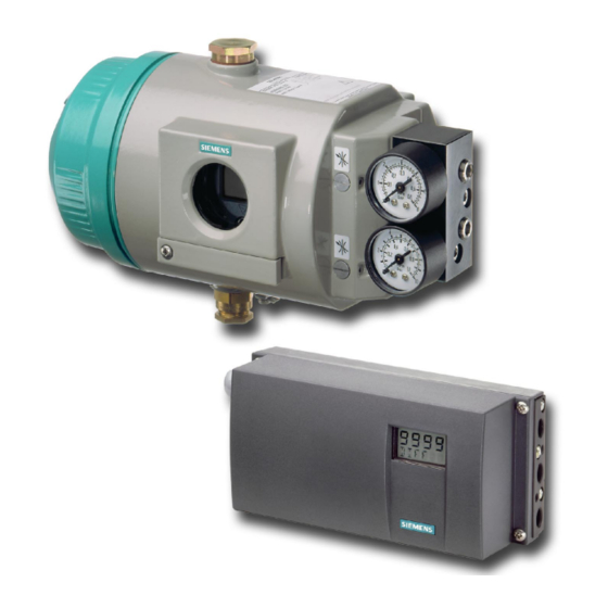
- Page 13 Introduction Actuator Positioner, single action in metal housing Lantern Manometer block, single action Valve Figure 1-1 Positioner mounted on linear actuator (single action) Positioner double action in plastic housing Rotary actuator Manometer block, double action Figure 1-2 Positioner mounted on rotary actuator (double action) SIPART PS2 Manual A5E00074631-01...
- Page 14 Introduction Actuator Positioner, single action in metal housing Lantern Manometer block, single action Figure 1-3 Explosion proof positioner mounted on linear actuator (single action) Positioner double action in plastic housing Rotary actuator Manometer block, double action Figure 1-4 Explosion proof positioner mounted on rotary actuator (double action) SIPART PS2 Manual A5E00074631-01...
-
Page 15: Design And Method Of Operation
Design and Functional Principle Design and Method of Operation The following chapter describes the mechanical and electrical design, the instrument components and method of operation of the positioner. Overview The electropneumatic positioner forms a control system in connection Introduction with an actuator. The current position of the actuator is detected by a servo potentiometer and fed back as actual value x. -
Page 16: Instrument Components
Design and Functional Principle puts respond even when the power supply fails or the electronics are defective. The actuator can also be blocked or driven to its final positions depen- ding on the configuration for example by an external event via a digital input (DI2) on the alarm module. -
Page 17: Motherboard
Design and Functional Principle - - - - Input: Supply air Transmission ratio selector Output: Actuating pressure Y1 (only possible with positioner open) Display Adjusting wheel slip clutch Output: Actuating pressure Y2 Terminals standard controller Operating keys Terminals options modules Restrictor Y1 Safety catch Restrictor Y2... -
Page 18: Pneumatic Connections
Design and Functional Principle 2.2.3 Pneumatic Connections The pneumatic connections are on the right hand side of the positioner (figure 2-3 and figure 2-4). Actuating pressure Y1 in single- - and double- -acting actuators Feedback shaft Supply air P Actuating pressure Y2 in double- -acting actuators Exhaust air output E with silencer on the bottom of the instrument Figure 2-3 Pneumatic connection in normal version... - Page 19 Design and Functional Principle The exhaust air output E can be provided for supplying dry instrument air to the tapping chamber and spring chamber to prevent corrosion. Figure 2-5, page 20 shows the pneumatic connection variants for the different actuator types, the positioning action and the safety position after power failure.
- Page 20 Design and Functional Principle Positioning Safety position after power failure Actuator type pressure electrical pneumatic Connection In rotary actuators the direction of rotation counterclockwise looking onto the actuating shaft of Closed Closed the valve is usually defined as ”Open”. Open Closed Open Open...
-
Page 21: Mounting Kit
Design and Functional Principle 2.2.4 Mounting Kit The positioner can be mounted on almost all actuators with the appro- priate mounting kit. 2.2.5 Purge air switching (not in the explosion proof version) The purge air switch is accessible above the pneumatic terminal strip with the housing open (figure 2-6). -
Page 22: Method Of Operation
Design and Functional Principle Method of Operation The electropneumatic positioner SIPART PS2 forms a control circuit with the pneumatic actuator in which the actual value x is the position of the actuator bar in linear actuators or the position of the actuator shaft in rotary actuators and the command variable w is the actuating current of a controller or a manual control station of 4 to 20 mA. - Page 23 Design and Functional Principle NOTE The exhaust air valve is always open when there is no current. Figure 2-8 Method of operation five--point switch SIPART PS2 Manual A5E00074631-01...
- Page 24 Design and Functional Principle HART Supply air Zuluft Exhaust air Abluft +24 V +5 V Micro- controller Exhaust Abluft stroke stroke 1 Motherboard with microcontroller and input circuit 2 Control panel with LC-display and momentary action switch 3 Piezo--valve unit, always built--in 4 Valve unit with double action positioner always built--in 5 Iy-module for positioner SIPART PS2 6 Alarm module for three alarm outputs and one digital input...
-
Page 25: State As Supplied
Design and Functional Principle State as supplied There are no mechanical mounting accessories on the controller in the state as supplied These must be ordered and installed according to the “operating instructions” depending on the application. The respective connections for single or double action versions are pre- pared at the factory as ordered. - Page 26 Design and Functional Principle Alarm module Insert the alarm module (4) in the top pcb rails of the container, establish the electrical connection with the enclosed ribbon cable (5). SIA-module (Slot Initiator Alarm module) Proceed as follows for installation: Remove all the electrical connections from the basic electronics (2).
- Page 27 Design and Functional Principle 15. Drive the actuator to the second desired mechanical position. 16. Adjust the bottom actuating disc (for output terminals 51--52) by hand until the output level changes. NOTE If you turn the actuating disc beyond the switching point up to the next switching point, you can set a high-low or a low-high change.
-
Page 28: Options Modules In Explosion Proof Version
Design and Functional Principle 2.5.2 Options modules in explosion proof version The options modules are protected and mechanically fixed by a module cover ((1), see figure 2-11, page 29). NOTE The housing must be opened to install the options modules. The degree of protection IP65/NEMA4x is not guaranteed as long as the positioner is open. -
Page 29: Hart-Function
Design and Functional Principle 13.1 13.1 Module cover Transmission ratio selector Fixing screws Adjusting wheel for slipping clutc PA module Housing module with ribbon cable Screw- -on cover Alarm module with ribbon cable Safety catch Ribbon cable for alarm module Rack Ribbon cable for J module... -
Page 30: Alarm Module
Design and Functional Principle The SPART PS2 is integrated in the following parameterization tools: - Handheld communicatorR - PDM (Process Device Manager) - AMS (Asset Management System; update in preparation) - Cornerstone NOTE Operation on the positioner has priority over the settings via the HART inetrface. -
Page 31: Jy-Module
Design and Functional Principle Installation The alarm module is pushed in underneath the motherboard into the module rack up to the stop and connected by the enclosed 8-wire rib- bon cable (5) to the motherboard (see figure 2-10, page 27). 2.5.5 Jy-module Function With the J... -
Page 32: Accessories
Design and Functional Principle 2.5.7 Accessories Figure 2-12 Manometer block (left for single--acting, right for double--acting actuators) Manometer block The manometer block for single--acting actuator contains two manometers which are screwed to the lateral pneumatic connection of the positioner with O--rings. The values for the input pressure (supply air PZ) and output pressure (actuating pressure Y1) are displayed. -
Page 33: Preparing For Operation
Preparing for Operation Preparing for Operation This chapter describes all the preparations necessary for operating the positioner. Instrument identification (type key) The order number of the positioner is printed on the rating plate and on the packaging. Compare this with the order number in chapter 7.1, page 105. - Page 34 Preparing for Operation 79,5 G 1/4 or 20,5 1/4” NPT 2xM6 29,5 58,75 Thread depth 5.5 Figure 3-2 Dimensional drawing terminal strip for plastic housing 50 x 4 x M6 9 deep M8, 9 deep All air connections 11,2 G 1/4 or 1/4” NPT M20 x 1.5 or NPT-adapter 14,5 38,5...
-
Page 35: Assembly
Preparing for Operation All air connections ”NPT M8, 14 deep (4x) M6, 11 deep (4x) M6, 8 deep (2x) 87,2 M20, M25 or 14,3 25,7 ”NPT (2x) 129,5 Connection 238/Y2 only in double action version 235,3 Æ 8 h9 Figure 3-4 Dimensional drawing for positioner with metal housing in explosion proof version 6DR5xx5 Assembly... -
Page 36: Instructions For Using Positioners In A Wet Environment
Preparing for Operation NOTE The positioner will be equipped at the factory and delivered complete with the necessary options at the customer’s request. Options modules may only be retrofitted by our service technicians. The positioner must be assembled – especially in a moist environment –... - Page 37 Preparing for Operation Figure 3-5 Favorable and unfavorable installation positions If conditions oblige you to operate the positioner in a unfavorable installation position, you can take additional precautionary measures to prevent penetration by water. NOTE Never clean the positioner with a high pressure water jet because the IP65 degree of protection is inadequate protection for this.
-
Page 38: Instructions For Using Positioners Which Are Exposed To Great Accelerations Or Vibrations
Preparing for Operation - Mount the above mentioned plastic hose on the screw--type gland and check the good fit. - Fix the plastic hose with a cable strap to the fitting so that the opening faces downwards. - Make sure that the hose has no kinks and the exhaust air can flow out unhindered. -
Page 39: Mounting Kit "Linear Actuator" 6Dr4004-8V And 6Dr4004-8L
Preparing for Operation 3.3.3 Mounting kit ”linear actuator” 6DR4004-8V and 6DR4004-8L The scope of delivery of the mounting kit” linear actuator IEC 534 (3 mm to 35 mm)” are contained (ser. no. see figure 3-6, page 41): Ser. no. pieces Designation Note NAMUR mounting kit bracket... - Page 40 Preparing for Operation Fit the mounting bracket (1) with two hexagon head screws (9), lock washer (10) and flat washer (11) on the rear of the positioner. Selection of the row of holes depends on the width of the actuator yoke.
- Page 41 Preparing for Operation Without explosion proof version Explosion proof version: Figure 3-6 Assembly procedure (linear actuator) SIPART PS2 Manual A5E00074631-01...
-
Page 42: Sipart Ps2 Manual
Preparing for Operation Mounting on yoke Mounting on yoke with plane surface with ledge Mounting on yoke with columns as required Figure 3-6 Assembly procedure (linear actuator) continued 3.3.5 Mounting kit ”Rotary actuator” 6DR4004-8D The scope of delivery of the mounting kit ”Rotary actuator” contains (ser. no. see figures 3-7 and 3-8): Ser. -
Page 43: Assembly Procedure (See Figure 3-7 And Figure 3-8)
Preparing for Operation 3.3.6 Assembly procedure (see figure 3-7 and figure 3-8) Attach VDI/VDE 3845 mounting console ((9), actuator--specific, scope of delivery actuator manufacturer) onto rear of positioner and secure using hexagon head screws (14) and lock washers (15). Adhere pointer (4.2) onto mounting console in the center of the centering hole. -
Page 44: A5E00074631-01
Preparing for Operation 0%20 40 60 80 100% Figure 3-7 Assembly procedure (rotary actuator) SIPART PS2 Manual A5E00074631-01... - Page 45 Preparing for Operation 0%20 40 60 80 100% Figure 3-8 Assembly procedure forexplosion proof version(rotary actuator) SIPART PS2 Manual A5E00074631-01...
- Page 46 Preparing for Operation CUT A - - B 14, 15 positioner 14, 15 G 1/4 rotary actuator 16, 17 10 Coupling wheel Feedback shaft Carrier Hexagon head screw M6 x 12 Multiple plate Lock washer S6 Scale Fillister head screw M6 x 12 Pointer mark Washer VDI/VDE 3845-mounting bracket...
- Page 47 Preparing for Operation fastening level Befestigungsebene Stellungsregler positioner +0,1 Schwenkantrieb rotary actuator F05-Lkr.- Figure 3-10 Attachment of rotary actuator, mounting console (scope of delivery actuator manufacturer), dimensions SIPART PS2 Manual A5E00074631-01...
-
Page 48: Electrical Connection
Preparing for Operation Electrical Connection NOTE Any necessary options modules must be installed before electrical connection (see chapter 2.5, page 25). N.B.: The transmission ratio selector can only be set when the positioner is open. Therefore check this setting before sealing the controller. -
Page 49: Connection Variants
Preparing for Operation Shield Figure 3-11 Base plate 3.4.1 Connection variants 3.4.1.1 Connection variant: not intrinsically safe The electrical connection of the positioner can be made in the following ways: 4 to 20 mA 6DR5010-xNxxx Positioner 6DR5020-xNxxx 6DR5011-xNxxx 6DR5110-xNxxx +3 V 6DR5120-xNxxx Digital inputs 1 6DR5111-xNxxx... -
Page 50: Connection Variant: Intrinsically Safe
Preparing for Operation 3.4.1.2 Connection variant: intrinsically safe NOTE Only certified intrinsically safe circuits may be connected as power supply, control and signal circuits. Non-hazardous Hazardous area zone 1 or zone 2 area 4 to 20 mA Positioner 6DR5010-xExxx 6DR5020-xExxx 6DR5011-xExxx +3 V Digital inputs 1... - Page 51 Preparing for Operation Non-hazardous Hazardous area zone 1 or zone 2 area Positioner 6DR5210-xExxx 4 to 20 mA 6DR5220-xExxx 6DR5211-xExxx Intrinsically safe power source +3 V Digital inputs 1 HART Communicator Figure 3-14 Two--wire connection standard controller 6DR52xx-xExxx Non-hazardous Hazardous area zone 1 or zone 2 area 18 to 30 V 6DR5210-xExxx...
-
Page 52: Connection Variant: Options In Positioner In Non--Intrinsically Safe And Explosion Proof Version
Preparing for Operation Split-range Figure 3-16 Series circuit of two positioners, e.g. split range (separate power supply) 3.4.1.3 Connection variant: Options in positioner in non- -intrinsically safe and explosion proof version Current output -module: 6DR4004-8J Figure 3-17 module 6DR4004-8J, non Ex SIPART PS2 Manual A5E00074631-01... - Page 53 Preparing for Operation Digital inputs and outputs Alarm module 6DR4004-8A +13 V ≥1 Digital input 2 +4.5 V +3 V +24 V Fault message +24 V Limit value A1 +24 V Limit value A2 Figure 3-18 Alarm module non Ex SIA module SIA module: 6DR4004-8G...
-
Page 54: Connection Variant: Options In The Positioner In Intrinsically Safe Version
Preparing for Operation 3.4.1.4 Connection variant: Options in the positioner in intrinsically safe version Current output Non--hazardous area Hazardous area zone 1 or zone 2 -module: 6DR4004-6J Intrinsically safe power sources Figure 3-20 -module 6DR4004-6J, Ex SIPART PS2 Manual A5E00074631-01... - Page 55 Preparing for Operation Digital inputs and outputs Alarm module 6DR4004-6A Digital ≥1 input 2 +3 V +8.2 V Intrinsically safe Fault Switching message amplifier to EN 50227 +8.2 V Limit value A1 +8.2 V Limit value A2 Non--hazardous area Hazardous area zone 1 or zone 2 Figure 3-21 Alarm module 6DR4004-6A, Ex Current output...
-
Page 56: Pneumatic Connection
Preparing for Operation Pneumatic Connection WARNING For reasons of safety, the pneumatic power may only be supplied after assembly when the positioner is switched to operating level P manual operation with electrical signal applied (as--delivered state, see figure 4-4, page 76). NOTE Note the air quality! Oil--free industrial air, solid content <... -
Page 57: Commissioning
Preparing for Operation Commissioning Due to the wide range of application possibilities the positioner must be adapted (initialized) to the respective actuator individually after assem- bly. This initialization can be effected in three different ways: - Automatic initialization Initialization takes place automatically Hereby the positioner deter- mines the direction of action, the displacement path and the angle of rotation, the adjusting times of the actuator one after the other and adapts the control parameters to the dynamic behavior of the actua-... -
Page 58: Preparations For Linear Actuators
Preparing for Operation 3.6.1 Preparations for linear actuators Assemble the positioner with the appropriate mounting kit (see chapter 3.3.3, page 39). NOTE Particularly important is the position of the gear transmission switch (8, figure 2-1, page 16) in the positioner: Stroke Lever Position of the gear transmission... -
Page 59: Automatic Initialization Of Linear Actuator
Preparing for Operation 3.6.2 Automatic initialization of linear actuator If you can move the actuator correctly, leave it standing in a central po- sition and start automatic initialization: Press the operation mode key for longer than 5 s. This brings you to the Configuration operating mode. - Page 60 Preparing for Operation Start initialization by pressing the key for longer than 5 s. Display: During the initialization phase ”RUN1” to ”RUN5” appear one after an- other in the bottom display (see also structograms figures 3-24, page 68 to figure 3-27, page 71). NOTE The initialization process may last up to 15 minutes depending on the actuator.
-
Page 61: Manual Initialization Of Linear Actuator
Preparing for Operation 3.6.3 Manual initialization of linear actuator The positioner can be initialized with this function without the actuator being driven hard against the limit stop. The start and end positions of the displacement path are set manually. The other initialization steps (optimization of the control parameters) run automatically as in automa- tic initialization. - Page 62 Preparing for Operation Switch on to the following display by pressing the operation mode key twice: Start initialization by pressing the increment key for longer than 5 s. Display: After 5 s the display changes to: (The display of the potentiometer setting is shown here and below as an example only).
- Page 63 Preparing for Operation If step 7 was successful, the following display appears: Now move the actuator to the position which you want to define as the second end position with the increment and decre- ment key. Then press the operation mode key .
-
Page 64: Preparations For Rotary Actuator
Preparing for Operation 3.6.4 Preparations for rotary actuator NOTE Very important: Switch the transmission ratio selector in the positioner (8, figure 2-1, page 16) to position 90° (normal angle for rotary actuator). Mount the positioner with the appropriate mounting kit (see chapter 3.3.5, page 42). - Page 65 Preparing for Operation Set the parameter with the -key to ”turn” Display: Switch to the second parameter by pressing the operation mode briefly. This has set automatically to 90°. Display: Switch on to the following display with the operation mode key Start initialization by pressing the key for longer than 5 s.
-
Page 66: Manual Initialization Of Rotary Actuators
Preparing for Operation The following display appears after pressing the operation mode key briefly: To exit the Configuration mode, press the operation mode key longer than 5 s. The software version is displayed after about 5 s. The instrument is in manual operation after releasing the operation mode key. -
Page 67: Automatic Initialization (Structograms)
Preparing for Operation Switch to the second parameter by pressing the operation mode briefly. Display: NOTE Make sure that the transmission ratio selector is in position 90 °! Switch on to the following display by pressing the operation mode twice: The following steps are identical with the steps 6) to 9) for initiali- zation of linear actuators. - Page 68 Preparing for Operation Figure 3-24 Automatic initialization, part 1 SIPART PS2 Manual A5E00074631-01...
- Page 69 Preparing for Operation Figure 3-25 Automatic initialization part 2 (in rotary actuators) SIPART PS2 Manual A5E00074631-01...
- Page 70 Preparing for Operation Figure 3-26 Automatic initialization part 2 (in rotary actuators) SIPART PS2 Manual A5E00074631-01...
- Page 71 Preparing for Operation Figure 3-27 Automatic initialization, part 3 SIPART PS2 Manual A5E00074631-01...
-
Page 72: Copying Initialization Data (Positioner Exchange)
Preparing for Operation Copying initialization data (positioner exchange) With this function you have the possibility of starting up a positioner without running the initialization routine. This allows for example a posi- tioner to be changed on a running system in which automatic or manual initialization cannot be performed without disturbing the process. -
Page 73: Operation
Operation Operation The following chapter describes the operation of the positioner. Display The LC display has two lines whereby the lines have different segmentation. The elements of the top line consist of 7, those of the bottom line of 14 segments. The display depends on the selected operating mode (see chapter 4.3, page 76) NOTE If the positioner is operated in ranges with temperatures below --10 °C... - Page 74 Operation Figure 4-1 Meaning of the various display options NOTE The degree of protection IP 65/NEMA4x is not guaranteed as long as the positioner is open. SIPART PS2 Manual A5E00074631-01...
- Page 75 Operation Display Operation mode key Decrement key Increment key Figure 4-2 Display and input keys of the positioner Explanations of the input keys - The operation mode key (manual key) serves to switch over the operating mode and pass on parameters. NOTE By pressing and holding the operation mode key and additionally pressing the decrement key, you can select the parameters in reverse...
-
Page 76: Operating Modes
Operation Operating modes The positioner can be operated in five operating modes. P-manual mode (ex--factory state) Configuration and initialization Manual mode (MAN) Automatic (AUT) Diagnostic display Figure 4-4 gives you an overview of the possible operating modes and the change between them. Figure 4-4 Change between the operating modes SIPART PS2 Manual... - Page 77 Operation P-manual mode The display of the positioner shows you the current potentiometer (ex- -factory state) setting in the top line and ”NOINIT” flashes in the second line. You can move the actuator with the decrement and increment key . In order to adapt the positioner to your actuator, you have to change to the Configuration menu.
-
Page 78: Parameters
Operation Manual mode In this operating mode you can move the actuator with the decrement (MAN) ) and increment keys ( ) and the current position is held regardless of the setpoint current and any leakages. NOTE You can move the actuator quickly by pressing the other direction key additionally whilst keeping the direction key selected first pressed. - Page 79 Operation Display Factory setting Customer setting Parameter name Function Parameter values Unit turn (part-turn actuator) Type of actuator 1.YFCT WAY (linear actuator) LWAY (linear actuator without sine correction) ncSt (part-turn actuator with NCS) -ncSt (ditto, inv. direction of action Rated angle of rotation of feedback 90°...
- Page 80 Operation 1.YFCT Positioning actuator type Selection of used actuator: Linear actuator (WAY), rotary actuator (turn). The unlinearity which exists in linear actuators due to the conversion of linear movement to rotational movement is compensated by the positioner when 1.YFCT = WAY is selected. If an external, linear potentiometer is used for displacement measuring, “1.YFCT”...
- Page 81 Operation NOTE The specification “YWAY” must match the mechanical lever arm trans- mission. The carrier must be set to the value of the actuator stroke, if this is not scaled to the next highest scaled value. 4.INITA Automatic initialization (see chapter 3.6, page 57) By selecting “Strt”...
- Page 82 Operation y = x 100 % Positioner 1 6.SDIR = FALL Total setting range Positioner 2 6.SDIR = riSE 100 %- -SPRE 100 %- -SPRA SPRA SPRE 100 % [0 % to 100 %] Positioner 1 Positioner 2 Setting range 1 Setting range 2 Figure 4-7 Example: Split range-operation with two positioners...
- Page 83 Operation - inverse equal percentage 1 : 33 (12.SFCT = n1 --33) - inverse equal percentage 1 : 50 (12.SFCT = n1 --50) Figure 4-8 Setpoint characteristic, manipulated variable standardization and tight sealing function SIPART PS2 Manual A5E00074631-01...
- Page 84 Operation 13.SL0 to 33.SL20 Setpoint vertex points (see figure 4-8, page 83) A flow parameter can be assigned to the respective setpoint vertex va- lue at an interval of 5%. These points lead to a polygon chain with 20 straight lines which therefore represents a projection of the valve cha- racteristic.
- Page 85 Operation YNRM = MPOS or YNRM = FLOW Presetting: YA = 0% and YE = 100% Input current (setpoint) 7.2mA 10.4mA 13.6mA 16.8mA 20mA X display W display 100% Mechan. Stroke (actual value) 16mm 32mm 48mm 64mm 80mm YA = 0% YE = 100% Example: YNRM = MPOS with YA = 10 % and YE = 80 %...
- Page 86 Operation 40.YCDO Value for sealing bottom When the sealing function bottom (see parameter“39.YCLS”is activa- ted, it can be set below which setpoint the bottom sealing is activated with this parameter. 41.YCUP Value for sealing top When the sealing function top (see parameter“39.YCLS”is activated, it can be set above which setpoint the top sealing is activated with this parameter.
- Page 87 Operation 44.AFCT Alarm function The actuator can report the exceeding (max.) or dropping below (min) of a specified stroke or angle of rotation. The response of the alarms (limit contacts) is related to the MPOS-scaling (see figure 4-9, page 85). The alarms are reported by the alarm module (order no. 6DR4004-6A or -8A).
- Page 88 Operation 50. STRK Limit value for monitoring the way integral A limit value for the way integral can be set here. If the way integral exceeds the limit value, the fault message output (optional) is activated. This function enables a preventive maintenance of the fitting, see also chapter 4.5 “Diagnostics”, page 90.
- Page 89 Operation NOTE But the monitors of the bottom and top hard stop do not only react to valve errors. Adjustment of the position feedback is also detected as an error if the tolerance values are exceeded as a result. 54. DEBA Limit value for monitoring the dead zone adaptation The automatic adaptation of the dead zone can be monitored with this value (%).
-
Page 90: Diagnosis
Operation Diagnosis 4.5.1 Diagnostic display You go to the diagnostic display from automatic or manual operation by simultaneously pressing all three keys for at least two seconds. Table 3-1, page 91 shows an overview of the displayable values. In the third column the corresponding English term from which the abbrevia- tion is derived is shown next to the German meaning unless this is self explanatory. -
Page 91: Meaning Of The Diagnostic Values
Operation Abbrevia- Meaning Displayable Unit Rest tion values poss. Number of operating hours in Temperature range 7 0 to 4.29E9 Hours Number of operating hours in Temperature range 8 0 to 4.29E9 Hours Number of operating hours in Temperature range 9 0 to 4.29E9 Hours VENT1... - Page 92 Operation 7 WAY Determined actuating way This value indicates the actuating way determined during initialization according to the display at the end of an initialization. Prerequisite in linear actuator: Specification of the lever arm with the parameter “3.YWAY”. 8 TUP Travel time up 9 TDOWN travel time down...
-
Page 93: Online-Diagnosis
Operation 19 TEMP Current temperature Current temperature in the positioner housing The sensor is on the electronics board. 20 TMIN Minimum temperature (drag pointer) 21 TMAX Maximum temperature (drag pointer) The minimum and maximum temperature inside the housing is determi- ned and stored continuously in a kind of drag pointer. - Page 94 Operation Table 3-2, page 94 shows which events can activate the fault message output, how the parameters must be set for this event to be monitored, when the fault message disappears again and where the possible causes of the fault lie. In automatic and manual operation response of the fault message output on the display shows which is the fault message trigger.
- Page 95 Operation Explanations of column “Error codes”: Monitoring of control error In automatic operation the error between setpoint and actual value is monitored continuously. The fault message is activated with unchanged control error according to the setting of the parameters 48. TIM, moni- toring time for setting the fault messages and 49 LIM, response thres- hold of the fault message.
- Page 96 Operation The fault message remains activated until either a subsequent monitoring remains within the tolerance or a new initialization is performed. The deactivation of the monitoring (“52. ZERO”=OFF) also clears any existing fault message. This monitoring function supplies no useful results when the stops have not been determined automatically in initialization but the limits set manually (manual initialization“5.INITM”).
- Page 97 Operation Figure 4-10 Configuration block diagram SIPART PS2 Manual A5E00074631-01...
- Page 98 Operation SIPART PS2 Manual A5E00074631-01...
-
Page 99: Service And Maintenance
Care and Maintenance Service and Maintenance The positioner is largely maintenance--free. The positioners are fitted with filters in the pneumatic connections as protection against coarse particles of dirt. If the pneumatic energy supply contains particles of dirt, the filters may clog and impair the function of the positioner. In this case the filters can be cleaned as follows. - Page 100 Care and Maintenance 8. Replace the cover and screw it tight. 9. Re--connect the pipes and supply pneumatic energy. DANGER Electrostatic charging must be prevented in hazardous areas. These could be caused by example when cleaning the positioner in plastic housing with a dry cloth.
-
Page 101: Technical Data
Technical Data General data for basic device 6DR5xxx-xx Travel range (linear actuators) 3 to 130 mm (angle of feedback Pneumatic data shaft 16 to 90°) Supply (inlet air) Angle or rotation (part-turn 30 to 100° • Pressure 1.4 to 7 bar: sufficiently larger actuators) than max. - Page 102 Technical data See "General data", page 101 Binary input BI1 Weight, basic device SIPART PS2 • Plastic casing Approx. 0.9 kg Explosion protection to EEx n EEx ia/ib • Metal casing Approx. 1.3 kg EN 50 014 and EN 50 020 II 3G Ex nV II T4 II G EEx ib II C T6 Dimensions...
- Page 103 Technical data SIA module Option modules Limit monitor with slot-type initia- 6DR4004-8G or Electrical data Without Ex pro- With Ex protection tection tors and alarm output 6DR4004-6G (only for 6DR5...) Connection Two-wire system to DIN 19 234 Explosion protection to –...
- Page 104 Technical Data SIPART PS2 Manual A5E00074631-01...
-
Page 105: Scope Of Delivery
Scope of deliver Scope of Delivery The positioner and its options modules are delivered as separate units and in different versions. positioners and options modules for operation in hazardous areas and non--hazardous areas are available. These ver- sions are identified respectively by a special rating plate. WARNING In the combination of components it must be ensured that only positio- ners and options modules are combined which are approved for the... -
Page 106: Scope Of Delivery Of Options
Scope of delivery Scope of delivery of options Option Order number SIA module non Ex 6DR4004-8G SIA module Ex (CENELEC / FM) 6DR4004-6G Alarm module non Ex 6DR4004-8A Alarm module Ex (PTB) 6DR4004-6A Alarm module Ex (FM) 6DR4004-7A -module non Ex 6DR4004-8J -module Ex (PTB) 6DR4004-6J... -
Page 107: Appendix
Appendix Index Accessories, 32 Electrical connection, 17, 48 Alarm function, 87 intrinsically safe, without PROFIBUS PA, 50 Alarm module, 30 not intrinsically safe, 49 Ex, 55 non Ex, 53 Application positioner in a wet environment, 36 Filters, Cleaning the ~, 99 under great accelerations and vibrations, 38 Firmware version, 75 Assembly, 35... - Page 108 Appendix Linear actuator, 13, 14 Rotary actuator, 13, 14, 46, 47 automatic initialization, 59 Automatic initialization, 64 manual initialization, 61 manual initialization, 66 preparation, 58 preparation, 64 Maintenance, 99 Safety information, Meaning of ~, 6 Manometer block, 32 Scope of Delivery, 105 Manual mode Series circuit, of two positioners, 52 Changing the operating mode, 78...
-
Page 109: A2 Literature And Catalog
Appendix Literature and Catalog Title Issued by Order Number SIMATIC NET Siemens AG E86060--K6710--A101--A9--7600 Industrial Communication and Field Devices Catalog IK PI SIMATIC Siemens AG E86060--K4678--A111--A3--7600 SIMATIC PCS 7 Process Control System Catalog ST PCS 7 Conformity EC Type Examination Certificate... - Page 110 Appendix EC Declaration of Conformity SIPART PS2 Manual A5E00074631- -01...
- Page 112 1P A5E00074631 Siemens AG Bereich Prozessinstrumentierung und -analytik Geschäftsgebiet A&D PI E Siemens AG 2001 Subject to change without prior notice D-76181 Karlsruhe Order No. A5E00074631 Siemens Aktiengesellschaft Printed in the France AG 0201 MG 112 GB...