Advertisement
Quick Links
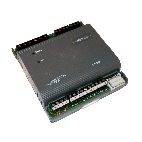
TC-9102 Fan Coil Unit Controller
Introduction
• Model Types
• Controller Functions
• Output Types
• Fan Output Types
Installation
• Mounting
• Wiring
• Jumper and Switch Selections
• Startup
• Commissioning
Specifications & Technical Data
• Factory-Set Parameters
• Parameters for Supervisory System
• Ordering Codes
© 1998 Johnson Controls, Inc.
Order No. MN-9100-2117
System 91 Manual
TC-9102
Technical Bulletin
Issue Date 0698
Page 3
4
5
10
12
15
15
16
22
23
23
25
26
27
28
1
Advertisement

Related Manuals for Johnson Controls METASYS TC-9102 Series


Summary of Contents for Johnson Controls METASYS TC-9102 Series
- Page 1 • Fan Output Types Installation • Mounting • Wiring • Jumper and Switch Selections • Startup • Commissioning Specifications & Technical Data • Factory-Set Parameters • Parameters for Supervisory System • Ordering Codes © 1998 Johnson Controls, Inc. Order No. MN-9100-2117...
- Page 2 Technical Bulletin—TC-9102...
- Page 3 Introduction The TC-9102 series of microprocessor-based controllers is designed for the control of Fan Coil Units (FCUs) with heating and cooling, and a single-speed, 3-speed or variable-speed fan. The controller can regulate water valves, one or 2-stage electric heating, or a cooling unit where the compressor has its own short cycle protection.
- Page 4 2333 Figure 3: TM-9180 Room Command Module The TC-9102 Controller is available in several model types according to Model Types the type of outputs and the range of the integrated or remote set point input. Refer to Ordering Codes at the end of this bulletin for details. Technical Bulletin—TC-9102...
- Page 5 The controller can be connected to a Room Command Module, from Controller which it receives the room temperature, the remote set point and other Functions override signals. The TM-9180 intelligent Room Command Module provides these signals via a serial bus connection to the controller. The other Room Command Modules (TM-9150/9160/9170) provide the signals as individually connected physical inputs to the controller.
- Page 6 Standalone The controller operates in standalone mode when it is not connected to a Mode supervisory system via the communications bus nor to a TM-9180 Room Command Module. In standalone mode the controller may operate in one of three control modes: •...
- Page 7 Controller Set The set point in all control modes may be modified from the integrated Points set point adjuster or from the remote set point dial/control panel on the Room Command Module, according to the controller model type. The controller models with a remote set point of 12-28°C require that a Room Command Module or an external potentiometer is connected to give the set point.
- Page 8 Alternate Mode When pressed for about one second, the occupancy button on the Room Command Module changes the mode of operation of the controller to the “Alternate Mode” or back to the normal “Control Mode” as shown in Table 2. The “COMFORT (T)” alternate mode is active only for a period of one hour, after which the controller reverts to the normal control mode.
- Page 9 Winter/Summer When the controller is connected to a supervisory system, the winter Compensation and/or summer compensation modes may be enabled. The supervisory system must be programmed to set the outdoor air temperature via the communications bus on a periodic basis. After a power interruption the winter and summer compensation modes are temporarily disabled until a new outdoor air temperature value is received.
- Page 10 Auto-dial When the controller is connected to a remote N2 Bus and supervised by a Feature Metasys N2 Dialer (NU-NDM101-0) which is linked to a Metasys network by a telephone line, the following alarm conditions in the controller will initiate the automatic dial feature: •...
- Page 11 PAT - Position The PAT output is a pair of triacs which are switched on to open and Adjust Type close an incrementally driven heating or cooling valve. The duration of switching is directly proportional to the change in the controller output and related to the full stroke time of the valve such that a 100% change will completely open or close the valve.
- Page 12 Fan Output Types Fan On/Off The output is a normally open relay contact which closes when the fan is required to run. Terminals are provided to connect the fan supply voltage to the controller in order to facilitate the wiring to the fan motor. The fan supply voltage is not used within the controller.
- Page 13 0 to 10 VDC The output is a control signal for driving a fan speed controller with an Control Signal opto-isolated 0 to 10 VDC input. As the output voltage increases, the fan speed controller must increase the speed of the fan from the minimum speed of the fan motor to its maximum speed.
- Page 14 Technical Bulletin—TC-9102...
-
Page 15: Installation
Users should ensure that all Johnson Controls' products are used safely and without risk to health or property. For surface mounting, slide the two mounting brackets into the slots at Mounting opposite corners of the controller base behind the terminals. - Page 16 Note: A minimum of 25 mm of space is required above and below the controller for the removal of separable terminals. Technical Bulletin—TC-9102...
- Page 17 Before connecting or disconnecting any wires, ensure that all power Wiring supplies have been switched off and all wires are potential-free to prevent equipment damage and avoid electrical shock. Terminations are made on the terminal blocks, at the top and bottom of the controller, which accept up to 1.5mm wires.
- Page 18 Analog 0 -10 VDC When using multistranded wire, crimp a metal sleeve over the exposed PAT 24 VAC conductors before inserting into terminals 60...71. External supply for fan 230 VAC L = Live 24 VAC Isolate before servicing. 24 VAC DAT 24 VAC Common Supply...
- Page 19 Analog 0 -10 VDC When using multistranded wire, crimp a metal sleeve over the exposed PAT 24 VAC conductors before inserting into terminals 60...71. External supply for fan 3-Speed 230 VAC L = Live 24 VAC 24 VAC DAT 24 VAC Isolate before servicing.
- Page 20 Analog 0 -10 VDC PAT 24 VAC 24 VAC 24 VAC Supply Common DAT 24 VAC Ground ON-OFF 0 -10 VDC (2 stages) Fan Speed Control 24 VAC See Note 1 31 30 Cooling Output Power Supply Heating Output See Note 2 System 91 N2 Digital Inputs Analog Inputs...
- Page 21 Figure 16: TC-9102 Controller Wiring - 0 to 10 VDC Fan Control TM-9150/TM-9160 TC-9102 Controller Room Command Module 3-Speed Fan Override* Remote Set Point** Common 21/24 Internal NTC Sensor Connections Mode LED Occupancy Button Max. 50 m tc2wwntc (Min. 0.8 mm diameter wire) *Only for modules with 3-speed fan override (see ordering codes).
- Page 22 Figure 18: TC-9102 Controller Wiring to Room Command Module with Unit Mounted NTC Sensor Technical Bulletin—TC-9102...
- Page 23 TC-9102 TM-9180 Room Controller Command Module Voltage Supply Common 21/24 Data clock Transmit/Receive Max. 50 m tc2wtm80 (Min. 0.8 mm diameter wire) Figure 19: TC-9102 Controller Wiring to TM-9180 Room Command Module TC-9102 TM-9180 Room Controller Command Module Voltage Supply 21/24 Common NTC Sensor...
- Page 24 Jumper and CAUTION: Connections to the on/off or 3-speed fan control Switch terminals may carry up to 250 VAC. Isolate live and Selections neutral supply lines (double-pole switch) before servicing. To reach the jumpers and switches, open the controller by gripping the cover with thumb and finger on both sides above center and pull the cover off using the lower edge as a hinge.
- Page 25 Integral Time Jumper (Blue) Zone 1 Jumper (Black) Gain Jumper (Red) Zone 2 Jumper (Black) Factory Settings (4 spare jumpers packed with controller) Power Receive/ Transmit Address Switches 1 2 3 tc2jmpsw 1 2 3 Jumpers for TM-9180 Module with LCD Display 1 2 3 4 5 6 Address Switches 1 2 3...
- Page 26 Technical Bulletin—TC-9102...
-
Page 27: Specifications & Technical Data
Specifications & Technical Data Supply Voltage 24 VAC, +15% to -10%, 50-60 Hz. 3 VA for controller and room command module. Power Consumption (Add power consumption of connected actuating devices.) Ambient Operating 0° to 50°C Conditions 10 to 90% RH noncondensing Ambient Storage -20°... -
Page 28: Factory-Set Parameters
Factory-Set Parameters Table 3: Factory-Set Parameters Comfort Set Point Heating 20°C +/-3 K Remote Set Point. See Note 2. -1 K 12-28°C Remote Set Point Comfort Set Point Cooling 22°C +/-3 K Remote Set Point. See Note 2. +1 K 12-28°C Remote Set Point Prop. - Page 29 The following table lists the parameters which are available for Parameters for monitoring by Metasys supervisory systems. For details of configuration Supervisory procedures and override possibilities, refer to the technical documentation System of the system which is to be used. Table 4: Supervisory System Parameters Parameter Description Units...
- Page 30 Ordering Codes Table 5: TC-9102 Controller Ordering Codes Ordering Code Hardware Outputs Set Point Configuration Range Code (used in EuroPRO) TC-91a2-b220 TC-91x2-x220 2 x 0 to 10 VDC 0 to 10 VDC Fan Control 12 -28°C TC-91a2-b225 TC-91x2-x220 2 x 0 to 10 VDC 0 to 10 VDC Fan Control +/-3 K TC-91a2-b440...
- Page 31 Table 6: Room Command Module Ordering Codes Ordering Code Description TM-9150-0000 Occupancy Button NTC Sensor w/o S.P. dial TM-9160-0000 Occupancy Button NTC Sensor 12-28°C TM-9160-0005 Occupancy Button NTC Sensor +/- 3 K TM-9160-0002 Occupancy Button NTC Sensor 12-28°C 3-Speed Fan Override TM-9160-0007 Occupancy Button NTC Sensor...
- Page 32 Technical Bulletin—TC-9102...
- Page 33 Technical Bulletin—TC-9102...
- Page 34 Notes Johnson Controls, Inc. System 91 Manual Westendhof 8 TC-9102 Technical Bulletin 45143 Essen Rev. Level 0698 Germany Printed in Germany Technical Bulletin—TC-9102...