
Related Manuals for Sony DVCAM DSR-1500


Summary of Contents for Sony DVCAM DSR-1500
- Page 1 3-204-974-12(1) Digital Videocassette Recorder Operating Instructions Before operating the unit, please read this manual thoroughly and retain it for future reference. DSR-1500/1500P © 2000 Sony Corporation...
- Page 2 Owner’s Record The model and serial numbers are located at the bottom. Record these numbers in the spaces provided below. Refer to them whenever you call upon your Sony dealer regarding this product. Model No. Serial No. WARNING To prevent fire or shock hazard, do not expose the unit to rain or moisture.
-
Page 3: Table Of Contents
Table of Contents Chapter 1 Overview Chapter 2 Recording and Playback Chapter 3 Convenient Functions for Editing Operation Features...5 DVCAM Format ... 5 Variety of Interfaces... 6 Compact Size ... 6 Facilities for High-Efficiency Editing... 6 Other Features ... 7 Optional Accessories... - Page 4 Chapter 4 Menu Settings Chapter 5 Connections and Settings Chapter 6 Maintenance and Troubleshooting Appendixes Table of Contents Menu Organization ...55 Menu Contents...58 Setup Menu ... 58 Auto Mode (AUTO FUNCTION) Execution Menu... 71 Changing Menu Settings ...72 Buttons Used to Change Settings... 72 Changing the Settings of Basic Items ...
-
Page 5: Features
The following are the principal features of the unit. DVCAM Format DVCAM is a professional -inch digital recording format developed by Sony from the consumer DV component digital format. High picture quality and high stability Video signals are separated into color difference signals... -
Page 6: Variety Of Interfaces
DSBK-1501 board, SDTI (QSDI)-format video, audio and time code signals can be transferred between the unit and the Sony EditStation at normal speed. When this unit is connected to another DVCAM VCR, it is possible to copy compressed signals between the two VCRs. -
Page 7: Other Features
75-ohm termination. Closed caption compatibility Whether or not to include closed captions in a recording can be determined with menu items (for DSR-1500 only). Optional Accessories DSBK-1501 Digital Input/Output Board This interface enables digital video and audio signals in the... -
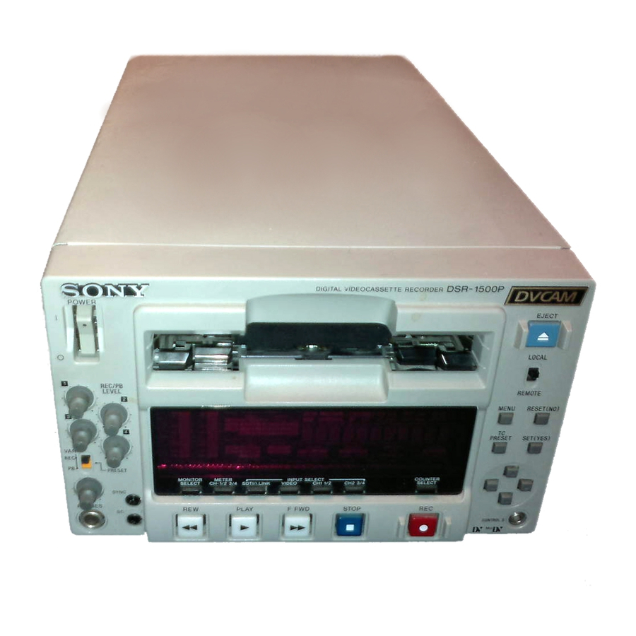
Page 8: Location And Function Of Parts
Location and Function of Parts Front Panel a POWER switch b Audio level meters c PHONES connector and control knob d SC control e SYNC control A Audio input/output level control section (see page 11) B Video/audio input setting section (see page 11) Location and Function of Parts f Cassette compartment POWER... - Page 9 a POWER switch Press the “ ” side to power on the unit. This causes the audio level meters and the display section to light. To power off the unit, press the “ ” side of the switch. b Audio level meters These two meters indicate the recording audio levels during recording or EE mode* and the playback audio levels during playback.
- Page 10 i MONITOR SELECT button Use this button and the METER CH-1/2 3/4 button to select the audio channels: • for level indications on the audio level meters • for audio output via the PHONES connector on the front panel • for audio output via the MONITOR connector on the rear panel Depending on the setting made with the METER CH-1/2 3/4 button, the channels for output to the above meters and...
- Page 11 A Audio input/output level control section a REC/PB LEVEL control knobs REC/PB LEVEL PRESET b VAR switch a REC/PB LEVEL control knobs These knobs used to control audio levels function differently depending on the setting of the VAR switch as follows.
- Page 12 c CH1 1/2 (audio channel 1 or 1/2) button Each press of this button cycles through the following input audio signal selection options for audio channel 1 (when in 2-channel mode) or for audio channels 1 and 2 (when in 4-channel mode). •...
-
Page 13: Display Section
C Display section INPUT VIDEO V:SDTI COMPOSITE CH-1 1/2 SDTI S VIDEO ANALOG i.LINK Y-R,B AES/EBU SDI SG SDI SG OUTPUT VIDEO COMPOSITE SDTI S VIDEO Y-R,B b OUTPUT signal display section a INPUT signal display section U-BIT SERVO COUNTER HOURS PB F 48K 44.1K 32K... - Page 14 Composite signal • When S VIDEO is selected: Connectors Output signals Y/CPST Y signal R Y/C/CPST C signal (3.58 MHz for DSR-1500/ 4.43 MHz for DSR-1500P) B Y/CPST (SUPER) Composite signal • When Y R,B is selected: Connectors Output signals Y/CPST...
- Page 15 COUNTER: Count value of the time counter U-BIT: User bit data TC: SMPTE time code (for DSR-1500) or EBU time code (for DSR-1500P) e SERVO (servolock) indicator Lights when the drum servo and capstan servo are locked.*...
-
Page 16: Tape Transport Control Section
o REC MODE (audio recording mode) display This indicates the audio recording mode currently selected with the REC MODE menu item (see page 65). 2CH indicator: Lights in 2-channel mode (48 kHz). 4CH indicator: Lights in 4-channel mode (32 kHz). D Tape transport control section a REW (rewind) button When you press this button, it lights and the tape starts... -
Page 17: Menu Button
E Menu control section a MENU button b RESET (NO) button MENU RESET(NO) c TC PRESET button SET(YES) PRESET d SET (YES) button e fFgG buttons a MENU button Press this button to display the menu on the monitor screen and the time counter display. -
Page 18: Rear Panel
Rear Panel VIDEO Y/CPST REF.VIDEO d REF. VIDEO IN connectors a AC IN connector Use the supplied power cord to connect this to an AC outlet. DV IN/OUT connector (6-pin IEEE-1394) (optional DSBK-1503 i.LINK/DV Input/Output Board) This connector is available when the optional DSBK-1503 board is installed. - Page 19 75 When S VIDEO is selected: Connectors Input signals Y/CPST Y signal R Y/C C signal (3.58 MHz for DSR-1500/ 4.43 MHz for DSR-1500P) — (not usable) AC IN AUDIO IN R-Y/C When Y R,B is selected: Connectors...
- Page 20 Connectors Output signals Y/CPST Y signal R Y/C/CPST C signal (3.58 MHz for DSR-1500/ 4.43 MHz for DSR-1500P) B Y/CPST Composite signal (SUPER) When the CHARA. DISPLAY menu item (see page 60) is set to ON (factory default setting), the B Y/ CPST (SUPER) connector outputs a composite video signal with superimposed text information.
- Page 21 C Digital signal input/output section (optional DSBK-1501 Digital Input/Output Board) The connectors in this section are available when the optional DSBK-1501 board is installed. a SDI/SDTI (QSDI) IN connector OUT1 a SDI/SDTI (QSDI) IN (Serial Digital Interface/ Serial Data Transport Interface (QSDI) input) connector (BNC type) This connector inputs digital video and audio signals in SDTI (QSDI) or SDI format.
- Page 22 Location and Function of Parts...
-
Page 23: Usable Cassettes
Recording and Playback Usable Cassettes This unit can use the DVCAM cassettes listed below. Model name PDV-64ME/94ME/124ME/184ME PDVM-12ME/22ME/32ME/40ME The numbers in each model name indicate the maximum recording/playback time (in minutes) for each model. For example, the PDV-184ME has a maximum recording/playback time of 184 minutes. - Page 24 DVCAM cassettes Notes on using cassettes Checking the tape for slack Usable Cassettes The following figure illustrates the DVCAM cassettes. REC/SAVE switch For details of this switch, see “Preventing accidental erasure” on page 25. Mini size Cassette memory This memory is used to store ClipLink log data. For details of ClipLink log data, see the appendix “ClipLink Guide”...
-
Page 25: Inserting And Ejecting Cassettes
Preventing accidental erasure Inserting and Ejecting Cassettes Inserting a cassette Set the REC/SAVE switch on the cassette to SAVE to prevent accidental erasure of recorded contents. To enable re-recording Set the REC/SAVE switch to REC. When this switch is set to SAVE, the unit cannot record on the tape. This unit accepts three sizes of cassette: L (standard size), M (medium size: DVCPRO) and S (mini size). - Page 26 No double insertion of cassettes Ejecting a cassette Usable Cassettes When you insert a cassette, the orange lock-out plate appears in the cassette compartment to prevent double insertion. Press the EJECT button. INPUT OVER OVER VIDEO AUDIO V:SDTI COMPOSITE CH-1 1/2 SDTI S VIDEO ANALOG...
-
Page 27: Recording
OVER OVER OVER Video monitor Recorder (DSR-1500/1500P) When controlling this unit from an editing control unit connected to the REMOTE connector, see “LOCAL/REMOTE switch” on page 9 and the description of the REMOTE I/F menu item on page 67. Player (DSR-1600/1600P, etc.) - Page 28 Recording Power on the video monitor, then set its input switches according to the signals input from this unit. Set up the player to play back a tape. For details, refer to the operating instructions for the player. Power on this unit by pressing on the When the REMOTE indicator is off (the external editing control unit is not used), use the COUNTER SELECT button to select the type of time data to be used.
- Page 29 Audio input signal Corresponding INPUT (input connector) SELECT button Analog signal CH1 1/2 and CH2 3/4 (AUDIO IN 1/3 and AUDIO IN 2/4) AES/EBU signal CH1 1/2 and CH2 3/4 (AUDIO (AES/EBU) IN) SDI signal CH1 1/2 and CH2 3/4 (SDI/SDTI (QSDI) IN) SDTI (QSDI) signal SDTI/i.LINK...
-
Page 30: Recording Procedure
0 dB when the audio signal is at its maximum. When the level exceeds 0 dB, the OVER indicator lights. The factory-preset audio recording level is 20 dB (DSR-1500) or 18 dB (DSR-1500P). This setting can be changed using the LEVEL SELECT menu item (see page 66). - Page 31 After checking the following items, hold the cassette with the tape window facing upward, then insert it into the recorder (this unit) as illustrated on page 25. Item to check Make sure that the REC/SAVE switch of the cassette is set to REC. Check for tape slack.
- Page 32 Recording If the following indicators light when a cassette is loaded Indicator It means: Cassette memory indicator The loaded cassette contains a cassette memory. CL indicator There is ClipLink log data stored in the cassette memory on the loaded cassette. Caution With such a cassette, carrying out recording destroys the ClipLink log data.
-
Page 33: Playback
VCR. For the necessary connections for playback and the settings not covered in this section, see Chapter 5 “Connections and Settings” (page 79). Player (DSR-1500/1500P) INPUT OVER... -
Page 34: Playback Procedure
Playback Procedure Playback INPUT OVER OVER VIDEO AUDIO V:SDTI COMPOSITE CH-1 1/2 CH-2 3/4 SDTI S VIDEO ANALOG ANALOG i.LINK Y-R,B AES/EBU AES/EBU SDI SG SDI SG OUTPUT VIDEO AUDIO COMPOSITE CH 1/2 SDTI S VIDEO CH 3/4 Y-R,B 48K 44.1K 32K PLAY F FWD Note... - Page 35 To perform the following operations Operation Do this: Stop playback. Press the STOP button. The unit enters stop mode, and will automatically switch to standby off mode after the time set with the STOP TIMER menu item (see page 63) for tape protection.
-
Page 36: Repeat Playback-Automatic Cyclical Playback
Repeat Playback—Automatic Cyclical Playback Setting Points A and B for Repeat Playback Playback Proceed as follows to perform automatic cyclical playback of recording (repeat playback) between selected start and end points. Set the desired repeat start and end points with the REPEAT FUNCTION menu item (see page 58). - Page 37 Setting the current tape position as point A or B Proceed as follows to set the current tape position as point A or B for repeat playback. INPUT OVER OVER U-BIT SERVO REC INHI VIDEO AUDIO V:SDTI COMPOSITE CH-1 1/2 CH-2 3/4 COUNTER EDIT...
-
Page 38: Setup Menu
Inputting time code values for points A and B Playback Using the following procedure, you can modify the time code value for point A or B. MENU RESET(NO) 1,15 PRESET SET(YES) 8,11 5,7,9,12 Press the MENU button. The following menu display appears. Monitor screen With “SETUP MENU”... - Page 39 With “OPERATIONAL FUNCTION” selected, press the G button. The display changes as follows. Monitor screen With “REPEAT FUNCTION” selected, press the G button. The contents of the REPEAT FUNCTION menu item are displayed. Monitor screen Press the F button to select “REPEAT TOP.” Monitor screen >REP FUNC Time counter display...
- Page 40 Playback Press the G button. The display changes as follows. Monitor screen Press the F button to select “A POINT.” Monitor screen Press the g button. The display changes as follows. Monitor screen >>> Tape top Time counter display >>> A point Time counter display >>...
- Page 41 Press the F button to select “A PRESET.” Monitor screen Press the G button. The A PRESET MODE screen appears. The time code value of the current point A is displayed below the screen title. Monitor screen Use the g or G button to select the digit in the time code value display that you want to change.
-
Page 42: A Or B
Cuing Up to Any Desired Position Set as Point A or B Playback Press the SET (YES) button to confirm the defined value. The message “NOW SAVING...” is displayed on the monitor screen and “Saving...” is shown in the time counter display while the new setting is being saved in memory. -
Page 43: Setting The Time Data
Convenient Functions for Editing Operation Setting the Time Data This unit is provided with the following functions related to time data. • Display and reset CNT value • Set, display, record, and play back SMPTE/EBU time code and user bit data •... - Page 44 P L A Y L O C K E DSR-1500/1500P operation mode a) This character (.) can appear on the DSR-1500 only. The character to appear in these two columns is always a colon ( : ) on the DSR-1500P.
-
Page 45: Using The Internal Time Code Generator
To display the desired time data in the time counter display Time data type indicators INPUT OVER OVER U-BIT SERVO VIDEO AUDIO V:SDTI COMPOSITE CH-1 1/2 CH-2 3/4 COUNTER EDIT SDTI S VIDEO ANALOG ANALOG i.LINK Y-R,B AES/EBU AES/EBU SDI SG SDI SG OUTPUT VIDEO AUDIO... -
Page 46: Synchronizing Internal And External Time Codes
RUN MODE “FREE RUN” or “REC RUN” DF MODE Normally “ON (DF)” (for DSR-1500 only) Press the TC PRESET button in the menu control section. The current setting is shown on the monitor screen and in the time counter display on the front panel. The leftmost digit keeps flashing. -
Page 47: Rerecording The Time Code-Tc Insert Function
automatically synchronize with the external time code input to the unit via the SDTI or i.LINK interface. Once an external time code signal has been input, the internal time code advancement mode and frame count mode are automatically set as follows: Advancement mode: FREE RUN Frame count mode: Same as external time code (drop frame or non-drop frame) - Page 48 Press the f or F button to select “AUTO FUNCTION.” Monitor screen Press the G button. This displays the items in the level 1 of the auto mode execution menu. Monitor screen Press the F button to select “TC INSERT.” Monitor screen Setting the Time Data Press the G button.
- Page 49 Press the SET (YES) button. Time code recording starts from the current tape position. Executing Time counter display Monitor screen When the recording ends, the message “TC INSERT COMPLETED. PUSH THE YES BUTTON.” appears on the monitor screen and “Completed” appears in the time counter display.
-
Page 50: High-Speed And Low-Speed Search-Quickly And Accurately Determining Editing Points
High-Speed and Low- Speed Search—Quickly and Accurately Determining Editing Points Use the search function to easily locate the desired scene and to quickly and accurately determine edit points. When F. FWD/REW under the AUTO EE SELECT menu item (see page 59) is set to PB (factory default setting), you can use the F FWD and REW buttons on this unit or external equipment for high-speed search. -
Page 51: Digitally Dubbing Signals In Dvcam Format
Digitally Dubbing Signals in DVCAM Format In addition to straightforward tape dubbing, you can also use this unit to dub automatically from the beginning of the tape to the end through the SDTI (QSDI) or i.LINK interface. • To use the SDTI (QSDI) interface, the optional DSBK- 1501 board is required. - Page 52 Press the G button. This displays the items on level 1 of the auto mode execution menu. Monitor screen Press the G button to display the menu level 2 for the item “SDTI DUBBING,” and select the data to be dubbed with the F button.
- Page 53 If the following message appears in step 6 for an A/V/TC/CM dubbing operation CM capacity! Time counter display Monitor screen When carrying out A/V/TC/CM dubbing, if you insert the cassettes in step 6, the cassette memory capacity of the cassettes inserted in both this unit and the player are checked automatically.
- Page 54 Digitally Dubbing Signals in DVCAM Format...
-
Page 55: Menu Organization
Menu Settings Chapter Menu Organization As shown in the following figure, the menu system consists of four levels and is functionally divided into three subsystems: the setup menu, the auto mode (AUTO FUNCTION) execution menu and the digital hours meter display menu. - Page 56 FROM STOP FROM STILL Level 2 Level 3 REPEAT MODE REPEAT TOP REPEAT END A PRESET B PRESET CASSETTE OUT F. FWD/REW STOP STANDBY OFF SHUTTLE F. FWD/REW STOP TIMER STILL TIMER NEXT MODE a) Menu item for DSR-1500 only...
- Page 57 C PHASE MODE ADJ RANGE VIDEO GAIN CHROMA GAIN CHROMA PHASE SETUP LEVEL BLACK LEVEL LINE 335 REF LEVEL CH1 IN LEVEL CH2 IN LEVEL OUTPUT LEVEL a) Menu item for DSR-1500 only b) Menu item for DSR-1500P only Menu Organization...
-
Page 58: Menu Contents
Menu Contents Setup Menu The purpose and settings of the setup menu items are described below. Indications of menu items and settings • In the table below entitled “Menu contents,” the indication of each menu item or setting on the monitor screen is shown first, then the indication of the same item or setting in the time counter display of this unit is shown in square brackets ([ ]). - Page 59 OPERATIONAL FUNCTION [Operational]: Operation settings AUTO EE SELECT [> Auto EE]: CASSETTE OUT [>> Determine whether the unit Cass. out]: Operations enters EE mode or PB mode when the cassette has when audio and video been ejected signals from other equipment F.
- Page 60 The larger the numerical value, the longer the delay. Factory default setting: 5 FRAME DELAY [>> 5 delay] (for DSR-1500) or 4 FRAME DELAY [>> 4 delay] (for DSR- 1500P) DISABLE [>> DISABLE]: Do not rewind the tape automatically.
- Page 61 DISPLAY CONTROL [Display]: Settings related to indications on the monitor and the unit SUB STATUS [> Sub status]: Select supplementary status information superimposed on output from the B Y/CPST (SUPER) connector to the monitor. MENU DISPLAY [> Menu DISP]: Set the type of characters in menu text superimposed on output from the B Y/CPST (SUPER) connector to the monitor.
- Page 62 RUN MODE [> RUN mode]: Select the advancement (RUN) mode of the time code generator. (For DSR-1500 only) DF MODE [> DF mode]: Select whether the time code generator and time counter operate in drop frame mode or non-drop frame mode.
- Page 63 STILL TIMER menu item elapses. Description of settings (For DSR-1500) 20 LINE [>> 20 line] to 12 LINE [>> 12 line]: Select any line from 12 to 20. Factory default setting: 16 LINE [>> 16 line] (For DSR-1500P) 22 LINE [>>...
- Page 64 OUT REF SEL [> Out Ref]: Select the reference video signal to use. (For DSR-1500 only) SETUP REMOVE [> Setup rmv]: Determine whether or not to remove black setup (7.5 IRE) from input analog video signals when converting them into digital signals.
- Page 65 CHROMA GAIN [>> C gain]: Adjust the chroma output level. CHROMA PHASE [>> C phase]: Adjust the chroma phase. (For DSR-1500 only) SETUP LEVEL [>> Setup lev]: Adjust the black setup level. (For DSR-1500P only) BLACK LEVEL [>> Black lev]: Adjust the black level.
- Page 66 6 dB [>>> 6dB] SILENCE [>> silence]: Silent signal *1kHz SINE [>> 1kHz]: 1-kHz, 20 dB FS (for DSR-1500) or 18 dB FS (for DSR-1500P) sine wave signal When you select SG (audio test signal) as the audio input in...
- Page 67 REF. VIDEO IN connector (marked information about this, consult your Sony dealer. DIGITAL OUTPUT [> Digit Out]: Select the format of signals to be output from the SDI/SDTI (QSDI) OUT1/OUT2 connectors (optional DSBK-1501 board required).
- Page 68 SETUP BANK OPERATION [Setup Bank]: Settings related to menu bank operations SAVE BANK 1 [> Save 1]: Save current menu settings to menu bank 1. SAVE BANK 2 [> Save 2]: Save current menu settings to menu bank 2. SAVE BANK 3 [> Save 3]: Save current menu settings to menu bank 3.
- Page 69 ±1 frame. Note The optional boards (see page 7) corresponding to the input signal formats to be used are required. Camcorder 1 DSR-1500/1500P (1st unit) Camcorder 2 DSR-1500/1500P (2nd unit) Camcorder n DSR-1500/1500P (nth unit) Composite video or S-video signal...
- Page 70 Time code signal Menu Contents VIDEO IN VIDEO OUT AUDIO IN AUDIO OUT TIME CODE IN TIME CODE OUT DSR-1500/1500P (1st unit) VIDEO IN VIDEO OUT AUDIO IN AUDIO OUT TIME CODE IN TIME CODE OUT DSR-1500/1500P (2nd unit) VIDEO IN...
-
Page 71: Auto Mode (Auto Function) Execution Menu
Auto Mode (AUTO FUNCTION) Execution Menu The following table shows the purpose and function of the items in the auto mode execution menu. Menu contents SDTI DUBBING [SDTI DUB]: Selection of data for SDTI dubbing For dubbing through the SDTI (QSDI) interface, select data that the dubbing applies to. -
Page 72: Changing Menu Settings
Changing Menu Settings This section explains how to change menu settings. Buttons Used to Change Settings Use the following buttons in the menu control section to change the menu settings. Menu control buttons Functions MENU button • Opens the menu and launches menu control mode. - Page 73 With “SETUP MENU” selected, press the G button. This displays all items on menu level 1. Level-1 menu display Operational Time counter display Monitor screen Press the f or F button to select the required item. Example: Display when “DISPLAY CONTROL” is selected Time counter display Monitor screen Press the G button.
-
Page 74: Displaying Enhanced Items
To change other settings, press the g button to return to the previous screen, then repeat steps 5 to 7 as required. When you have completed the settings, press the SET (YES) button. The message “NOW SAVING...” appears on the monitor screen, and “Saving...”... -
Page 75: Returning Menu Settings To Their Factory Default
With “SETUP MENU” selected, press the G button. This displays all basic and enhanced items on menu level 1. Level-1 menu display Menu grade Time counter display Current setting Monitor screen Follow the same procedure as in steps 3 to 8 of the procedure in the section “Changing the Settings of Basic Items”... -
Page 76: Displaying Supplementary Status Information
Displaying Supplementary Status Information When you set the SUB STATUS menu item (see page 61) to other than OFF, you can view supplementary status information on the monitor screen below the operating mode display area. T C R 0 0 : 0 4 P L A Y Supplementary status information The following items of supplementary status information... - Page 77 When the SUB STATUS menu item is set to AUDIO MIXING: On-screen indication Meaning 1 2 3 4 Input audio channels [MIX] selected for mixing 1 2 3 4: Input audio channels 1, 2, 3 and 4 Example display: Input audio channels 3 and 4 are mixed and recorded on audio channel 4 on tape.
- Page 78 Displaying Supplementary Status Information...
-
Page 79: Connections For A Digital Non-Linear Editing System
ESBK-7011 Control Panel, the ESBK-7045 Disk Unit, etc., refer to your ES-7 Operating Instructions. Note The DSR-1500/1500P unit shown in the following figure is fitted with the optional DSBK-1501, DSBK-1503, and DSBK-1504/1504P boards. Connections for a Digital Non-Linear Editing System... - Page 80 ES-7 EditStation Settings on the DSR-1500/1500P Switch/menu item Setting LOCAL/REMOTE switch REMOTE (REMOTE indicator lights.) DIGITAL OUTPUT menu item SDTI (see page 67) (SDTI indicator lights.) REMOTE I/F menu item (see 9PIN page 67) (9P indicator lights.) For details of video/audio input and audio mode settings, see “Settings for Recording”...
-
Page 81: Connections For A Cut Editing System
For details of connecting devices other than the DSR- 1500/1500P, refer to the instruction manual for each device. When you select assemble or insert editing mode on the editing control unit, the two DSR-1500/1500P units (recorder and player) will automatically enter the selected editing mode. Composite video input... - Page 82 Settings on the DSR-1500/1500Ps (recorder and player) Switch/menu item Setting LOCAL/REMOTE switch REMOTE (REMOTE indicator lights.) DIGITAL OUTPUT menu item SDTI (for player only) (see page 67) (SDTI indicator lights.) REMOTE I/F menu item (see 9PIN page 67) (9P indicator lights.) For details of the video/audio input and audio mode settings for the recorder, see “Settings for Recording”...
-
Page 83: Connections For An A/B Roll Editing System
The following is an example configuration of A/B roll editing system using the DSR-1500/1500P. In this configuration, two DSR-1500/1500P units are used, one as the recorder and the other as player 1, and an analog Betacam UVW-1600/1600P Videocassette Player unit is used as player 2. - Page 84 When using a DFS-500/500P DME Switcher, the phase of the video signals processed by the DFS-500/500P is delayed. It is therefore necessary to connect a delay unit between the MXP-290 Audio Mixer’s output and the audio input to the DSR-1500/1500P (recorder). Audio system monitor...
- Page 85 REF. VIDEO IN REF. VIDEO Use 75 coaxial cables for all of these connections. DFS-500/500P DME Switcher DSR-1500/1500P (recorder) DSR-1500/1500P (player 1) REF. VIDEO IN 75 termination switch: ON UVW-1600/1600P (player 2) PVE-500 Editing Control Unit REF. VIDEO IN 75...
- Page 86 Connections for an A/B Roll Editing System 9-pin remote control cable PVE-500 Editing Control Unit UVW-1600/1600P (player 2) PLAYER 1 PLAYER 2 9-pin remote control cable DFS-500/500P DME Switcher EDITOR (15-pin) DSR-1500/1500P (recorder) REMOTE DSR-1500/1500P (player 1) REMOTE REMOTE EDITOR MXP-290 Audio Mixer...
- Page 87 (not supplied; consult your Sony dealer about this cable.) B 12-pin dubbing cable (not supplied) C Cable with XLR connectors (not supplied) Settings on the DSR-1500/1500P (recorder) Switch/menu item Setting LOCAL/REMOTE switch LOCAL CH1 IN LEVEL and CH2 IN Normally 4 dBm...
- Page 88 Video monitor Composite Audio input video input VIDEO B-Y/CPST (SUPER) MONITOR DSR-1500/1500P (recorder) A Cable with RCA phono plugs (not supplied) B 75 coaxial cable (not supplied) Connections for an A/B Roll Editing System Settings on an editing control unit When connecting an editing control unit, make the settings as follows, according to the model.
-
Page 89: Connections For Sdti (Qsdi) Dubbing
Setting LOCAL/REMOTE switch LOCAL Notes • This application requires both of the DSR-1500/1500P units (recorder and player) to be fitted with the optional DSBK-1501 board. • The DSR-1500/1500P units shown in the following figure are fitted with the optional DSBK-1501, DSBK- 1503, and DSBK-1504/1504P boards. -
Page 90: Connections For Analog Recording
“Settings for Recording” on page 27. Connections for Analog Recording Notes • This application requires the DSR-1500/1500P unit used as the recorder to be fitted with the optional DSBK- 1504/1504P board. • The DSR-1500/1500P units shown in the following figure are fitted with the optional DSBK-1501, DSBK- 1503, and DSBK-1504/1504P boards. -
Page 91: Adjusting The Sync And Subcarrier Phases
(for composite signals) phases of the signals to be edited. If they are not synchronized, picture instabilities or color break-up may occur at edit points. DSR-1500/1500P (player 1) UVW-1600/1600P (player 2) a) The sync and subcarrier phases of the output signal from the DFS-500/500P switcher are automatically adjusted. - Page 92 Performing a phase adjustment operation Press the SCH button on the vectorscope. The vectorscope switches to SCH mode. Press the B channel button on the vectorscope. This displays the black burst signal from the switcher. Press the EXT button on the vectorscope. This switches the vectorscope to external synchronization mode.
-
Page 93: Maintenance
These counts can be displayed on the monitor screen and in the time counter display of this unit. Use them as guidelines for scheduling maintenance. In general, consult your Sony dealer about necessary periodic maintenance checks. Digital hours meter display modes The digital hours meter has the following four display modes. - Page 94 Displaying the digital hours meter Use the following procedure. Press the MENU button in the menu control section. The menu selection level display appears on the monitor screen and in the time counter display. Menu selection level display Monitor screen Press the F button to select “HOURS METER.”...
-
Page 95: Head Cleaning
To end the digital hours meter display Press the MENU button in the menu control section. To reset the trip values About this operation, consult your Sony dealer. Head Cleaning Always use the DVM12CL (mini size) or DV12CL (standard size) Cleaning Cassette to clean the video and audio heads. -
Page 96: Troubleshooting
Troubleshooting If an alarm message appears on the monitor screen, or if the unit appears to be malfunctioning, please check the following before contacting your Sony dealer. Tape problems Symptom Cause Recording is not The cassette’s REC/SAVE switch is set possible. - Page 97 Monitor problems Symptom Cause Data is not The CHARA. DISPLAY menu item is superimposed on the set to OFF. monitor screen. The monitor is not connected to the B Y/CPST (SUPER) connector of this unit. The image on the The 75 termination switch for video monitor screen is too input on the monitor is in the OFF...
-
Page 98: Error Messages
Error Messages This unit is provided with a self-diagnostic function that detects internal abnormalities. When it detects an abnormality, it outputs an error message to the monitor screen and indicates an error code in the time counter display. If an error message appears, follow the direction indicated on the monitor screen. - Page 99 The tape will automatically be ejected after cleaning is completed. Use a standard signal. Use a standard signal. Correct the setup menu settings. Contact your Sony dealer if this alarm message appears again after making corrections. Use a tape recorded in 2-channel/48 kHz or 4-channel/32 kHz mode.
- Page 100 Alarm message on monitor screen (Cause) Tape not editable. Tape not recordable. Tape not usable. TC EXTERNAL is selected. TCG REGEN mode is selected. TCG RUN mode is set to REC RUN. Troubleshooting Alarm messages and associated directions Direction Use a tape recorded in DVCAM format. Use a tape recorded in 525/60 format.
-
Page 101: Precautions
Precautions On safety • Should any liquid or solid object fall into the cabinet, unplug the unit and have it checked by qualified personnel before operating it further. • Unplug the unit from the wall outlet if it is not to be used for an extended period of time. -
Page 102: Specifications
211 × 137 × 420 mm × 5 × 16 211(8 Unit: mm (inches) Unit: mm (inches) Tape transport control system Tape speed DSR-1500: 28.193 mm/s DSR-1500P: 28.221 mm/s Recording/playback time Using PDV-184ME standard-size cassette: Maximum 184 minutes Using PDVM-40ME mini-size cassette: Maximum 40 minutes... - Page 103 Analog video inputs REF. VIDEO IN BNC type (×2, loop-through with 75 automatic terminator) Black burst 0.286 V (DSR-1500) or 0.3 V (DSR- 1500P), 75 , negative sync Composite sync VIDEO IN (optional DSBK-1504/1504P Analog Input Board required) BNC type (×3 and 1 loop-through...
- Page 104 0.7 Vp-p (75% color bars for DSR- 1500 or 100% color bars for DSR- 1500P), 75 S-video Y/CPST: 1.0 Vp-p, 75 , negative sync R Y/C/CPST: 0.286 Vp-p (DSR-1500) or 0.3 Vp-p (DSR-1500P), 75 level) Analog audio outputs AUDIO OUT XLR 3-pin, male (×2), +4/0/ 3*/ 6 dBm,...
-
Page 105: Cliplink Guide
ClipLink Guide What Is ClipLink? The ClipLink function greatly improves the efficiency of the video production process as a whole by recording various editing-related data on tape when shooting. As such, ClipLink is a revolutionary function that transcends the conventional separation of shooting and editing. How ClipLink Changes Video Production Techniques The following describes various ways in which ClipLink*... -
Page 106: Example System Configuration And Operation Flow
Player a) The DSR-1600/1600P is a videocassette player. b) To transfer SDTI signals between the DSR-1500/1500P or DSR-1800/1800P and ES-7, installation of the DSBK-1501 Digital Input/Output Board on the DSR-1500/1500P or the DSBK-1802 SDTI (QSDI) Input/Output Board on the DSR-1800/1800P is required; to send an SDTI signal from the DSR-1600/1600P to the ES-7, installation of the DSBK-1602 SDTI (QSDI) Output Board on the DSR- 1600/1600P is required. -
Page 107: Data Generated When Shooting
Data Generated When Shooting The following describes the kinds of data that is generated when using the ClipLink function. Index pictures When shooting, a single-frame image from the Mark IN point at the start of each scene is recorded as a still picture into the camcorder’s internal memory. - Page 108 How to record ClipLink log data The following describes how to record the various ClipLink log data items. OK/NG status To designate a scene as “NG,” press the NG button on the camera while shooting the scene or at any time before you begin shooting the next scene.
- Page 109 Time codes recorded for Mark IN/OUT points There is a gap between actual time codes and Mark IN/ OUT time codes recorded in the cassette memory, as shown in the figure below. The time code value is rounded Actual time code Time code recorded in the cassette memory...
-
Page 110: Glossary
Reference video signal A video signal consisting of a sync signal or sync and burst signals, used as a reference. Setup (for DSR-1500) The difference between the reference black level and the blanking level of a composite signal. SMPTE... - Page 111 Abbreviation of Signal-to-Noise (ratio). The higher the S/N value, the less noise and higher the picture quality. Search mode A VCR operating mode used when searching for specific scenes, by viewing the video output or time code values while playing back the tape at various speeds in forward or reverse direction.
- Page 112 Glossary...
-
Page 113: Index
Index Numerics 2CH indicator 16 32K indicator 15 44.1K indicator 15 48K indicator 15 4CH indicator 16 9P indicator 15 A/B roll editing system 83 AC IN connector 18 Accessories 104 AES/EBU format 12 indicator 14 Alarm messages 98 Analog audio 6 audio input(s) 12, 103 audio outputs 104... - Page 114 Jog 50 audio 50 sound 6 LOCAL/REMOTE switch 9 LP 15 Maintenance 7, 93 Mark IN/OUT points 108, 109 Menu 55 AUDIO CONTROL 65 AUTO FUNCTION 71 changing settings 72 contents 58 DISPLAY CONTROL 60 indications 58 INTERFACE SELECT 67 MENU GRADE 68 OPERATIONAL FUNCTION organization 55...
- Page 115 Usable cassettes 23 User bit data setting 45 V SDTI indicator 13 VAR switch 11 VIDEO button 11 IN connectors 19 indicators 14 INPUT PHASE mode 69 OUT connectors 20 OUTPUT PHASE mode 70 Video performance 103 process control 7 test signal 11 Video/audio input setting section 11 VITC...
- Page 116 Index...
- Page 120 Sony Corporation Printed in Japan...