
Related Manuals for Sony DSR-1600.GB


Summary of Contents for Sony DSR-1600.GB
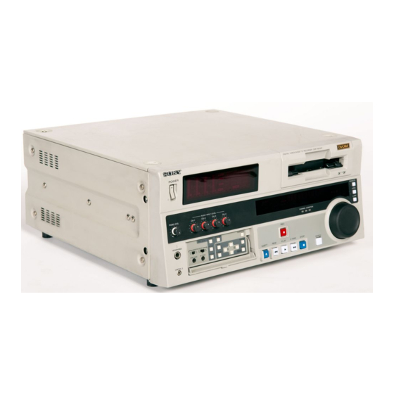
- Page 1 3-204-677-12(1) Digital Videocassette Player Operating Instructions Before operating the unit, please read this manual thoroughly and retain it for future reference. DSR-1600/1600P © 2000 Sony Corporation...
- Page 2 Owner’s Record The model and serial numbers are located at the rear. Record these numbers in the spaces provided below. Refer to them whenever you call upon your Sony dealer regarding this product. Model No. Serial No. WARNING To prevent fire or shock hazard, do not expose the unit to rain or moisture.
-
Page 3: Table Of Contents
Table of Contents Chapter 1 Overview Chapter 2 Playback Chapter 3 Convenient Functions for Editing Operation Chapter 4 Menu Settings Features...5 DVCAM Format ... 5 A Wealth of Interfaces ... 6 Facilities for High-Efficiency Editing... 6 Other Features ... 7 Optional Accessories... - Page 4 Chapter 5 Connections and Settings Chapter 6 Maintenance and Troubleshooting Appendixes Table of Contents Changing the Settings of Basic Items ... 47 Displaying Enhanced Items ... 49 Changing the Settings of Enhanced Items ... 49 Returning Menu Settings to Their Factory Default Settings ...
-
Page 5: Features
The unit is equipped with a variety of functions needed for videocassette players used in professional digital video editing systems. It supports the ClipLink developed by Sony Corporation for highly efficient video editing. When connected to a Sony EditStation serves as part of a powerful non-linear editing system*. -
Page 6: A Wealth Of Interfaces
RS-422A interface or from an optional SIRCS*-compatible remote control unit such as the DSRM-10. * SIRCS (Sony Integrated Remote Control System): A command protocol to remote control Sony professional videocassette recorders/players. Playback control using search dial... -
Page 7: Other Features
DSBK-1602 SDTI (QSDI) Output Board This interface allows the unit to transfer video, audio and time code signals in SDTI (QSDI) format to the Sony EditStation at normal speed. When this unit is connected to another DVCAM VCR, it is possible to transfer compressed signals from this unit to the connected VCR. -
Page 8: Location And Function Of Parts
Location and Function of Parts Front Panel a POWER switch b Audio level meters POWER OVER OVER OVER A Menu control panel (inside of the door) (see page 9) g CONTROL S connector f HEADPHONES connector e PHONE LEVEL control knob a POWER switch Press the “... - Page 9 g CONTROL S connector (stereo minijack) Connect a SIRCS-compatible remote control unit such as the DSRM-10. A Menu control panel The menu control panel is located on the inside of the door at the lower front of the unit. Pull the top of the door to open it.
-
Page 10: Tape Transport Control Section
b MENU button Press this button to display the menu on the monitor screen and the time counter display. Press it again to return from the menu display to the usual display. On how to use the menu, see Chapter 4 “Menu Settings.” c COUNTER SEL (selection) button Selects the type of time data to be shown in the time counter display. -
Page 11: Display Section
e STOP button Press this button to stop the current tape transport operation. C Display section a Playback format indicators b ClipLink indicator c VITC indicator f Cassette memory indicator a Playback format indicators DVCAM: This lights when a tape recorded in DVCAM format is played back. -
Page 12: Search Button
b ClipLink indicator Lights when a cassette is loaded on which ClipLink log data is stored in the cassette memory. For details of ClipLink log data, see the appendix “ClipLink Guide” (page 73). c VITC indicator Lights when VITC is being read regardless of the data shown in the time counter display. -
Page 13: Remote Button
Playback modes using the search dial Playback mode Operation and functions Shuttle Press the SEARCH button or the search dial so that the SHUTTLE indicator in the display section lights, then turn the search dial. Playback is carried out at a speed determined by the position of the search dial. -
Page 14: Rear Panel
Rear Panel A Analog video signal output section (see page 15) DV IN/OUT ANALOG VIDEO REF. VIDEO VIDEO S VIDEO COMPONENT VIDEO (SUPER) AC IN connector Use the supplied power cord to connect this to an AC outlet. Location and Function of Parts B Digital signal output section (see page 16) SDI OUT SDTI(QSDI)OUT... - Page 15 A Analog video signal output section ANALOG VIDEO a REF. VIDEO IN/OUT connectors a REF. (reference) VIDEO IN/OUT connectors (BNC type) Input a reference video signal. The IN connector block has a built-in automatic 75 termination switch. When a signal is input to the upper REF. VIDEO IN connector with no bridging (loop-through) connection made, the connector is terminated with an impedance of 75 automatically.
- Page 16 B Digital signal output section (optional DSBK-1601/1602/1803 boards required) DV IN/OUT connector (6-pin IEEE-1394) (optional DSBK-1803 i.LINK/DV Input/Output Board required) This i.LINK-compatible connector (subsequently referred to also as the i.DV IN/OUT connector) outputs digital video and audio signals in DV format. Note When searching at speeds in the range + times normal speed, the audio signal output...
- Page 17 C Analog audio signal output section AUDIO OUT a AUDIO OUT CH-1 (channel 1) to CH-4 connectors (XLR 3-pin, male) These connectors output channel-1 to channel-4 analog audio signals, respectively. It is possible to use the AUDIO OUT CH-3 and AUDIO OUT CH-4 connectors for audio monitor output for channels 1 and 2, respectively (use the OUTPUT CH3/4 menu item (see page 45).
- Page 18 Location and Function of Parts...
-
Page 19: Playback
Playback Usable Cassettes Playback This section describes the necessary settings and operations to perform playback on this unit. The same settings and operations apply whether you are using the unit as part of an editing system, for dubbing, or as a stand-alone player VCR. For the necessary connections and settings not covered in this section, see Chapter 5 “Connections and Settings.”... - Page 20 DVCAM cassettes Notes on using cassettes Checking the tape for slack Playback The following figure illustrates the DVCAM cassettes. REC/SAVE switch Set to SAVE to prohibit recording on the tape. Mini size Cassette memory This memory is used to store ClipLink log data. For details of ClipLink log data, see the appendix “ClipLink Guide”...
-
Page 21: Inserting And Ejecting Cassettes
Inserting and Ejecting Cassettes Inserting a cassette No double insertion of cassettes Ejecting a cassette This unit accepts three sizes of cassette: L (standard size), M (medium size: DVCPRO) and S (mini size). When inserting a cassette in the unit, make sure its tape window faces upward as shown in the following figure. -
Page 22: Settings For Playback
Settings for Playback Playback Player (DSR-1600/1600P) OVER OVER OVER OVER PB FS 48k44.1k32k Power on this unit by pressing on the Power on the video monitor and set its switches as shown below. Switch Setting termination switch ON (or attach a 75 Input switch Set according to the type of input signal from this unit. -
Page 23: Playback Procedure
Playback Procedure OVER OVER OVER OVER PB FS 48k44.1k32k Note When controlling this unit from an editing control unit connected to the REMOTE connector on this unit, press the REMOTE button to turn it on. When not, turn the button off. Insert a cassette. - Page 24 Playback If the following indicators light when a cassette is loaded Indicator It means: Cassette memory indicator The loaded cassette contains a cassette memory. ClipLink indicator There is ClipLink log data stored in the cassette memory on the loaded cassette. To perform the following operations Operation Do this:...
-
Page 25: Repeat Playback-Automatic Cyclical Playback
Repeat Playback—Automatic Cyclical Playback Setting Points A and B for Repeat Playback Setting the current tape position as point A or B Proceed as follows to perform automatic cyclical playback of recording (repeat playback) between selected start and end points. Set the desired repeat start and end points using the REPEAT FUNCTION menu item (see page 40). - Page 26 Inputting time code values for points A and B Playback Once set, the point A or B time code value is held in the non-volatile memory of the unit until changed. It is not lost when the unit is powered off. Note When setting point A or B, you can only use a time code value.
- Page 27 With “SETUP MENU” selected, press the Bk button. The display changes as follows. SETUP MENU OPERATIONAL FUNCTION DISPLAY CONTROL TIME CODE SETUP BANK OPERATION MENU GRADE :BASIC Monitor screen With “OPERATIONAL FUNCTION” selected, press the Bk button. The display changes as follows. SETUP MENU OPERATIONAL FUNCTION REPEAT FUNCTION...
- Page 28 Playback Press the j button to select “REPEAT TOP.” SETUP MENU OPERATIONAL FUNCTION REPEAT FUNCTION REPEAT MODE :OFF REPEAT TOP :T.TOP REPEAT END :V.END A PRESET B PRESET Monitor screen Press the Bk button. The display changes as follows. SETUP MENU OPERATIONAL FUNCTION REPEAT FUNCTION :T.TOP...
- Page 29 Press the KA button. The display changes as follows. SETUP MENU OPERATIONAL FUNCTION REPEAT FUNCTION :OFF REPEAT MODE REPEAT TOP :V.END REPEAT END A PRESET B PRESET Monitor screen Press the j button to select “A PRESET.” SETUP MENU OPERATIONAL FUNCTION REPEAT FUNCTION :OFF REPEAT MODE...
-
Page 30: Cuing Up To Any Desired Position Set As Point A Or B
Cuing Up to Any Desired Position Set as Point A or B Playback Press the J or j button to increment or decrement the value of the flashing digit. Each press of the button increments or decrements the value. Holding the button down increments or decrements the value continuously. -
Page 31: Displaying Time Data And Other Text Information
Convenient Functions for Editing Operation Displaying Time Data and Other Text Information This unit allows time data and operation mode indications to be displayed on the monitor screen. Time data can also be displayed in the time counter display on the unit. Displaying Time Data and Operation Mode Indications The unit is provided with the following functions related to... -
Page 32: Time Data Type
A Time data type The following time data type indications are displayed. Indication Description Count value of the time counter Time code data from time code reader (factory default setting) User bit data from time code reader TCR. Time code data from VITC reader UBR. -
Page 33: Counter Display
To display the desired time data in the time counter display Time data type indicators Time counter display OVER OVER OVER OVER PB FS 48k44.1k32k COUNTER SEL button Open the door on the lower part of the front panel, and press the COUNTER SEL button. -
Page 34: High-Speed And Low-Speed Search-Quickly And Accurately Determining Editing Points
High-Speed and Low- Speed Search—Quickly and Accurately Determining Editing Points Use the search function to easily locate the desired scene and to quickly and accurately determine edit points. Search Operations via External Equipment You can control the unit in the following operation modes from an editing control unit (ES-7, PVE-500, etc.) connected to the REMOTE connector on the rear panel or from a SIRCS-compatible remote control unit such as the... - Page 35 Turn the search dial in the desired direction at the speed corresponding to the desired playback speed. Playback in jog mode starts. To stop playback in jog mode, stop turning the search dial. Playing back in shuttle mode In shuttle mode, you can control the speed of playback by the angular position of the search dial.
- Page 36 High-Speed and Low-Speed Search—Quickly and Accurately Determining Editing Points...
-
Page 37: Menu Organization
Menu Settings Chapter Menu Organization As shown in the following figure, the menu system consists of four levels and is functionally divided into two subsystems: the setup menu and the digital hours meter display menu. This chapter mainly describes the setup menu, showing its contents and how to operate it. - Page 38 Menu organization Menu selection level SETUP MENU (Continued) Menu Organization Level 1 OPERATIONAL FUNCTION REPEAT FUNCTION LOCAL ENABLE SEARCH ENABLE MAX SRCH SPEED JOG RESPONSE PREROLL TIME AFTER CUE-UP PLAY START AUTO REW CHARA. DISPLAY DISPLAY CONTROL CHARA. POSITION CHARA. TYPE CHARA.
- Page 39 Menu selection level (Continued) AUDIO CONTROL SETUP BANK OPERATION MENU GRADE T1:OPERATION HOURS METER T2:DRUM ROTATION T3:TAPE RUNNING CT:THREADING Level 1 Level 2 LEVEL SELECT OUTPUT CH3/4 JOG CONTROL SHUTTLE MUTE DV PB ATT RECALL BANK1 RECALL BANK2 RECALL BANK3 RECALL BANK4 SAVE BANK 1 SAVE BANK 2...
-
Page 40: Menu Contents
Menu Contents Setup Menu The purpose and settings of the setup menu items are described below. Indications of menu items and settings • In the table below entitled “Menu contents,” the indication of each menu item or setting on the monitor screen is shown first, then the indication of the same item or setting in the time counter display of this unit is shown in square brackets ([ ]). - Page 41 OPERATIONAL FUNCTION [Operational]: Operation settings MAX SRCH SPEED [>Max SHUTTLE [>>SHUTTLE]: SRCH]: Specify the Specify the maximum maximum tape speed in tape speed in search search mode (shuttle) and mode (shuttle). F.FWD (fast forward)/REW F.FWD/REW [>>F.FWD/ (rewind) mode. REW]: Specify the maximum tape speed in F.FWD/REW mode.
- Page 42 DISPLAY CONTROL [Display]: Settings related to indications on the monitor and the unit CHARA. DISPLAY [> Chara disp]: Determine whether or not to output text (such as time code values) from the VIDEO OUT 2 (SUPER) connector. CHARA. POSITION [> Chara pos]: Set the position of text superimposed on output from the VIDEO OUT 2 (SUPER) connector to the monitor.
- Page 43 DISPLAY CONTROL [Display]: Settings related to indications on the monitor and the unit ALARM [> ALARM]: Determine whether alarm messages are issued or not. REF ALARM [> REF ALARM]: Determine whether alarm messages related to reference video signal are issued or not.
- Page 44 TAPE PROTECTION [Tape protct]: Settings related to tape and video head protection FROM STILL [> From STILL]: Set the time to switch from still search mode to tape protection mode. Also select the type of tape protection mode. VIDEO CONTROL [Video]: Settings related to video control Description of settings (For DSR-1600 only) SETUP ADD [>...
- Page 45 VIDEO CONTROL [Video]: Settings related to video control Description of settings PROCESS CONTROL [>Proc CONTROL DEV [>>Ctrl ctrl] dev]: Select the method of controlling the internal digital video processor. C PHASE MODE [>>C Phas MD]: Select the phase rotation mode for chroma phase control.
- Page 46 AUDIO CONTROL [Audio]: Settings related to audio control SHUTTLE MUTE [>Shutl mute]: Set the audio muting conditions during shuttle playback. DV PB ATT [>DV PB ATT]: When playing back a tape recorded in consumer DV format, select whether to attenuate the audio output level. SETUP BANK OPERATION [Setup Bank]: Settings related to menu bank operations RECALL BANK1 [>Recall 1]: Recall menu settings from...
-
Page 47: Changing Menu Settings
Changing Menu Settings This section explains how to change menu settings. Buttons Used to Change Settings Use the following buttons on the menu control panel to change the menu settings. Menu control buttons Functions MENU button • Opens the menu and launches menu control mode. - Page 48 With “SETUP MENU” selected, press the k button. This displays all items on menu level 1. Level-1 menu display SETUP MENU OPERATIONAL FUNCTION DISPLAY CONTROL TIME CODE SETUP BANK OPERATION MENU GRADE :BASIC Monitor screen Press the J or j button to select the required item. Example: Display when “DISPLAY CONTROL”...
-
Page 49: Displaying Enhanced Items
To change other settings, press the K button to return to the previous screen, then repeat steps 5 to 7 as required. When you have completed the settings, press the SET (YES) button. The message “NOW SAVING...” appears on the monitor screen, and “Saving...”... -
Page 50: Returning Menu Settings To Their Factory Default
Follow the same procedure as in steps 3 to 8 of the procedure in the section “Changing the Settings of Basic Items” on page 47 using the arrow buttons to select an item and change its setting. When you have completed the settings, press the SET (YES) button. -
Page 51: Connections For A Digital Non-Linear Editing System
Connections and Settings Chapter Connections for a Digital Non-Linear Editing System This unit can be connected to an ES-7 EditStation to configure a digital non-linear editing system. If you use the SDTI (QSDI) interface with the optional DSBK-1602 board installed in the unit, you can transfer video, audio, time code, and other compressed data from this unit to the ES-7. - Page 52 REF. VIDEO SDTI(QSDI)OUT VIDEO OUT 2 DSR-1600/1600P (SUPER) Composite video input Video monitor Settings on the DSR-1600/1600P Button Setting REMOTE On (lit) Connections for a Digital Non-Linear Editing System REMOTE AUDIO MONITOR OUT Audio input A 75 B 9-pin remote control cable (not supplied) C Cable with RCA phono plugs (not supplied)
-
Page 53: Connections For A Cut Editing System
Connections for a Cut Editing System The following figure shows a cut editing system configuration which includes a DSR-1600/1600P unit as the player and a DSR-1800/1800P as the recorder. DSR-1600/1600P (player) SDTI(QSDI)OUT VIDEO AUDIO OUT 2 MONITOR (SUPER) Composite Audio input video input Source monitor Settings on the DSR-1600/1600P (player) and... -
Page 54: Connections For An A/B Roll Editing System
Connections for an A/B Roll Editing System The following is an example configuration of A/B roll editing system using the DSR-1600/1600P. In this configuration, the recorder is a DSR-1800/1800P unit, player 1 is a DSR-1600/1600P unit, and player 2 is an analog Betacam UVW-1600/1600P Videocassette Player unit. - Page 55 Main video monitor Video signal generator (Sony Tektronix TSG- 130, etc.) DFS-500/500P DME Switcher Video signal Audio signal Reference video signal Control signal Source video monitor DSR-1800/1800P (recorder) PVE-500, etc. (editing control unit) DSR-1600/1600P (player 1) a) When using a DFS-500/500P DME Switcher, the phase of the video signals processed by the DFS-500/500P is delayed.
- Page 56 Audio monitor system connections The following shows an example of audio monitor system connections. For details of these connections, refer to the instruction manual for each connected device. Speaker (left channel) Audio amplifier Cables with RCA phono plugs MONITOR MONITOR OUT 1 OUT 2 MXP-290 Audio Mixer...
- Page 57 Control signal connections The following shows an example of control signal connections to enable the editing control unit to control all other A/B roll editing system devices. 9-pin remote control cable Mixer control mode selection switch: PARALLEL RECORDER MIXER SWITCHER PLAYER 2 9-pin remote control cable 9-pin remote control cable...
-
Page 58: Video/Audio Signal Connections
LINE OUT 2 LINE OUT 1 MIC/LINE MXP-290 Audio Mixer A 12-pin/3-BNC cross cable (not supplied; consult your Sony dealer about this cable.) B 12-pin dubbing cable (not supplied) C Cable with XLR connectors (not supplied) Settings on the DSR-1800/1800P... - Page 59 Connection of a video monitor Set up the following connections to enable monitoring of video and audio signals on a video monitor. In addition to the video and audio signals, you can have time data, the operation mode of the unit, alarm messages, and other information displayed as text on the monitor screen by setting the CHARA.
-
Page 60: Adjusting The Sync And Subcarrier Phases
Subcarrier phase adjustment is necessary when using composite signals and Y/C signals. Switcher (DFS-500/500P) DSR-1800/1800P (recorder) coaxial cable (A) coaxial cable (B) PVE-500 Editing Control Unit Vectorscope (Sony Tektronix 1750/1751, etc.) - Page 61 Performing a phase adjustment operation Press the SCH button on the vectorscope. The vectorscope switches to SCH mode. Press the B channel button on the vectorscope. This displays the black burst signal from the switcher. Press the EXT button on the vectorscope. This switches the vectorscope to external synchronization mode.
- Page 62 Adjusting the Sync and Subcarrier Phases...
-
Page 63: Maintenance
These counts can be displayed on the monitor screen and in the time counter display of this unit. Use them as guidelines for scheduling maintenance. In general, consult your Sony dealer about necessary periodic maintenance checks. Digital hours meter display modes The digital hours meter has the following four display modes. - Page 64 Displaying the digital hours meter Use the following procedure. Press the MENU button on the menu control panel. The menu selection level display appears on the monitor screen and in the time counter display. Menu selection level display SYSTEM MENU SETUP MENU HOURS METER Monitor screen...
-
Page 65: Head Cleaning
To end the digital hours meter display Press the MENU button on the menu control panel. To reset the trip values About this operation, consult your Sony dealer. Head Cleaning Always use the DVM12CL (mini size) or DV12CL (standard size) Cleaning Cassette to clean the video and audio heads. -
Page 66: Troubleshooting
Troubleshooting If an alarm message appears on the monitor screen, or if the unit appears to be malfunctioning, please check the following before contacting your Sony dealer. Tape problem Symptom Cause The unit’s tape The REMOTE button is lit and the... -
Page 67: Error Messages
Error Messages This unit is provided with a self-diagnostic function that detects internal abnormalities. When it detects an abnormality, it outputs an error message to the monitor screen and indicates an error code in the time counter display. AN ERROR HAS BEEN DETECTED. - Page 68 Alarm messages and associated directions Direction The tape will automatically be ejected after cleaning is completed. Correct the setup menu settings. Contact your Sony dealer if this alarm message appears again after making corrections. Use a tape without cassette adaptor.
-
Page 69: Precautions
Precautions On safety • Should any liquid or solid object fall into the cabinet, unplug the unit and have it checked by qualified personnel before operating it further. • Unplug the unit from the wall outlet if it is not to be used for an extended period of time. -
Page 70: Specifications
Specifications General Signal system DSR-1600: NTSC DSR-1600P: PAL Power requirements 100 V to 240 V AC, 50/60 Hz Power consumption (with all options installed) DSR-1600: 70 W/120 V DSR-1600P for Europe: 70 W/220 V Peak inrush current (1)Power ON, current probe method: 40 A (100 V), 40 A (240 V) (2)Hot switching inrush current, measured in accordance with... -
Page 71: Processor Adjustment Range
Video performance Band width Composite (DSR-1600): 30 Hz to 4.2 MHz ±1.0 dB (Y) Composite (DSR-1600P): 25 Hz to 4.8 MHz ±1.0 dB (Y) S-video (DSR-1600): 30 Hz to 5.0 MHz ±1.0 dB (Y), 5.75 MHz +0/ 3.0 dB (Y) (TM) S-video (DSR-1600P): 25 Hz to 5.0 MHz ±1.0 dB (Y), 5.5 MHz +1.0/ 2.0 dB (Y),... -
Page 72: Related Equipment
Analog audio outputs AUDIO OUT XLR 3-pin, male (× 4), +4/0/ 3*/ 6 dBm, 600 balanced AUDIO MONITOR OUT Phono jack, unbalanced * Selectable on DSR-1600P only Digital audio outputs DIGITAL AUDIO (AES/EBU) OUT (with optional DSBK-1601 SDI/AES/EBU Output Board installed) BNC type (×2), complying with AES- 3id-1995 Output for headphones... -
Page 73: Cliplink Guide
ClipLink Guide What Is ClipLink? The ClipLink function greatly improves the efficiency of the video production process as a whole by recording various editing-related data on tape when shooting. As such, ClipLink is a revolutionary function that transcends the conventional separation of shooting and editing. How ClipLink Changes Video Production Techniques The following describes various ways in which ClipLink*... -
Page 74: Example System Configuration And Operation Flow
Example System Configuration and Operation Flow The following illustration shows an example system configuration for using the ClipLink function and a typical ClipLink operation flow. Shooting ClipLink log data transfer DSR-85/1800/1600 DSR-85P/1800P/1600P Digital Videocassette Recorder/Player Editing DSR-85 /1800/1600 or DSR- /1800P/1600P Digital Videocassette Recorder/Player... -
Page 75: Data Generated When Shooting
Data Generated When Shooting The following describes the kinds of data that is generated when using the ClipLink function. Index pictures When shooting, a single-frame image from the Mark IN point at the start of each scene is recorded as a still picture into the camcorder’s internal memory. - Page 76 How to record ClipLink log data The following describes how to record the various ClipLink log data items. OK/NG status To designate a scene as “NG,” press the NG button on the camera while shooting the scene or at any time before you begin shooting the next scene.
- Page 77 Time codes recorded for Mark IN/OUT points There is a gap between actual time codes and Mark IN/ OUT time codes recorded in the cassette memory, as shown in the figure below. The time code value is rounded up at each Mark IN point and rounded down at each Mark OUT point, to a whole number of seconds.
-
Page 78: Glossary
Glossary A/B roll editing An editing method that uses two or more playback VCRs to create special effects such as dissolve and wipe, and uses one record VCR to record the results of the editing. Using an editing control unit allows efficient control of the VCRs and very precise editing. - Page 79 Abbreviation of Signal-to-Noise (ratio). The higher the S/N value, the less noise and higher the picture quality. Search mode A VCR operating mode used when searching for specific scenes, by viewing the video output or time code values while playing back the tape at various speeds in forward or reverse direction.
- Page 80 Glossary...
-
Page 81: Index
Index Numerics 9PIN button 13 A/B roll editing system 54 AC IN connector 14 AES 6, 16 Alarm messages 67 Analog audio signal output section 17 video signal output section 15 Arrow buttons 10 Aspect ratio 7 AUDIO (AES/EBU) OUT connectors Audio level meters 8 AUDIO MONITOR OUT connector Audio monitor system connections 56... - Page 82 Optional accessories 7 PB FS display 8 PCM digital audio 5 PHONE LEVEL control knob 8 PLAY button 10 Playback 19 jog mode 13, 34 procedure 23 shuttle mode 13, 35 Playback format indicators 11 POWER switch 8 Power-on playback function 7 Precautions 69 Processor adjustment range 71 Rack mount 7...
- Page 84 Sony Corporation Printed in Japan...