
Related Manuals for Sony DSR-1500A


Summary of Contents for Sony DSR-1500A
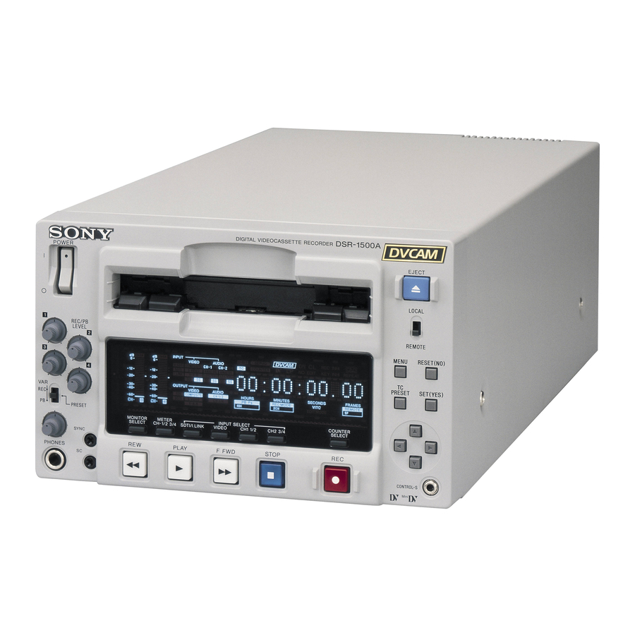
- Page 1 3-619-326-13 (1) Digital Videocassette Recorder Operating Instructions Before operating the unit, please read this manual thoroughly and retain it for future reference. DSR-1500A/1500AP © 2002 Sony Corporation...
-
Page 2: Important Safety Instructions
The model and serial numbers are located at the bottom. Record these numbers in the spaces provided below. Refer To prevent fire or shock hazard, do not to them whenever you call upon your Sony dealer expose the unit to rain or moisture. regarding this product. - Page 3 The manufacturer of this product is Sony Corporation, 1- WARNING: THIS WARNING IS APPLICABLE FOR USA ONLY. 7-1 Konan, Minato-ku, Tokyo, Japan. Using this unit at a voltage other than 120 V may require The Authorized Representative for EMC and product the use of a different line cord or attachment plug, or both.
-
Page 4: Table Of Contents
Table of Contents Chapter 1 Overview Features................. 6 DVCAM Format ............... 6 Variety of Interfaces..............7 Compact Size ................7 Facilities for High-Efficiency Editing........7 Other Features ................8 Optional Accessories..............8 Location and Function of Parts........... 9 Front Panel ................9 Rear Panel ................ - Page 5 Auto Mode (AUTO FUNCTION) Execution Menu....72 Changing Menu Settings ........... 73 Buttons Used to Change Settings..........73 Changing the Settings of Basic Items ........73 Displaying Enhanced Items ............ 75 Changing the Settings of Enhanced Items ......75 Returning Menu Settings to Their Factory Default Settings... 76 Displaying Supplementary Status Information....
-
Page 6: Features
Using the material, editing can be carried out to single-frame precision. DVCAM is a professional -inch digital recording format The unit can also be used for recording in DV format (in developed by Sony from the consumer DV component SP mode only). digital format. Features... -
Page 7: Variety Of Interfaces
DSBK-1501 board, SDTI (QSDI)-format video, audio negative direction to reverse movement. and time code signals can be transferred between the unit and the Sony EditStation at normal speed. When this unit Digital jog sound function is connected to another DVCAM VCR, it is possible to When searching at speeds in the range ±0.5 times normal... -
Page 8: Other Features
For analog video output and SDI-format video output, you can use menu items to adjust the video output level, chroma signal output level, setup level (for DSR-1500A), Superimposition function black level (for DSR-1500AP), and chroma phase. -
Page 9: Location And Function Of Parts
Location and Function of Parts Front Panel f Cassette compartment g LOCAL/REMOTE switch POWER EJECT a POWER switch h EJECT button LOCAL b Audio level meters REC/PB LEVEL REMOTE MENU RESET(NO) INPUT OVER OVER REC INHI U-BIT SERVO VIDEO AUDIO V:SDTI COMPOSITE CH-1 1/2... - Page 10 a POWER switch d SC (subcarrier phase) control Press the “ ” side to power on the unit. This causes the Turn this control to accurately adjust the subcarrier phase audio level meters and the display section to light. To of the composite video output signal of the unit with power off the unit, press the “...
- Page 11 A Audio input/output level control section When CH-1/2 mode is selected with the METER CH-1/ 2 3/4 button: a REC/PB LEVEL control knobs Audio level meters PHONES MONITOR connector connector CH-1 (channel 1) only. Channel 1 only Channel 1 only REC/PB Only the left meter lights.
- Page 12 B Video/audio input setting section c CH1 1/2 (audio channel 1 or 1/2) button Each press of this button cycles through the following input audio signal selection options for audio channel 1 (when in 2-channel mode) or for audio channels 1 and 2 INPUT SELECT SDTI/i.LINK VIDEO...
- Page 13 is possible to adjust the audio levels on the two channels separately. You can switch the audio recording mode with the REC MODE menu item (see page 66). The selection is indicated by the REC MODE display on the front panel. Location and Function of Parts...
-
Page 14: Display Section
C Display section d Time data type indicators e SERVO indicator f Recording/playback tape format indicators g Cassette memory indicator INPUT REC INHI U-BIT SERVO VIDEO AUDIO V:SDTI COMPOSITE CH-1 1/2 CH-2 3/4 COUNTER EDIT REPEAT SDTI S VIDEO ANALOG ANALOG i.LINK Y-R,B... - Page 15 DSBK-1501 board required) Y/CPST Y signal SDI: SDI audio signal (optional R−Y/C/CPST C signal DSBK-1501 board required) (3.58 MHz for DSR-1500A/ SG: Audio test signal (factory default 4.43 MHz for DSR-1500AP) setting) B−Y/CPST (SUPER) Composite signal • When Y R,B is selected: –...
- Page 16 COUNTER: Count value of the time counter U-BIT: User bit data Starts flashing when the remaining capacity of the tape is TC: SMPTE time code (for DSR-1500A) or EBU time for about 2 minutes. code (for DSR-1500AP) l REPEAT (repeat playback) indicator...
-
Page 17: Play Button
o REC MODE (audio recording mode) display under the control of either an editing control unit This indicates the audio recording mode currently selected connected to the REMOTE connector or equipment with the REC MODE menu item (see page 66). connected to the i.DV IN/OUT connector. -
Page 18: Menu Button
E Menu control section e fFgG (arrow) buttons Use these buttons to move around the menu items, and also to modify the initial time code value and user bit data. a MENU button When the SEARCH ENABLE menu item (see page 60) is set to ENABLE, you can also use these buttons to carry out b RESET (NO) button the following playback operations. -
Page 19: Rear Panel
Rear Panel a AC IN connector AC IN AUDIO IN VIDEO Y/CPST R-Y/C A Analog video/audio signal input section (see page 20) REF.VIDEO VIDEO OUT (SUPER) AUDIO OUT Y/CPST R-Y/C/CPST B-Y/CPST MONITOR B Analog video/audio signal output section (see page 21) OUT1 OUT2 SDI/SDTI... - Page 20 MODE menu item (see page 66). The selection is indicated Connectors Input signals by the REC MODE display on the front panel. Y/CPST Y signal R−Y/C C signal (3.58 MHz for DSR-1500A/ 4.43 MHz for DSR-1500AP) B−Y — (not usable) Location and Function of Parts...
- Page 21 AUDIO OUT 1/3 Audio channel 1 (when 1/2 CH is R−Y/C/CPST C signal selected) or audio channel 3 (when 3/ (3.58 MHz for DSR-1500A/ 4 CH is selected) 4.43 MHz for DSR-1500AP) AUDIO OUT 2/4 Audio channel 2 (when 1/2 CH is B−Y/CPST...
- Page 22 C Digital signal input/output section (optional DSBK-1501 Digital Input/Output Board) The connectors in this section are available when the optional DSBK-1501 board is installed. a SDI/SDTI (QSDI) IN connector b SDI/SDTI (QSDI) OUT1/OUT2 connectors c AUDIO (AES/EBU) IN 1/2 and AUDIO (AES/EBU) IN 3/4 connectors d AUDIO (AES/EBU) OUT 1/2 and AUDIO (AES/EBU) OUT 3/4 connectors...
-
Page 23: Usable Cassettes
Recording and Playback Chapter Usable Cassettes This unit can use the DVCAM cassettes listed below. Model name Size PDV-64*/94*/124*/184* Standard size PDVM-12*/22*/32*/40* Mini size The * in each model name is actually “ME” (indicating that a cassette memory is contained), or “N” (indicating that no cassette memory is contained). The numbers in each model name indicate the maximum recording/playback time (in minutes) for each model. - Page 24 DVCAM cassettes The following figure illustrates the DVCAM cassettes. REC/SAVE switch For details of this switch, see “Preventing accidental erasure” on page 25. Mini size Standard size Cassette memory This memory is used to store ClipLink log data. Notes on using cassettes •...
-
Page 25: Inserting And Ejecting Cassettes
Preventing accidental erasure Set the REC/SAVE switch on the cassette to SAVE to prevent accidental erasure of recorded contents. REC/SAVE switch Set to SAVE SAVE To enable re-recording Set the REC/SAVE switch to REC. When this switch is set to SAVE, the unit cannot record on the tape. Inserting and Ejecting Cassettes Inserting a cassette This unit accepts three sizes of cassette: L (standard size), M (medium size:... - Page 26 No double insertion of cassettes When you insert a cassette, the orange lock-out plate appears in the cassette compartment to prevent double insertion. Ejecting a cassette Press the EJECT button. EJECT button INPUT OVER OVER U-BIT SERVO REC INHI VIDEO AUDIO V:SDTI COMPOSITE...
-
Page 27: Recording
Recording This section describes the necessary settings and operations to perform recording on this unit. The same settings and operations apply whether you are using the unit as part of an editing system, for dubbing, or as a stand-alone recorder. For the necessary connections for recording and the settings not covered in this section, see Chapter 5 “Connections and Settings.”... -
Page 28: Settings For Recording
Settings for Recording Player (DSR-1600/1600P, etc.) OVER OVER OVER OVER PB FS 48k44.1k32k Video monitor INPUT signal display section LOCAL/REMOTE switch Recorder (DSR-1500A/1500AP) OVER OVER INPUT REC INHI U-BIT SERVO VIDEO AUDIO V:SDTI COMPOSITE CH-1 1/2 CH-2 3/4 COUNTER EDIT... - Page 29 When the REMOTE indicator is lit, selection of the time data type is carried out at the editing control unit. Select the formats of video and audio input signal to be recorded. Use the INPUT SELECT buttons in the video/audio input setting section to select the desired signal formats.
-
Page 30: Recording Procedure
Select the audio mode. Select either two-channel mode (2 CHANNEL) or four-channel mode (4 CHANNEL) with the REC MODE menu item (see page 66). The corresponding indicator lights in the REC MODE display. Audio mode Lit indicator in the REC MODE display 2-channel mode 4-channel mode Cautions... - Page 31 REMOTE Y-R,B 48K 44.1K 32K 2CH 4CH EDIT MODE 9P i.LINK PLAY F FWD STOP Recorder (DSR-1500A/1500AP) OVER OVER OVER OVER PB FS 48k44.1k32k Player (DSR-1600/1600P, etc.) Notes • When controlling this unit from an editing control unit connected to the REMOTE connector of this unit, set the LOCAL/REMOTE switch to REMOTE, turning the REMOTE indicator on.
- Page 32 If the REC INHI indicator lights: It indicates that the REC/SAVE switch of the loaded cassette has been set to SAVE. Press the EJECT button in the tape transport control section to remove the cassette, then set the REC/SAVE switch to REC and reload the cassette.
- Page 33 Reference level: Reference level the audio level to −12 dB of the DVCAM source with the level control knob. VAR switch : PRESET a) On the DSR-1600A/1600AP, tape recorded at the reference level is played back. b) DSR-1500A/1500AP only Recording...
-
Page 34: Playback
VCR. For the necessary connections for playback and the settings not covered in this section, see Chapter 5 “Connections and Settings” (page 79). Settings for Playback Video monitor Player (DSR-1500A/1500AP) OVER OVER INPUT REC INHI... -
Page 35: Playback Procedure
Playback Procedure LOCAL/ REMOTE switch OVER OVER INPUT REC INHI U-BIT SERVO VIDEO AUDIO V:SDTI COMPOSITE CH-1 1/2 CH-2 3/4 COUNTER EDIT REPEAT SDTI S VIDEO ANALOG ANALOG i.LINK Y-R,B AES/EBU AES/EBU SDI SG SDI SG OUTPUT VIDEO AUDIO COMPOSITE CH 1/2 HOURS MINUTES... - Page 36 To perform the following operations Operation Do this: Stop playback. Press the STOP button. The unit enters stop mode, and will automatically switch to standby off mode after the time set with the STOP TIMER menu item (see page 64) for tape protection.
-
Page 37: Repeat Playback-Automatic Cyclical Playback
Repeat Playback—Automatic Cyclical Playback Proceed as follows to perform automatic cyclical playback of recording (repeat playback) between selected start and end points. Set the desired repeat start and end points with the REPEAT FUNCTION menu item (see page 59). You can set points A and B as start and end points by following the procedure described in the next section. - Page 38 Setting the current tape position as point A or B Proceed as follows to set the current tape position as point A or B for repeat playback. MENU RESET(NO) OVER OVER INPUT REC INHI AUDIO U-BIT SERVO VIDEO PRESET SET(YES) V:SDTI COMPOSITE CH-1 1/2...
- Page 39 Inputting time code values for points A and B Using the following procedure, you can modify the time code value for point A or B. MENU RESET(NO) 1,15 PRESET SET(YES) 8,11 2,3,4,6,10,11 5,7,9,12 Press the MENU button. The following menu display appears. SYSTEM MENU Setup menu SETUP MENU...
- Page 40 With “OPERATIONAL FUNCTION” selected, press the G button. The display changes as follows. SETUP MENU >REP FUNC OPERATIONAL FUNCTION REPEAT FUNCTION Time counter display AUTO EE SELECT LOCAL ENABLE :STP&EJ Monitor screen With “REPEAT FUNCTION” selected, press the G button. The contents of the REPEAT FUNCTION menu item are displayed.
- Page 41 Press the G button. The display changes as follows. SETUP MENU >>> Tape top OPERATIONAL FUNCTION REPEAT FUNCTION Time counter display :T.TOP REPEAT TOP :V.END * TAPE TOP A POINT Monitor screen Press the F button to select “A POINT.” SETUP MENU >>>...
- Page 42 Press the F button to select “A PRESET.” SETUP MENU >> A preset OPERATIONAL FUNCTION REPEAT FUNCTION Time counter display :OFF REPEAT MODE REPEAT TOP :V.END REPEAT END A PRESET B PRESET Monitor screen Press the G button. The A PRESET MODE screen appears. The time code value of the current point A is displayed below the screen title.
-
Page 43: Cuing Up To Any Desired Position Set As Point A Or B
Press the SET (YES) button to confirm the defined value. The message “NOW SAVING...” is displayed on the monitor screen and “Saving...” is shown in the time counter display while the new setting is being saved in memory. Caution The new setting may be lost if you power off the unit during the saving operation. -
Page 44: Setting The Time Data
Convenient Functions for Editing Operation Chapter Use the DISPLAY CONTROL menu items (see page 61) Setting the Time Data to select the information displayed and the character type and position of the indications. When you set the SUB STATUS menu item (see page 62) This unit is provided with the following functions related to other than OFF, you can also display supplementary to time data. - Page 45 Tape loading E DSR-1500A/1500AP operation mode UNTHREADING Tape unloading a) This character (.) can appear on the DSR-1500A only. The STANDBY OFF Standby off mode character to appear in these two columns is always a colon ( : ) on the DSR-1500AP.
-
Page 46: Using The Internal Time Code Generator
To display the desired time data in the time To reset the CNT value Press the RESET (NO) button in the menu control section. counter display This resets the CNT value to 0:00:00:00. Note During playback, if the recording on the tape includes discontinuities, the counter may operate incorrectly at the Time data type indicators corresponding points. -
Page 47: Synchronizing Internal And External Time Codes
“FREE RUN” or “REC RUN” usual status. DF MODE Normally “ON (DF)” (for DSR-1500A only) Note The set data may be lost if you power off the unit while Press the TC PRESET button in the menu control the above saving operation is in progress. Wait until section. -
Page 48: Rerecording The Time Code-Tc Insert Function
automatically synchronize with the external time code Press the MENU button in the menu control section. input to the unit via the SDTI or i.LINK interface. SYSTEM MENU Setup menu Once an external time code signal has been input, the SETUP MENU internal time code advancement mode and frame count AUTO FUNCTION... - Page 49 Press the F button to select “TC INSERT.” Press the SET (YES) button. Time code recording starts from the current tape position. AUTO FUNCTION MENU TC insert SDTI DUBBING i.LINK DUBBING Time counter display TC INSERT TC INSERT Executing Time counter display EXECUTING.
- Page 50 TC INSERT Not DVCAM! Time counter display TC INSERT IS ABORTED DUE TO NON DVCAM FORMAT SOURCE. PUSH THE YES BUTTON. Monitor screen Press the SET (YES) button to end the operation and do it over again after replacing the tape with one recorded in DVCAM format.
-
Page 51: High-Speed And Low-Speed Search-Quickly And Accurately Determining Editing Points
Note High-Speed and Low- When controlling this unit from external equipment, set the REMOTE I/F menu item (see page 68) and the Speed Search—Quickly LOCAL/REMOTE switch so that the remote mode indicators in the display section are on or off as follows. and Accurately •... -
Page 52: Digitally Dubbing Signals In Dvcam/Dv Format
Connections for dubbing via i.LINK interface Digitally Dubbing Signals To carry out dubbing through the i.LINK interface, connect the i.DV IN/OUT connectors on this unit and the in DVCAM/DV Format player. Use the following procedure. In addition to straightforward tape dubbing, you can also use this unit to dub signals in DVCAM/DV format MENU RESET(NO) - Page 53 Press the G button. Insert the source tape in the player, and the recording tape in this unit. This displays the items on level 1 of the auto mode execution menu. A message to confirm the dubbing operation appears. AUTO FUNCTION MENU SDTI DUB SDTI DUBBING Start dub?
- Page 54 6, the cassette memory capacity of the Monitor screen (Example display cassettes inserted in both this unit and the player are for DSR-1500A) checked automatically. If the cassette memory capacity of the source tape is larger than that of the recording tape, the above message appears.
- Page 55 After execution SDTI DUBBING No DVCAM/DV (A/V/TC/CM) Time counter display DUBBING COMPLETED. HOWEVER, A NON DVCAM/ DV(SP) FORMAT SEGMENT WAS ON THE SOURCE TAPE. PUSH THE SET BUTTON. ABORT:MENU KEY Monitor screen In either case, the source tape section recorded in DV (LP) format is dubbed as a no-signal section.
-
Page 56: Menu Organization
Menu Settings Chapter Menu Organization As shown in the following figure, the menu system consists of four levels and is functionally divided into three subsystems: the setup menu, the auto mode (AUTO FUNCTION) execution menu and the digital hours meter display menu. - Page 57 TCG REGEN UB BINARY GP. VITC POS SEL-1 VITC POS SEL-2 VITC OUTPUT EE OUT PHASE MUTE IN SRCH TAPE PROTECTION FROM STOP STOP TIMER FROM STILL STILL TIMER NEXT MODE (Continued) a) Menu item for DSR-1500A only Menu Organization...
- Page 58 SAVE BANK 3 SAVE BANK 4 MENU GRADE AUTO FUNCTION SDTI DUBBING A/V/TC A/V/TC/CM i.LINK DUBBING A/V/TC TC INSERT A/V/TC/CM HOURS METER T1:OPERATION T2:DRUM ROTATION T3:TAPE RUNNING CT:THREADING a) Menu item for DSR-1500A only b) Menu item for DSR-1500AP only Menu Organization...
-
Page 59: Menu Contents
Menu Contents Setup Menu The purpose and settings of the setup menu items are Examples: described below. Indication on monitor Indication in time counter screen display Indications of menu items and settings OPERATIONAL FUNCTION [Operational] • In the table below entitled “Menu contents,” the CASSETTE OUT [>>... - Page 60 OPERATIONAL FUNCTION [Operational]: Operation Description of settings settings AUTO EE SELECT [> Auto EE]: CASSETTE OUT [>> *EE [>>> EE]: Output video and audio signals received from Determine whether the unit Cass. out]: Operations other equipment. enters EE mode or PB mode when the cassette has PB [>>>...
- Page 61 Factory default setting: 5 FRAME DELAY [>> 5 delay] (for before switching to playback mode is the same on all the decks DSR-1500A) or 4 FRAME DELAY [>> 4 delay] (for DSR- of the editing system. It is then no longer necessary to...
- Page 62 DISPLAY CONTROL [Display]: Settings related to Description of settings indications on the monitor and the unit SUB STATUS [> Sub status]: Select supplementary status *OFF [>> OFF]: Nothing of supplementary status information information superimposed on output from the B−Y/CPST EDIT PRESET [>> Edit pre]: Indications of the editing mode (SUPER) connector to the monitor.
- Page 63 Set to FREE RUN when carrying out editing with an editing control unit. With the REC RUN setting, editing will not be carried out correctly. (For DSR-1500A only) *ON (DF) [>> ON (DF)]: Drop frame mode DF MODE [> DF mode]: Select whether the time code OFF (NDF) [>>...
- Page 64 TIME CODE [Time code]: Settings related to the time code Description of settings generator VITC POS SEL-1 [> VITC pos-1]: Select a line to insert the (For DSR-1500A) VITC in. 20 LINE [>> 20 line] to 12 LINE [>> 12 line]: Select any line from 12 to 20.
- Page 65 INPUT VIDEO [>> INPUT]: Use the input video signal selected with the VIDEO button in the video/audio input setting section. (For DSR-1500A only) *OFF [>> OFF]: Do not remove black setup. SETUP REMOVE [> Setup rmv]: Determine whether or not to ON (REMOVE) [>>...
- Page 66 CHROMA PHASE [>> C 00 [>>> 00] to FF [>>> FF] phase]: Adjust the Factory default setting: 80H chroma phase. (For DSR-1500A only) 000 [>>>000] to 3FF [>>> 3FF] SETUP LEVEL [>> Setup Factory default setting: 200H lev]: Adjust the black setup level.
- Page 67 INT AUDIO SG [> Audio SG]: Select the operation of the SILENCE [>> silence]: Silent signal *1kHz SINE [>> 1kHz]: 1-kHz, −20 dB FS (for DSR-1500A) or internal audio test signal generator. −18 dB FS (for DSR-1500AP) sine wave signal...
- Page 68 REF. VIDEO IN connector (marked ). For more information about this, consult your Sony dealer. DIGITAL OUTPUT [> Digit Out]: Select the format of signals *SDI [>> SDI]: SDI format to be output from the SDI/SDTI (QSDI) OUT1/OUT2 SDTI [>>...
- Page 69 SETUP BANK OPERATION [Setup Bank]: Settings related Description of settings to menu bank operations RECALL BANK1 [> Recall 1]: Recall menu settings from (1) Select the bank you want to recall, then press the menu bank 1. button. Message “RECALL OK?” appears. RECALL BANK2 [>...
- Page 70 VIDEO LOOP THRU The optional boards (see page 8) corresponding to the input signal formats to be used are required. TIME CODE IN TIME CODE OUT DSR-1500A/1500AP (1st unit) Output device VIDEO IN (VCR, camera, etc.) AUDIO IN VIDEO IN...
- Page 71 VIDEO OUT AUDIO IN TIME CODE OUT AUDIO OUT TIME CODE IN Output device (VCR, camera, etc.) TIME CODE OUT DSR-1500A/1500AP (1st unit) VIDEO IN VIDEO OUT AUDIO IN AUDIO OUT TIME CODE IN TIME CODE OUT DSR-1500A/1500AP (2nd unit)
-
Page 72: Auto Mode (Auto Function) Execution Menu
Auto Mode (AUTO FUNCTION) Execution Menu The following table shows the purpose and function of the For details of the use of individual items, see “Digitally items in the auto mode execution menu. Dubbing Signals in DVCAM/DV Format” on page 52 and “Rerecording the Time Code—TC Insert Function”... -
Page 73: Changing Menu Settings
Changing the Settings of Basic Changing Menu Settings Items The factory default setting is to display only the basic This section explains how to change menu settings. items. To change the settings of basic items proceed as follows. Buttons Used to Change Settings Use the following buttons in the menu control section to MENU RESET(NO) - Page 74 With “SETUP MENU” selected, press the G button. Press the f or F button to select the item whose setting you wish to change. This displays all items on menu level 1. For menu items on level 3, press the G button to go to level 3, then press the f or F button to select the item Level-1 menu display whose setting you wish to change.
-
Page 75: Displaying Enhanced Items
To change other settings, press the g button to return Displaying Enhanced Items to the previous screen, then repeat steps 5 to 7 as required. The factory default setting is not to display enhanced items. When you have completed the settings, press the SET To display enhanced items, set the MENU GRADE menu (YES) button. -
Page 76: Returning Menu Settings To Their Factory Default Settings
With “SETUP MENU” selected, press the G button. To return all settings to their factory default settings This displays all basic and enhanced items on menu level 1. Press the MENU button in the menu control section. Level-1 menu display The menu selection level display appears on the monitor screen. -
Page 77: Displaying Supplementary Status Information
When the SUB STATUS menu item is set to TC MODE: Displaying On-screen Meaning Supplementary Status indication INT PRST FREE The internal time code generator is Information [IP F] operating in FREE RUN mode. INT PRST REC The internal time code generator is [IP R] operating in REC RUN mode. - Page 78 When the SUB STATUS menu item is set to AUDIO MIXING: On-screen indication Meaning 1 2 3 4 Input audio channels [MIX] selected for mixing 1 2 3 4: Input audio channels 1, 2, 3 and 4 Example display: Input audio channels 3 and 4 are mixed and recorded on audio channel 4 on tape.
-
Page 79: Connections For A Digital Non-Linear Editing System
Note Production of some of the peripherals and related devices described in this chapter has been discontinued. For advice about choosing devices, please contact your Sony dealer or a Sony sales representative. Connections for a Digital Non-Linear Editing System This unit can be connected to a nonlinear editor supporting connection and settings on the nonlinear editing DV/DVCAM with an i.LINK cable (DV cable). - Page 80 Settings on the DSR-1500A/1500AP Switch/menu item Setting LOCAL/REMOTE switch REMOTE (REMOTE indicator lights.) DIGITAL OUTPUT menu item SDTI (see page 68) (SDTI indicator lights.) REMOTE I/F menu item (see 9PIN page 68) (9P indicator lights.) For details of video/audio input and audio mode settings, see “Settings for Recording”...
-
Page 81: Connections For A Cut Editing System
The following figure shows a cut editing system Notes configuration that includes two DSR-1500A/1500AP units • This application requires both of the DSR-1500A/ to serve as the player and recorder. 1500AP units (recorder and player) to be fitted with the optional DSBK-1501 board. - Page 82 Settings on the DSR-1500A/1500APs (recorder and player) Switch/menu item Setting LOCAL/REMOTE switch REMOTE (REMOTE indicator lights.) DIGITAL OUTPUT menu item SDTI (see page 68) (SDTI indicator lights.) REMOTE I/F menu item (see 9PIN page 68) (9P indicator lights.) REC FORMAT menu item...
-
Page 83: Connections For An A/B Roll Editing System
• This application requires the DSR-1500A/1500AP unit used as the recorder to be fitted with the optional DSBK- 1505 board. • The DSR-1500A/1500AP units shown in the following figure are fitted with the optional DSBK-1501 and DSBK-1505 boards. • When using the DSR-1500A/1500AP unit as the... - Page 84 Audio mixer (MXP-290, etc.) Editing control unit (PVE-500, etc.) DME switcher (DFS-500/ 500P, etc.) UVW-1600/1600P, DSR-1500A/1500AP (player 1) etc. (player 2) Video signal Audio signal Reference video signal Control signal a) An I/O delay of several frames occurs on DME switchers and other devices equipped with frame memory.
- Page 85 DSR-1500A/1500AP (recorder) Audio amplifier REF. VIDEO Cables with RCA phono plugs MONITOR MONITOR OUT 1 OUT 2 DSR-1500A/1500AP (player 1) REF. VIDEO Audio mixer (MXP-290, etc.) REF. VIDEO IN 75 Ω termination switch: ON UVW-1600/1600P, etc. (player 2) REF. VIDEO IN Editing control unit (PVE-500, etc.)
- Page 86 The following shows an example of control signal connections to enable the editing control unit to control all other A/B roll editing system devices. DSR-1500A/1500AP (recorder) 9-pin remote control cable REMOTE DSR-1500A/1500AP (player 1) Mixer control mode selection switch: 9-pin remote control cable REMOTE PARALLEL RECORDER UVW-1600/1600P, etc.
- Page 87 C Cable with XLR AUDIO OUTPUT connectors (not supplied) CH-2 CH-1 UVW-1600/1600P, etc. (player 2) Settings on the DSR-1500A/1500AP (recorder) For details of the video/audio input and audio mode settings, see “Settings for Recording” on page 28. Switch/menu item Setting LOCAL/REMOTE switch...
- Page 88 Settings on the DSR-1500A/1500AP (player) Connection of a video monitor Set up the following connections to enable monitoring of Switch/menu item Setting video and audio signals on a video monitor. In addition to LOCAL/REMOTE switch REMOTE the video and audio signals, you can have time data, the...
- Page 89 Settings on an editing control unit When connecting an editing control unit, make the settings as follows, according to the model. PVE-500 No settings are required. BVE-600/900/910/2000 (NTSC model) or FXE-100/ Set the VCR constants as follows. 10 11 12 13 14 15 80 17 00 96 05 05 03 80 0A 08 FE 00 80 5A FF BVE-600/900/910/2000 (PAL model) or FXE-100P/ 120P...
-
Page 90: Connections For Sdti (Qsdi) Dubbing
The following shows an example of connections for Notes digitally dubbing SDTI (QSDI) signals (see page 52) using • This application requires both of the DSR-1500A/ a pair of DSR-1500A/1500AP units. 1500AP units (recorder and player) to be fitted with the optional DSBK-1501 board. -
Page 91: Connections For Analog Recording
DSBK- component video signals and two channels of audio signals 1505 board. are recorded between two DSR-1500A/1500AP units. • The DSR-1500A/1500AP units shown in the following figure are fitted with the optional DSBK-1501 and DSBK-1505 boards. Video monitor... - Page 92 Settings on the DSR-1500A/1500AP (player) Switch/menu item Setting LOCAL/REMOTE switch LOCAL Normally +4 dBm OUTPUT LEVEL menu items (see page 67) VIDEO OUTPUT menu item Y−R, B (see page 68) (Y−R,B indicator lights.) AUDIO OUTPUT menu item 1/2 CH or 3/4 CH...
-
Page 93: Adjusting The Sync And Subcarrier Phases
Subcarrier phase adjustment is necessary when be edited. If they are not synchronized, picture instabilities using composite signals and Y/C signals. or color break-up may occur at edit points. DSR-1500A/1500AP (player 1) Switcher (DFS-500/500P) DSR-1500A/1500AP (recorder) UVW-1600/1600P, etc. (player 2) 75 Ω... - Page 94 Performing a phase adjustment operation Note When component signals are used the subcarrier phase Press the SCH button on the vectorscope. indicator does not appear. The vectorscope switches to SCH mode. Output the player 2 signal, and repeat steps 6 and 7 to adjust the sync and subcarrier phases of the output Press the B channel button on the vectorscope.
-
Page 95: Maintenance
Use them as guidelines for scheduling maintenance. condensation, and if a tape is run in this state, the tape may In general, consult your Sony dealer about necessary stick to the drum and can be easily damaged. To lessen the periodic maintenance checks. - Page 96 Displaying the digital hours meter Digital hours meter indications on the monitor screen Use the following procedure. All four counts (T1, T2, T3, and CT) are indicated on the monitor screen. Press the MENU button in the menu control section. The menu selection level display appears on the Resettable trip counts monitor screen and in the time counter display.
-
Page 97: Head Cleaning
To end the digital hours meter display Press the MENU button in the menu control section. To reset the trip values About this operation, consult your Sony dealer. Head Cleaning Always use the DVM12CL (mini size) or DV12CL (standard size) Cleaning Cassette to clean the video and audio heads. -
Page 98: Troubleshooting
Troubleshooting If an alarm message appears on the monitor screen, or if the unit appears to be malfunctioning, please check the following before contacting your Sony dealer. Tape problems Symptom Cause Remedy Recording is not The cassette’s REC/SAVE switch is set Set the REC/SAVE switch to REC, or use another cassette. - Page 99 Monitor problems Symptom Cause Remedy Set the CHARA. DISPLAY menu item (see page 61) to ON. Data is not The CHARA. DISPLAY menu item is superimposed on the set to OFF. monitor screen. The monitor is not connected to the Connect the monitor to the B−Y/CPST (SUPER) connector.
-
Page 100: Error Messages
Error Messages This unit is provided with a self-diagnostic function that Note detects internal abnormalities. When it detects an To display error messages on the monitor screen, connect abnormality, it outputs an error message to the monitor the monitor to the B−Y/CPST (SUPER) connector, and set screen and indicates an error code in the time counter the CHARA. - Page 101 A non-standard ref. signal is being used Use a standard signal. REF NON-STD for REF. VIDEO. Abnormal settings selected in setup Correct the setup menu settings. Contact your Sony ILL. SETUP! menu. dealer if this alarm message appears again after making corrections.
- Page 102 Alarm messages and associated directions Alarm message on monitor screen Direction Alarm message in time (Cause) counter display Tape end has been detected. Use a new cleaning tape. Tape end! Tape not editable. Use a tape recorded in DVCAM format. Not DVCAM! Use a tape recorded in 525/60 format.
-
Page 103: Precautions
Appendixes Avoid violent impacts Precautions Dropping the unit, or otherwise imparting a violent shock to it, is likely to cause it to malfunction. Do not obstruct ventilation openings On safety To prevent the unit from overheating, do not obstruct • Should any liquid or solid object fall into the cabinet, ventilation openings, by for example wrapping the unit in unplug the unit and have it checked by qualified a cloth while it is in operation. -
Page 104: Specifications
Tape transport control system Specifications Tape speed (DVCAM format) DSR-1500A: 28.193 mm/s DSR-1500AP: 28.221 mm/s General Recording/playback time (DVCAM format) Using PDV-184ME standard-size cassette: Signal system DSR-1500A: NTSC Maximum 184 minutes DSR-1500AP: PAL Using PDVM-40ME mini-size cassette: Power requirements Maximum 40 minutes... - Page 105 BNC type (×2, loop-through with 75 Ω Composite automatic terminator) Y/CPST, R−Y/C/CPST, and B−Y/CPST (SUPER): 1.0 Vp-p, 75 Ω, sync Black burst 0.286 V (DSR-1500A) or 0.3 V (DSR- negative 1500AP), 75 Ω, negative sync Component Y/CPST: 1.0 Vp-p, 75 Ω, negative sync Composite sync VIDEO IN (optional DSBK-1505 Analog Input Board R−Y/C/CPST and B−Y/CPST (SUPER):...
- Page 106 • Always make a test recording, and verify that it was Stereo phone jack, −∞ to −13 dBu (DSR- recorded successfully. 1500A)/−11 dBu (DSR-1500AP), 8 Ω, SONY WILL NOT BE LIABLE FOR DAMAGES OF unbalanced, −20 dBFS (DSR-1500A)/ ANY KIND INCLUDING, BUT NOT LIMITED TO, −18 dBFS (DSR-1500AP)
-
Page 107: Glossary
Condensation of moisture on the tape input to an input connector to pass transport mechanisms of VCRs Setup (for DSR-1500A) through the unit and exit from an including the head drum. If moisture The difference between the reference... - Page 108 Superimpose Abbreviation of Signal-to-Noise To put a set of characters onto a (ratio). The higher the S/N value, the picture so that both can be seen at the less noise and higher the picture same time. quality. S-video Search mode A signal format in which Y A VCR operating mode used when (luminance) and C (chrominance)
-
Page 109: Index
Dubbing 52 Index SDTI (QSDI) 90 B-Y connector 20 DV 16 B-Y/CPST (SUPER) connector 21 input 12 DVCAM 16, 52 Numerics cassettes 24 2CH indicator 17 digital dubbing 52 Cassette 23 32K indicator 16 format 6 compartment 10 44.1K indicator 16 memory indicator 16 48K indicator 16 CH1 1/2 button 12... - Page 110 Processor adjustment range 104 SMPTE time code 16 Still 51 Maintenance 8, 95 STOP button 17 Menu 56 Subcarrier phase 93 AUDIO CONTROL 66 Rear panel 19 Superimposed text 21 AUTO FUNCTION 72 REC button 17 Superimposition 8 changing settings 73 REC FORMAT 60 Supplementary status information 77 contents 59...
- Page 111 OUTPUT PHASE mode 71 Video performance 104 process control 8 test signal 12 Video/audio input setting section 12 VITC field indication 45 indicator 17 Wide track 6 Y/CPST connector 20, 21 Y-R,B indicator 15 Index...
- Page 112 Sony Corporation http://www.sony.net/...