
Related Manuals for Sony DSR-2000P


Summary of Contents for Sony DSR-2000P
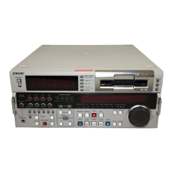
- Page 1 Digital Videocassette Recorder Operating Instructions Before operating the unit, please read this manual thoroughly and retain it for future reference. DSR-2000/2000P 1999 by Sony Corporation 3-867-754-11(1)
- Page 2 Table of Contents Owner’s Record The model and serial numbers are located in the rear. Record these numbers in the spaces provided below. Refer to them whenever you call upon your Sony dealer regarding this product. Model No. Serial No.
-
Page 3: Table Of Contents
Table of Contents Chapter1 Overview Chapter2 Setting/Displaying Time Data and Text Information Chapter3 Recording and Playback Features ... 7 System Configuration ... 11 Location and Function of Parts ... 12 Upper Control Panel ... 13 Lower Control Panel ... 16 Subsidiary Control Panel ... - Page 4 Table of Contents Chapter4 Editing Table of Contents Automatic Editing ... 67 Overview of Automatic Editing ... 67 Button/Switch Settings for Editing ... 70 Selecting an Edit Mode ... 71 Setting Edit Points ... 72 Checking Edit Points ... 75 Modifying Edit Points ...
- Page 5 Chapter5 ClipLink Operation Chapter6 Setup Menu Overview of ClipLink Operation ... 97 Displaying ClipLink Log Data ... 98 Detailed Data Display ... 98 Cuing Up to Mark IN/OUT and Cue Points ... 99 Cuing Up to Any Desired Position ... 99 Cuing Up to Adjacent Mark IN/Cue Points ...
- Page 6 Table of Contents Chapter7 Connections and Settings Chapter8 Maintenance and Troubleshooting Appendixes Table of Contents Reference Video Signals for Analog Signal Editing .. 125 Connections for Cut Editing Using i.LINK Interface (Optional DSBK-190 Required) ... Connections for Digital Nonlinear Editing Using SDTI (QSDI) Interface ...
-
Page 7: Features
The following are the principal features of the unit. DVCAM Format DVCAM is a professional -inch digital recording format developed by Sony from the consumer DV component digital format (4:1:1 for DSR-2000/4:2:0 for DSR-2000P). High image quality and high stability... - Page 8 IN and OUT points. 2) SDI: Serial Digital Interface is used for transferring video signals in component digital format (D1). 3) is a trademark of Sony Corporation and indicates that this product is in agreement with IEEE1394-1995 specifications and their revisions.
- Page 9 This allows searching on the sound track. Video process control For analog video output and SDI-format video output, you can adjust the video output level, chroma signal output level, setup level (for DSR-2000), black level (for DSR-2000P), and chroma phase. Chapter 1 Overview...
-
Page 10: Other Features
DSBK-190 i.LINK/DV Input/Output Board This board enables cut editing between two DSR- 2000/2000P units. It also allows you to connect the unit to other equipment provided with a Sony DV connector to carry out editing or dubbing of digital video and audio signals. -
Page 11: System Configuration
System Configuration The figure below shows example equipment that can be connected to this unit. DVCAM cassette DVCAM camcorder DV cassette DV camcorder DV camcorder DSR-500WS/500WSP ANALOG VIDEO I/O S VIDEO IN/OUT SVO-5800/5800P Microphone a) The DSBK-190 is an optional board. SDI INPUT/OUTPUT SDTI(QSDI) INPUT/OUTPUT... -
Page 12: Location And Function Of Parts
Location and Function of Parts Location and Function of Parts There are four control panels as shown in the figure below. To adjust the position of the lower control panel You can fix the lower control panel in any position between vertical and horizontal for ease of operation. -
Page 13: Upper Control Panel
Upper Control Panel 1 POWER switch 2 Audio level meters 1 Input selection/audio mode display section POWER OVER OVER OVER OVER V:SDTI INPUT VIDEO COMPOSITE CH11/2 ANALOG AUDIO ANALOG CH23/4 PB FS 48k44.1k32k 1 POWER switch Press the “1” side to power the unit on. When the unit is powered on, the display windows in the upper and lower control panels light. - Page 14 Location and Function of Parts 1 INPUT display Indicates the input signal selected with the SDTI/ i.LINK button in the input selection section. V:SDTI: Digital video signal in SDTI(QSDI) format SDTI: Digital video and audio signals in SDTI(QSDI) format i.LINK: Digital video and audio signals in DV format, using i.LINK technology 2 INPUT VIDEO display Indicates the input video signal selected with the...
- Page 15 3 CH1, 1/2 (audio channel 1 or 1/2) button Each press of this button cycles through the following input audio signal selection options for audio channel 1 (when in 2-channel mode) or for audio channels 1 and 2 (when in 4-channel mode). •...
-
Page 16: Lower Control Panel
Location and Function of Parts Lower Control Panel 1 METER FULL/FINE button 2 REC controls CH-1 CH-2 CH-3 CH-4 METER FULL/FINE PHONE LEVEL PULL FOR VARIABLE INSERT VIDEO CH-1 CH-2 CH-3 CH-4 ASSEMBLE DMC EDIT DELETE MEMORY HEADPHONES AUTO EDIT PREVIEW REVIEW 4 Editing control section (see page 21) - Page 17 3 PB (playback) controls These adjust individually the playback levels on channels 1 to 4. During playback, pull out the control knobs and adjust the level while watching the level meters. When the control knobs are pushed in, the playback levels return to the preset levels, and cannot be adjusted.
-
Page 18: Display Section
Location and Function of Parts 4 RESET button To reset a time counter value (COUNTER) shown in the time counter display, press this button. Resetting the COUNTER value erases all edit points. This button is also used for setting time code and user bit values and in setup menu operations. - Page 19 COUNTER: Count value of the time counter U-BIT: User bit data TC: SMPTE time code (DSR-2000) or EBU time code (DSR-2000P) 5 Time counter display Indicates the count value of the time counter, time code, or user bit data depending on the settings of the...
- Page 20 Location and Function of Parts !¡ Tape end alarm indicator Starts flashing when the remaining capacity of the tape is for about 2 minutes. !™ SHUTTLE/JOG indicators When searching in shuttle or variable mode using the search dial, the SHUTTLE indicator lights, and when searching in jog mode using the search dial, the JOG indicator lights.
- Page 21 4 Editing control section 1 DELETE button 2 MOMORY indicator DMC EDIT MEMORY 3 DMC EDIT button AUTO PREVIEW 4 PREVIEW button 5 AUTO EDIT button 1 DELETE button This deletes an existing edit point. Hold down this button and press the IN, OUT, AUDIO IN, or AUDIO OUT button which is lit, indicating an existing edit point.
- Page 22 Location and Function of Parts 8 ENTRY/SHIFT button Use this button for setting edit points, carrying out ClipLink operations, and so forth. • To set a video IN point or OUT point: Hold down the IN button or OUT button, and press this button. •...
- Page 23 4 EDIT button To carry out manual editing, press this button simultaneously with the PLAY button. Monitoring in E-E mode When the unit is in stop mode, pressing this button lights it, and you can monitor the input signal selected with the ASSEMBLE button or INSERT buttons in E- E mode.
- Page 24 Location and Function of Parts Playback modes using the search dial Playback Operations and functions mode Shuttle Press the SHUTTLE button or the search dial so that the SHUTTLE indicator in the display section lights, then turn the search dial. Playback is carried out at a speed determined by the position of the search dial.
-
Page 25: Subsidiary Control Panel
PRESET TC GENERATOR 8 DF/NDF switch (DSR-2000 only) 7 FREE RUN/REC RUN switch 6 INT/EXT PRESET/REGEN switch !™ SET UP (DSR-2000)/BLACK LEVEL (DSR-2000P) knob and PRESET/MANUAL switch !£ CHROMA knob and PRESET/MANUAL switch PRESET 1 CHARACTER switch Select whether or not to superimpose text information... - Page 26 Location and Function of Parts 3 REC (record) INHIBIT switch When this switch is set to ON, the REC INHIBIT indicator in the display section lights, and recording on tape is no longer possible. 4 KEY INHIBIT switch When this switch is set to ON, the KEY INHIBIT indicator in the display section lights, and the buttons in the upper control panel and lower control panel specified by the setting of extended menu item 118 are...
- Page 27 MANUAL: You can adjust the setup level (DSR- 2000) in the range ±30 IRE , or the black level (DSR-2000P) in the range ±210 mV. !£ CHROMA (chrominance) knob and PRESET/ MANUAL switch The switch makes the selection described below.
-
Page 28: Connector Panel
Location and Function of Parts Connector Panel VIDEO CONTROL CONTROL PANEL ~AC IN REMOTE-IN REMOTE-OUT 1 AC IN connector 2 Ground terminal This figure shows the connector panel fitted with the optional DSBK-190 i.LINK/DV Input/Output Board. 1 AC IN connector Use the optional power cord to connect this to an AC outlet. - Page 29 6 S VIDEO OUT connector (4-pin) This connector outputs an S-video signal with separated Y (luminance) and C (chroma: 3.58 MHz for DSR-2000 or 4.43 MHz for DSR-2000P) components. 7 VIDEO IN connectors (BNC type) and 75W termination switch Input an analog composite video signal to one of these connectors.
- Page 30 Location and Function of Parts 8 COMPONENT VIDEO Y/R–Y/B–Y IN connectors (BNC type) Input analog component video signals (Y/R Y/B Y) to these connectors. 9 COMPONENT VIDEO Y/R–Y/B–Y OUT connectors (BNC type) These connectors output analog component video signals (Y/R Y/B Y). 2 Digital input/output section 1 DIGITAL AUDIO (AES/EBU) IN connectors DIGITAL AUDIO I/O(AES/EBU)
- Page 31 5 DIGITAL AUDIO (AES/EBU) OUT connectors (BNC type) These connectors onput digital audio signals in AES/ EBU format. The left-hand connector (CH-1/2) is for audio channels 1 and 2, and the right-hand connector (CH-3/4) is for audio channels 3 and 4. 6 SDI (Serial Digital Interface) INPUT connectors (BNC type) Input digital video and audio signals in SDI (D1)
- Page 32 Location and Function of Parts 2 AUDIO IN LEVEL/600 switches Set these switches for each channel as shown in the following table, according to the audio input levels to the AUDIO IN CH-1 to CH-4 connectors and the impedance. Settings of the AUDIO IN LEVEL/600 switches Audio input Level Impedance...
-
Page 33: Usable Cassettes
Usable Cassettes This unit can use the DVCAM cassettes listed below. Model name PDV-64ME/94ME/124ME/184ME PDVM-12ME/22ME/32ME/40ME The numbers in each model name indicate the maximum recording/playback time (in minutes) for each model. For example, the PDV-184ME has a maximum recording/playback time of 184 minutes. Cassettes usable for playback only All consumer DV cassettes and L- and M-size DVCPRO (25M) cassettes are usable for playback... -
Page 34: Inserting And Ejecting Cassettes
Location and Function of Parts Preventing accidental erasure Set the REC/SAVE switch on the cassette to SAVE to prevent accidental erasure of recorded contents. REC/SAVE switch Set to SAVE SAVE To enable re-recording Set the cassette’s REC/SAVE switch to REC. When this switch is set to SAVE, the unit cannot record on the tape. -
Page 35: Displaying Time Data And Unit's Operating Status-Superimposing Text Information
Displaying Time Data and Unit's Operating Status Superimposing Text Information Setting/Displaying Time Data and Text Information To display superimposed time data and text information about the operating status of the unit on the monitor, set the CHARACTER switch on the subsidiary control panel to ON. When the CHARACTER switch is set to ON, the text information is superimposed on the output of the VIDEO OUT 3 (SUPER) connector and also of the SDI OUTPUT 3 (SUPER) connector. - Page 36 S H U T T L E 5 Recorder/player selection a) This character can appear on the DSR-2000 only. The character to appear in these two columns is always a colon (:) on the DSR-2000P. Note The example above shows the factory default configuration.
- Page 37 2 Time code reader drop-frame mark (for DSR-2000 only) Drop frame mode (factory default setting) Non-drop frame mode 3 Time code generator drop-frame mark (for DSR-2000 only) Drop frame mode (factory default setting) Non-drop frame mode 4 VITC field “ ” (blank): Fields 1 and 3 “*”: Fields 2 and 4 5 Recorder/player selection The indication changes depending on the status of the RECORDER/...
- Page 38 Displaying Time Data and Unit's Operating Status Superimposing Text Information Chapter 2 Setting/Displaying Time Data and Text Information Display Block A Block B CASSETTE OUT TAPE UNTHREAD STANDBY OFF T.RELEASE STOP F.FWD PREROLL PLAY PLAY LOCK PLAY Deviation from normal speed (%) LOCK EDIT...
-
Page 39: Setting Time Code And User Bits
Setting Time Code and User Bits Setting an Initial Time Code Value Set the buttons and switches as shown below. CHARACTER switch DF/NDF switch FREE RUN/REC RUN switch INT/EXT PRESET/REGEN switch Button/switch settings Buttons/switches REMOTE button CHARACTER switch INT/EXT PRESET/REGEN switch FREE RUN/REC RUN switch DF/NDF switch To set an initial time code value, use the following procedure. - Page 40 Setting Time Code and User Bits To set time code to the current time Chapter 2 Setting/Displaying Time Data and Text Information Press the COUNTER SEL button and select TC. Time data type indicator TC lights in the display section of the lower control panel.
- Page 41 To set user bits You can record up to 8 hexadecimal digits of information (date, time, event number, etc.) in the time code track. Proceed as follows. Watching the time data type indicator in the display section, press the COUNTER SEL button and select U-BIT. Carry out steps 2 to 7 of the section “Setting an initial time code value”...
-
Page 42: Synchronizing The Internal Time Code Generator With An External Signal-External Lock
Setting Time Code and User Bits Synchronizing the Internal Time Code Generator With an External Signal—External Lock To synchronize to an external time code signal Chapter 2 Setting/Displaying Time Data and Text Information You can synchronize the internal time code generator to an external time code signal (TC) input to this unit. - Page 43 To check the synchronization to the external signal Set switches on the subsidiary control panel as follows. TC SELECT switch: TC or VITC according as you are synchronizing to TC or VITC NT/EXT–PRESET/REGEN switch: EXT–REGEN (left position) VITC switch: ON (when recording VITC) This starts the internal time code generator running in synchronization with the external time code generator.
-
Page 45: Recording
Recording Preparations for Recording Buttom/switch settings MONITOR SELECT buttons (page 17) : select the audio channels to be monitored. POWER switch: 1 side REC controls (page 16) : adjust the audio recording levels. REC INHIBIT switch (page 26) : OFF INT/EXT–PRESET/REGEN switch (page 26) : select the time code to be recorded. - Page 46 Recording To change the number of audio channels to be recorded Adjusting the audio recording levels To change the display range of the audio level meters Setting the reference level Chapter 3 Recording and Playback Change the setting of extended menu item 818 between 2-channel (2CH) mode and 4-channel (4CH) mode (4CH).
-
Page 47: Recording Time Code And User Bit Values
Recording Time Code and User Bit Values There are the following two ways of recording time code: • Setting an initial value, then recording the output of the internal time code generator • Recording the output of the internal time code generator synchronized to an external time code generator To set an initial value then record the time code Use the procedure described in the section “Setting an Initial Time Code... -
Page 48: Recording Operation
Recording Recording Operation Chapter 3 Recording and Playback To record, use the following procedure. Insert a cassette. For details, see the section “Inserting a cassette” (page 34). Hold down the REC button, and press the PLAY button. Recording starts, the servo locks, and the SERVO indicator in the display section lights. -
Page 49: Playback
Playback Preparations for Playback Buttom/switch settings MONITOR SELECT buttons (page 17) : select the audio channels to be monitored. POWER switch: 1 side PB controls (page 17) : adjust the audio playback levels. Time data selection This section describes playback of video and audio. Before beginning playback, make any necessary button/switch settings. -
Page 50: Playback Operation
Playback Playback Operation Normal playback Chapter 3 Recording and Playback This section describes the following types of playback: • Normal playback Playback at normal ( 1) speed • Playback in jog mode Variable speed playback, with the speed determined by the speed of turning the search dial •... - Page 51 Playback in jog mode If you play back to the end of the tape The tape is automatically rewound, and stops. You can change the setting of extended menu item 125 so that the tape just stops without being automatically rewound when it is recorded to the end. In jog mode, you can control the speed of playback by the speed of turning the search dial.
- Page 52 Playback Playback in shuttle mode Chapter 3 Recording and Playback In shuttle mode, you can control the speed of playback by the angular position of the search dial. The range of playback speed is 32 times normal speed (can be changed using menu item 102). There are detents on the search dial at the still position and at 10 times normal speed.
- Page 53 Playback in variable mode In variable mode, you can finely control (61 steps) the speed of playback in the range of 1 to 2 times normal speed. Noiseless playback is possible in the range of ±1 times normal speed. (The variable mode playback speed range can be changed using extended menu item 119.) There are detents on the search dial at the still position and at 1 times normal speed.
- Page 54 Playback Playback using the capstan override function Chapter 3 Recording and Playback You can use the capstan override function to adjust the playback speed temporarily. This function is convenient for playback phase synchronization with another VCR playing back the same program. (A) Hold down the PLAY button, and turn the search dial in the desired direction to adjust the playback speed.
-
Page 55: Dynamic Motion Control (Dmc) Playback
Dynamic Motion Control (DMC) Playback Overview On-air start point Preroll point Waiting for the on-air cue before starting DMC playback. Stop Press the REVIEW button again at the on-air cue. Starting DMC playback immediately after preroll DMC playback allows you to vary the playback speed for a certain section of a tape, in variable mode (from 1 to +1 times normal speed), and store the varying speed in memory for later playback at the same varying speed. - Page 56 Playback Storing a varying playback speed in memory Chapter 3 Recording and Playback To store the playback speed for DMC playback, use the following procedure. MEMORY indicator Press the DMC EDIT button, turning it on. Either while playing back the recorded tape, or during recording, press the ENTRY button and each of the following buttons simultaneously, to set the start and end points.
- Page 57 Executing DMC Playback Turn the search dial to vary the playback speed. While the MEMORY indicator is flashing, the speed variations are stored in memory. On passing the speed variation end point, the MEMORY indicator changes from flashing to continuously lit, and the variable speed storing ends.
- Page 58 Playback Chapter 3 Recording and Playback You can start DMC playback using either the REVIEW button or PREVIEW button depending on which of the above two methods you use. REVIEW button PREVIEW button To start playback at the on-air cue from the on-air start point Use the following procedure.
-
Page 59: Synchronous Playback
Synchronous Playback Connecting two DSR-2000/2000P units and synchronizing their tape transport, you can carry out two-unit synchronous playback with an accuracy of 0 frame. For equipment/signal connections and basic settings, see the section “Connections for Two-Unit Synchronous Playback” (page 132). Use the following procedure. - Page 60 Playback Chapter 3 Recording and Playback Hold down the ENTRY/SHIFT button, and press the PREVIEW button. Both the recorder and player start preroll followed by synchronous playback by the two units. When setup menu item 004 is set to ON and 305 set to ACCUR on the recorder side, the recorder and player tape transports are synchronized during the preroll allowing two-unit synchronous playback with ±0 frame accuracy to start at the player and recorder IN points.
-
Page 61: Digitally Dubbing Signals In Dvcam Format
Digitally Dubbing Signals in DVCAM Format (Optional DSBK-190 Required When Using i.LINK Interface) In addition to straightforward tape dubbing, you can also use this unit to digitally dub signals in DVCAM format automatically from the beginning of the tape to the end, through an i.LINK or SDTI(QSDI) interface. When a tape recorded on a DSR-1/1P Digital Videocassette Recorder or DSR-300/300P Digital Camcorder is dubbed, the ClipLink log data held in the cassette memory is also copied. - Page 62 Digitally Dubbing Signals in DVCAM Format When Using i.LINK Interface) Chapter 3 Recording and Playback (Optional DSBK-190 Required SYSTEM MENU SDTI DUBBING i.LINK DUBBING Using the search dial in jog mode, select either SDTI DUBBING or i.LINK DUBBING, then press the SET button. The screen changes as follows, allowing you to select a desired group of items for dubbing.
- Page 63 Using the search dial, select a desired group of items for dubbing, then press the SET button. The menu screen changes as follows. (Example: The screen displayed when A/V/TC/CM is selected.) SDTI DUBBING (A/V/TC/CM) INSERT RECORD TAPE IN THIS VTR AND SOURCE TAPE IN THE PLAYER VTR.
- Page 64 Digitally Dubbing Signals in DVCAM Format When Using i.LINK Interface) Chapter 3 Recording and Playback (Optional DSBK-190 Required Press the SET button. The recording tape and source tape are both automatically wound back to the beginning, and dubbing starts. At the same time, the screen changes as follows.
- Page 65 If the cassette memory of the recording tape is not large enough When you insert the recording tape and source tape in this unit and the player, respectively, whereas A/V/TC/CM has been selected as the items for dubbing, their cassette memory contents are checked automatically. If, as a result, the cassette memory capacity of the recording tape is found inadequate, the following message appears.
-
Page 67: Chapter4 Editing
Automatic Editing Overview of Automatic Editing Editing This section describes how to carry out automatic editing with this unit and another VCR connected to the REMOTE-IN or REMOTE-OUT connector. With this unit, you can use the following two edit modes. •... - Page 68 Automatic Editing Chapter 4 Editing Insert edit mode In insert editing, you insert video, audio, and time code at desired positions on an already recorded tape. You can insert all three types of data at the same time or insert one of the types separately. Note Before you use an unrecorded tape in insert editing, a video signal, e.g.
- Page 69 Sequence of editing operations The following flowchart outlines the sequence of operations in automatic editing with two DSR-2000/2000P units. Sequence of Operation Making necessary settings Insert cassettes. • Insert a cassette for recording the results of editing in the recorder. •...
-
Page 70: Button/Switch Settings For Editing
Automatic Editing Notes on video output to the monitor Button/Switch Settings for Editing Recorder settings MONITOR SELECT buttons (page 17) : select the audio channels to be monitored. POWER switch: I side REC controls (page 16) : adjust the audio recording levels. -
Page 71: Selecting An Edit Mode
Player settings POWER switch: I side PB controls (page 17) : adjust the audio playback levels. Selecting an Edit mode PB button (page 18) : lit TC SELECT switch (page 26) : TC or VITC, when displaying time code (In the subsequent description, except where the player is explicitly mentioned, operations are all on the recorder.) Select either assemble mode or insert mode. -
Page 72: Setting Edit Points
Automatic Editing Setting Edit Points To set edit points Chapter 4 Editing Of the four edit points (recorder IN and OUT points, and player IN and OUT points) required, set any three. The last edit point is set automatically. In insert mode, you can set the edit points for video and audio separately (split editing). - Page 73 Setting split edit points Notes In the following cases, the DELETE button begins to flash and you cannot carry out automatic editing. • The OUT point is before the IN point. • All four of the recorder IN and OUT points and the player IN and OUT points have been set.
- Page 74 Automatic Editing Chapter 4 Editing Repeat steps 2 through 4 to set the required edit points. As each edit point is set, the corresponding button changes from flashing to continuously lit. Note During split editing, if you set six or more edit points for the recorder and player, the DELETE button starts to flash, to indicate that editing cannot be executed.
-
Page 75: Checking Edit Points
Checking Edit Points To display the time value for an edit point When the audio IN point is not set for insert editing of audio only As long as the audio OUT point is set, the VCR is ready for preview or editing. -
Page 76: Modifying Edit Points
Automatic Editing To display the duration between two edit points Modifying Edit Points Chapter 4 Editing Press the RECORDER button or PLAYER button to select the VCR on which you wish to check the duration. The button you have pressed lights. Hold down any two of the four edit points (recorder or player IN, OUT, audio IN, and audio OUT points). - Page 77 To modify an edit point To delete an edit point Use the following procedure. Press the RECORDER button or PLAYER button to select the VCR on which you wish to modify the edit point. The button you have pressed lights. Hold down the IN, OUT, AUDIO IN, or AUDIO OUT button corresponding to the edit point you wish to modify, and press the TRIM buttons ( or –).
-
Page 78: Cuing Up To Edit Points
Automatic Editing Cuing Up to Edit Points To cue up to an edit point Chapter 4 Editing Press the RECORDER button or PLAYER button to select the VCR on which you wish to delete the edit point. The button you have pressed lights. Hold down the DELETE button and press the IN, OUT, AUDIO IN, or AUDIO OUT button according to the edit point you wish to delete. - Page 79 To preroll Use the following procedure. Press the RECORDER button or PLAYER button to select the VCR on which you wish to carry out a preroll. The button you have pressed lights. Press the PREROLL button. The tape is wound back to a position 5 seconds (factory default setting) before the edit IN point, and stops.
-
Page 80: Checking Edit Results-Preview
Automatic Editing Checking Edit Results—Preview Chapter 4 Editing When you have set the edit points, the PREVIEW button flashes, indicating that you can carry out a preview. PREVIEW button To carry out a preview, press the PREVIEW button. The PREVIEW button changes from flashing to continuously lit, and the preview is carried out. -
Page 81: Executing Automatic Editing
Monitor output during a preview Executing Automatic Editing Overview of editing operations Preroll point Recorder Preroll Player Time flow During a preview, you can monitor the following video and audio on a monitor connected to the recorder. • From the preroll point to the IN point, you can monitor the playback from the recorder. - Page 82 Automatic Editing Monitor output during an edit Using a single monitor for video and audio on both player and recorder Starting automatic editing Chapter 4 Editing During execution of an automatic edit, on a monitor connected to the recorder, you can monitor the same video and audio as during a preview (see page 81).
- Page 83 To change the OUT point after starting automatic editing operation After starting the automatic editing operation, to end the operation before the preset OUT point, hold down the ENTRY/SHIFT button and press the OUT button. The position where you pressed the button becomes the OUT point, and editing ends.
-
Page 84: Dmc Editing
DMC Editing Overview of DMC Editing Preroll Recorder Playback Preroll time initial speed Player Tape moves at initial speed Chapter 4 Editing You can carry out variable speed editing, controlling the player playback speed from the recorder. The following figure illustrates how the tapes move on both the player and recorder during DMC editing. -
Page 85: Carrying Out Dmc Editing
Carrying Out DMC Editing Setting the edit points and player speed Use the following procedure. MEMORY indicator Press the RECORDER button. Press the ASSEMBLE button or INSERT button to select an edit mode. Press the DMC EDIT button. The unit switches to the DMC edit mode, and the DMC EDIT button lights. -
Page 86: Dmc Editing
DMC Editing To quit the DMC edit mode To execute the DMC edit To check the editing results Chapter 4 Editing Press the PREVIEW button. The tape is prerolled and then the recorder starts operating at normal speed and the player at the set initial speed. On passing the IN point, the MEMORY indicator begins to flash: turn the search dial to vary the playback speed. -
Page 87: Preread Editing
Preread Editing Player Video source Video switcher Digital or analog video input ANALOG VIDEO IN COMPONENT VIDEO IN S VIDEO IN SDI INPUT DSR-2000/2000P(recorder) Digital or analog video output (preread signals) ANALOG VIDEO OUT COMPONENT VIDEO OUT S VIDEO OUT SDI OUTPUT Video and audio signals already recorded on the recorder tape can be used as an edit source for insert editing. - Page 88 Preread Editing Chapter 4 Editing Note • You cannot carry out preread editing using SDTI or i.LINK signals. • When the preread mode is selected (the PREREAD button is lit), to prevent feedback in the loop connection, no E-E video out is available, regardless of the operating mode of the unit.
-
Page 89: Special Editing Methods
Special Editing Methods This section describes the following editing methods. • Quick editing After selecting an edit mode, you can save on editing time by setting the edit points and executing the edit at the same time. • Continuous editing When you execute multiple edits in succession, you can edit from the second time on by setting the player IN and OUT points only. -
Page 90: Quick Editing
Special Editing Methods Quick Editing Chapter 4 Editing After selecting an edit mode, you can save on editing time by setting the edit points and executing the edit at the same time. Press the PLAYER button, turning it on. Stop the tape on the player at the position you wish to make the IN point. -
Page 91: Continuous Editing
To edit even more quickly Continuous Editing Press the AUTO EDIT button. The edit starts. When the edit finishes, the recorder stops at the OUT point and the player stops about 2 seconds after the OUT point. By skipping the preview in the foregoing procedure, you can execute the edit even more quickly. - Page 92 Special Editing Methods Chapter 4 Editing To carry out continuous editing, use the following procedure. Press the PLAYER button, turning it on. Set the player IN and OUT points. For details of how to set IN and OUT points, see the section “Setting Edit Points”...
-
Page 93: Standalone Editing
Standalone Editing This method allows you to use as the player an external device which cannot be controlled remotely through the REMOTE-IN or REMOTE- OUT connector. For example, you can record a color bar signal from a signal generator in the joints between the scenes of an already completed tape. -
Page 94: Manual Editing
Special Editing Methods Manual Editing Chapter 4 Editing To carry out manual editing, start playback on the player beforehand, then use the following procedure. Press the RECORDER button, turning it on. Use the search dial in jog or shuttle mode to find the edit start point (the recorder IN point), and stop the tape just before this point. -
Page 95: Adding A Narration (Sound-On-Sound)
Adding a Narration (Sound-on-Sound) By means of preread editing with an audio mixer connected (see page 87), you can mix in an audio signal with the existing recorded soundtrack, but extension menu item 819 provides a simple sound-on-sound editing function for adding a narration, using this unit alone. To add a narration from microphone input As an example, the following procedure describes how to record a narration mixed with audio channels 1 and 2 already recorded on the tape,... -
Page 97: Chapter5 Cliplink Operation
Overview of ClipLink Operation The ClipLink function provides the following. • Displaying ClipLink log data • Cueing up to Mark IN/OUT points and cue points • Rewriting ClipLink log data (reel numbers, Mark IN/ OUT points, and OK/NG status only) •... -
Page 98: Displaying Cliplink Log Data
Displaying ClipLink Log Data To display ClipLink log data, hold down the ENTRY/ SHIFT button and press the LIST/– button. LIST/– button ENTRY/SHIFT button The following ClipLink log data list appears in the monitor. CLIPLINK LOG DATA LIST (003/196) REEL NO XXXXXXXX 1 M 00:01:23:00 OK 2 M 00:02:35:00 OK... -
Page 99: Cuing Up To Mark In/Out And Cue Points
Cuing Up to Mark IN/OUT and Cue Points Cuing Up to Any Desired Position To cue up to the point specified by the data item selected on the ClipLink log data list, proceed as follows. Using the SEARCH dial, move the selection mark (asterisk) to the desired data item on the ClipLink log data list. -
Page 100: Rewriting Cliplink Log Data
Rewriting ClipLink Log Data You can rewrite the reel number, Mark IN/OUT points and OK/NG status included in the ClipLink log data. Changing the Reel Number To change the reel number of the data item selected on the ClipLink log data list, proceed as follows. Using the search dial, move the selection mark (asterisk) to the desired data item on the ClipLink log data list. -
Page 101: Changing The Ok/Ng Status
Using the search dial, move the selection mark (asterisk) to the desired data item on the ClipLink log data list. The Mark IN point address is stored as the IN point and the Mark OUT point address is stored as the OUT point. - Page 102 Rewriting ClipLink Log Data Hold down the STOP button and press the SET button. This returns to the original ClipLink log data list. Note If you carry out step 5 skipping step 4, the original ClipLink log data list appears again on the monitor and, in this case, the OK/NG status is not rewritten.
-
Page 103: Adding To/Deleting From Cliplink Log Data
Adding to/Deleting From ClipLink Log Data You can add new Mark IN/OUT point data to the ClipLink log data or delete Mark IN/OUT point data from the ClipLink log data. Adding Mark IN/OUT Points Set the setup menu item 129 (CLIPLINK) to ON beforehand, then proceed as follows. - Page 104 Adding to/Deleting From ClipLink Log Data Holding down the DELETE button, press the MARK/+ button. The specified data disappears from the ClipLink log data list. Holding down the ENTRY/SHIFT button, press the MARK/+ button. Note If you exit from the ClipLink log data list skipping step 3, the previous data is restored.
-
Page 105: Automatically Creating New Cliplink Log Data
Automatically Creating New ClipLink Log Data When the setup menu item 129 (CLIPLINK) is set to ON, you can automatically create new Mark IN/OUT points during recording or editing operation. For information about how to operate the setup menu, see Chapter 6 “Setup Menu”... -
Page 107: Chapter6 Setup Menu
Menu System Configuration The setup menu system of this unit comprises the basic menu and extended menu. • Basic menu This menu is used to make settings relating, for example, to the following. – the digital hours meter – the preroll time –... - Page 108 VIDEO OUT 3 (SUPER) connector and SDI OUTPUT 3 (SUPER) connector for superimposed display on the monitor. 00... 0A ...2A (DSR-2000) /00... 09 ...29 (DSR-2000P): The hexadecimal value 00 is for CHARACTER Adjust the vertical screen position (as a hexadecimal value) of the text information...
- Page 109 Item number Item name Item name CHARACTER V- Determine the vertical size of characters such as time code output from the VIDEO OUT SIZE 3 (SUPER) connector and SDI OUTPUT 3 (SUPER) connector for superimposed display on the monitor. 1 : Standard size 2: 2 times standard size MENU DISPLAY Determine the type of characters in menu text output from the VIDEO OUT 3 (SUPER)
-
Page 110: Basic Menu Operations
Basic Menu Basic Menu Operations This section describes the basic menu display and how to change the settings. For information about how to use items B01 to B14, see the section “Menu bank operations (menu items B01 to B14)” (page 112). Displaying the menu MENU button Display section... - Page 111 Changing the currently displayed menu item Search dial SHUTTLE/JOG indicator Turn the search dial. Turning the search dial in the forward direction increments the item number, and turning it in the reverse direction decrements the item number. When you turn the search dial, the item number changes at a rate depending on the search dial position (when the SHUTTLE indicator is lit) or on the search dial rotation rate (when the JOG indicator is lit).
- Page 112 Basic Menu Menu bank operations (menu items B01 to B14) This unit allows four different complete sets of menu settings to be saved in what are termed "menu banks" numbered 1 to 4. Saved sets of menu settings can be recalled for use as required.
-
Page 113: Extended Menu
Extended Menu Items in the Extended Menu The extended menu contains the following items. In the Settings column of the table, the factory default settings are indicated by an enclosing box. Menu items in the 100s, relating to the control panels Item number Item name Settings... - Page 114 Extended Menu Menu items in the 100s, relating to the control panels (continued) Item number Item name Settings JOG DIAL Select the tape speed characteristics for the search dial rotation rate in jog mode. RESPONSE TYPE1 : Tape speed varies linearly over the range –1 to +1. TYPE2: Tape speed varies stepwise as shown in the figure below TYPE3: Tape speed varies linearly over the range –3 to +3, as shown in the figure CONTROL PANEL...
- Page 115 Menu items in the 100s, relating to the control panels (continued) Item number Item name Settings CLIPLINK Select whether to create ClipLink log data. OFF : Do not create. ON: Create. When recording, the recording starting point is made a Mark IN point and the recording ending point is made a Mark OUT point.
- Page 116 Extended Menu Menu items in the 300s, relating to editing operations (continued) Item number Item name Settings AUTO-DELETION Select what happens when an erroneous edit point is set. MANU : A warning is given by flashing the DELETE button on the control panel. INCONSISTENT The operator must manually delete the unnecessary edit point .
- Page 117 Menu items in the 300s, relating to editing operations (continued) Item number Item name Settings EDIT RETRY When editing with two DSR-2000/2000P units, select the operation if the recorder was not synchronized in time. (Make this setting on the recorder.) OFF: Editing is not carried out, and the unit stops.
- Page 118 You can insert the VITC signal in two places. To insert it in two places, set both items 601 and 602. For DSR-2000P Select a line to insert the VITC in. 9H ... 19H ... 22H: Select any line from 9 to 22.
- Page 119 Menu items in the 600s, relating to the time code generator Item number Item name Settings TCG REGEN Select the signal to be regenerated when the time code generator is in the regeneration MODE mode (i.e., when the PRESET/REGEN switch on the subsidiary control panel is set to REGEN, or the unit is in automatic edit mode).
- Page 120 VIDEO IN button, the internal test signal generator operates to output SIGNAL the selected test signal. This signal can also be recorded. GENERATOR CB100 (for DSR-2000P): 100% color bar signal CB75 (for DSR-2000): 75% color bar signal BB: Black burst signal VIDEO SETUP Select whether to remove the setup (7.5%) from the input analog video signals and...
- Page 121 AUDIO Select the audio reference level (headroom) for recording on tape. REFERENCE –12dB LEVEL –16dB –18dB (factory default for DSR-2000P) –20dB (factory default for DSR-2000) Menu items in the 800s, relating to audio control (Continued) Chapter 6 Setup Menu...
- Page 122 Extended Menu Menu items in the 800s, relating to audio controll (continued) Item number Item name Settings AUDIO OUTPUT Select the analog audio output reference level. LEVEL +4dB : Set the analog output level of the signal at the reference level to +40 dBm. 0dB: Set the analog output level of the signal at the reference level to 0 dBm.
-
Page 123: Extended Menu Operations
Extended Menu Operations To use the extended menu, set basic menu item 099 MENU GRADE to ENHAN beforehand. In the extended menu, you can carry out the same operations as in the basic menu except setting of sub- items. To set sub-items Operate as follows. - Page 124 Extended Menu Monitor screen Recording channel numbers ITEM-819 AUDIO INPUT SOURCE ARRANGE Input channel numbers in1 in2 in3 in4 tape -------------------- ch1: ch2: ch3: ch4: Cursor (shows the item selected for menu operations) Holding down the STOP button, turn the search dial to move the cursor to select a combination of input and recording channels.
-
Page 125: Reference Video Signals For Analog Signal Editing
Reference Video Signals for Analog Signal Editing In order to provide stable video and audio signals for analog editing, it is necessary to input a reference video signal synchronized with the video signal to the REF. VIDEO IN connector and set the REF. VIDEO IN 75 termination switch to ON. - Page 126 Connections for Cut Editing Using i.LINK Interface Required) i.LINK(DSBK-190) DSR-2000/2000P (recorder) DSR-2000/2000P (recorder and player) settings Control Setting (recorder) REMOTE button Unlit i.LINK button SDTI/i.LINK button i.LINK (input selection section) Chapter 7 Connections and Settings (Optional DSBK-190 i.LINK(DSBK-190) DSR-2000/2000P (player) 1 6-pin to 6-pin i.LINK cable (supplied with the DSBK-190) Setting (player) i.LINK...
-
Page 127: Connections For Digital Nonlinear Editing Using Sdti (Qsdi) Interface
Connections for Digital Nonlinear Editing Using SDTI (QSDI) Interface This unit can be connected to an ES-7 EditStation to configure a digital non-linear editing system. Using the SDTI (QSDI) interface, you can transfer video, audio, timecode, and other compressed data between this unit and the EditStation. -
Page 128: Connections For Cut Editing Using Sdi Interface
Connections for Cut Editing Using SDI Interface For a cut editing system using this unit together with a DNW-A75/A75P Betacam SX VCR using an SDI connection, the following figure shows an example of the connections. In this example, the DNW-A75/A75P is used as the recorder and this unit is used as the player. -
Page 129: Connections For Preread Editing
Connections for Preread Editing For a preread editing system using two DSR-2000/ 2000P units together with a video switcher, audio switcher and editing control unit, the following figure shows an example of connections. DSR-2000/2000P (recorder) REMOTE IN REF.VIDEO VIDEO IN VIDEO OUT 1 75 coaxial cable... -
Page 130: Settings Required When Connecting An External Editing Control Unit
1 2 3 4 5 6 7 8 9 10 11 12 13 14 15 Setting 80 14 00 96 05 05 03 80 0A 08 FE 00 80 5A FF • When using the DSR-2000P (PAL) Byte No. Block 1... -
Page 131: Connections For Component Analog Recording
Connections for Component Analog Recording The following shows connections for a system in which analog playback signals from another recorder or player are recorded on the DSR-2000/2000P. In this system, the video signals are analog component signals and the audio signals are recorded from audio channels 1 and 2. -
Page 132: Connections For Two-Unit Synchronous Playback
Connections for Two-Unit Synchronous Playback The following shows connections for synchronous playback using two DSR-2000/2000P units. In the following, the controlling unit is referred to as the recorder and the controlled unit as the player. REF.VIDEO IN DSR-2000/2000P (recorder) REMOTE-OUT DSR-2000/2000P (recorder) settings Control Setting... -
Page 133: Connections For Digitally Dubbing Signals In Dvcam
Connections for Digitally Dubbing Signals in DVCAM Format Using i.LINK Interface) You can use this unit to digitally dub signals in DVCAM format automatically from the beginning of the tape to the end, through an i.LINK or SDTI(QSDI) interface. For information about how to carry out digital dubbing, see the section “Digitally Dubbing Signals in DVCAM Format”... -
Page 135: Condensation
Condensation If you move the unit suddenly from a cold to warm location, or if you use it in a very humid place, moisture from the air may condense on the head drum. This is called condensation, and if a tape is run in this state, the tape may stick to the drum and can be easily damaged. -
Page 136: Periodic Maintenance
Use the information as a guide in scheduling periodic maintenance. For periodic maintenance, cousult your Sony dearler. Display modes of the digital hours meter H01: OPERATION mode Displays the total number of hours the unit has been powered on in units of 1 hour. -
Page 137: Troubleshooting
In these states, alarm messages appear in the diaplay section and on the monitor screen. unit appears to be malfunctioning, please check the following before contacting your Sony dealer. Remedy Set the KEY INHIBIT switch on the subsidiary control panel to OFF. - Page 138 Troubleshooting Input problems Symptom Cause It is not possible to record an No SDTI signal is input to the unit. SDTI signal. a) In this state, an alarm message appears in the diaplay section and on the monitor screen. Monitor problems Symptom Cause Data is not superimposed on...
-
Page 139: Error Messages
Error Messages This unit is provided with a self-diagnostic function that detects internal abnormalities. When it detects an abnormality, it outputs an error message to the monitor connected to the unit and indicates an error code in the display section of the unit. AN ERROR HAS BEEN DETECTED. - Page 140 Use a standard signal. Use a standard signal. Correct the setup menu settings. Contact your Sony dealer if this alarm message appears again after making corrections. — Use a tape recorded in 2-channel (48 kHz) or 4-channel (32 kHz) mode.
- Page 141 Alarm messages and associated directions (Continued) Alarm message on monitor screen Cause Remote mode is selected. Tape cannot be replayed. Tape end has been detected. Tape not editable. Tape not recordable. Tape not usable. TC EXTERNAL is selected. TCG REGEN mode is selected. TCG RUN mode is set to REC RUN.
-
Page 143: Notes On Use
Notes on Use Operation and storage locations Avoid operation or storage in any of the following places. • Location subject to extremes of temperature (operating temperature range 5°C to 40°C (41°F to 104°F)) • Location subject to direct sunlight for long periods, or close to heating appliances (Note that the interior of a car left in summer with the windows closed can exceed 50°C (122°F).) -
Page 144: Specifications
Video performance Band width inches) Y/C delay K-factor Unit: mm (inches) 28.193 mm/s (DSR-2000) 28.221 mm/s (DSR-2000P) Using PDV-184ME standard-size cassette: 184 minutes or less Using PDVM-40ME mini-size cassette: 40 minutes or less Using PDV-184ME standard-size cassette: 3 minutes or less... - Page 145 1.0 Vp-p, 75 , sync negative REF. VIDEO IN BNC type 2 (loop-through), black burst, 0.286 Vp-p (DSR-2000) or 0.3 Vp-p (DSR-2000P), 75 , sync negative S VIDEO IN DIN 4-pin 1 Y: 1.0 Vp-p, 75 , sync negative C: 0.286 Vp-p (DSR-2000) or...
-
Page 146: Specifications
S VIDEO OUT DIN 4-pin 1 Y: 1.0 Vp-p, 75 , sync negative C: 0.286 Vp-p (DSR-2000) or 0.3 Vp-p (DSR-2000P), 75 (burst level) COMPONENT VIDEO OUT Y/R–Y/B–Y BNC type 3, component video Y: 1.0 Vp-p, 75 , sync negative R–Y: 0.7 Vp-p, 75... -
Page 147: Cliplink Tm Guide
ClipLink Guide What Is ClipLink? The ClipLink function greatly improves the efficiency of the video production process as a whole by recording various editing-related data on tape when shooting. As such, ClipLink is a revolutionary function that transcends the conventional separation of shooting and editing. -
Page 148: Example System Configuration And Operation Flow
DSR-2000/85/80/60 DSR-2000P/85P/80P/ Digital Videocassette Recorder Editing DSR-2000/85 /80/60 (or DSR-2000P/85P 80P/60P Digital Videocassette Recorder a) The DSR-60/60P is a videocassette player. b) Between the DSR-85/85P and ES-7, quadruple transfer is possible through the QSDI. Appendixes DVCAM standard cassette or DVCAM mini cassette... -
Page 149: Data Generated When Shooting
Data Generated When Shooting The following describes the kinds of data that is generated when using the ClipLink function. Index Pictures When shooting, a single-frame image from the Mark IN point at the start of each scene is recorded as a still picture into the DSR-1/1P’s internal memory. - Page 150 ClipLink Guide How to record ClipLink log data The following describes how to record the various ClipLink log data items. OK/NG status To designate a scene as “NG”, press the NG button on the camera while shooting the scene or at any time before you begin shooting the next scene.
- Page 151 Time codes recorded for Mark IN/OUT points There is a gap between actual time codes and Mark IN/ OUT time codes recorded in the cassette memory, as shown in the figure below. The frame digit is incremented at each Mark IN point and is decremented at each Mark OUT point.
-
Page 152: Glossary
Glossary Glossary AES/EBU format A unified format for digital audio signals. It allows a single XLR connector to carry the signals for two channels. Assemble editing Editing in which new video/audio is added in sequence to the end of existing recorded video/audio. - Page 153 Reference video signal A video signal which contains a sync signal or sync and burst signals, used as a reference for synchronization of video equipment. R–Y signal One of the color difference signals, the R (red) signal minus Y (luminance) signal. Sampling frequency The unit of time used when converting an analog signal with a continuously varying...
- Page 154 Glossary Unthreading See “Unloading”. User bits These are also referred to as “user’s bits”. The user bits are a 32-bit segment of the timecode recording area. The user can select what to record in this segment and how to use the recorded data. For example, it can be used to record date information in addition to the timecode data or ID numbers for tape reels or...
-
Page 155: Index
Index AC IN connector 28 Adding a narration 95 Alarm messages 139 Analog audio input/output section 31 interfaces 8 video input/output section 29 ASSEMBLE button 20 Assemble edit mode 67 Audio level meters 13 recording level 46 AUDIO CH1, CH1/2 (CH2, CH3/4) display 14 AUDIO IN button 21... - Page 156 Index F FWD button 23 Fault display function 23 Features 7 FREE RUN/REC RUN switch 26 Ground terminal 28 Head cleaning 135 HEADPHONES jack 17 HOLD button 18 i.LINK button 15 connector 30 cut editing 125 digital dubbing 61 IN button 22 Initial time code value 39 INPUT display 14 Input selection section 14...
- Page 157 SC knob 27 cut editing 128 INPUT connectors 31 OUTPUT 1, 2, and 3 (SUPER) connectors 31 SDTI (QSDI) digital nonlinear editing 127 INPUT connector 30 OUTPUT connector 30 SDTI/i.LINK button 14 Search control section 23 dial 23 SEARCH button 23 SERVO indicator 19 SET button 17 SET UP knob 27...
- Page 160 Sony Corporation Printed in Japan...