Table of Contents
Advertisement
Advertisement
Table of Contents

Related Manuals for Ferlux FLORA 7


Summary of Contents for Ferlux FLORA 7
- Page 1 Life Quality MANUAL FOR THE USER AND INSTALLATION AIR RANGE...
- Page 3 We thank you for choosing us The Ferlux wood pellet fireplace is a heating system that has been manufactured with the most advanced technology and a high level of quality, which allows you to enjoy the extraordinary feeling of a fire in total safety.
-
Page 4: Table Of Contents
indice TAKING CARE OF THE MANUAL AND HOW TO CONSULT IT..................6 GENERAL WARNINGS AND SAFETY...........................7 2.1. LEGAL WARRANTY..............................8 2.2. TECHNICAL ASSISTANCE...........................8 2.3. SPARE PARTS..............................8 TECHNICAL INFORMATION...............................9 FUEL................................15 4.1. WHAT ARE WOOD PELLETS?..........................15 4.2. PROPERTIES OF WOOD PELLETS........................15 4.3. STORAGE OF WOOD PELLETS........................16 INSTRUCTIONS FOR INSTALLATION...........................16 5.1. - Page 5 6.2.5. [rCLr] TECHNICAL MENU 1......................31 6.2.6. [tPAr] TECHNICAL MENU 2......................31 USE AND FUNCTIONALITY OF THE HEATER......................32 7.1. ADVICE AND CAUTIONS..........................32 7.2. FIRST LIGHTING..............................32 7.3. STATES OF FUNCTIONALITY..........................33 7.3.1. LIGHTING..........................33 7.3.2. NORMAL HEATER OPERATION....................33 7.3.3. HEATER OFF..........................34 7.3.4. MODULATION (“MOD”).........................34 7.3.5. STANDBY............................34 7.3.6.
-
Page 6: Taking Care Of The Manual And How To Consult It
1. TAKING CARE OF THE MANUAL AND HOW TO CONSULT Keep this manual safe and store it in an accessible location close to the unit. In the event that this manual is lost or becomes difficult to read, ask the installer for a copy or enquire directly with the manufacturer, specifying the identifying details of the product. -
Page 7: General Warnings And Safety
FERLUX shall not bear any responsibility in the event that these precautions are shown to have not been met. All national and local regulations, as well as European regulations, must be satisfied when the unit is being installed. All national and local regulations, as well as European regulations, must be satisfied when the unit is operational. -
Page 8: Legal Warranty
• Exceptional circumstances. 2.2 TECHNICAL ASSISTANCE FERLUX is capable or providing a solution to any technical problem regarding the use and maintenance of the unit at any point during its operational life. 2.3 SPARE PARTS Only use original spare parts. -
Page 9: Technical Information
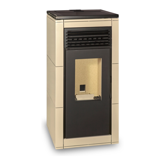
A label that is missing or obscured makes the tasks of installing and repairing the unit more difficult because it may not be possible to identify the product. In the event of it becoming damaged, request a copy from the Technical Support Service. PROPERTIES FLORA 7 FLORA 8 NEREA 8... - Page 10 PROPERTIES LUNA 8 LUNA 10 NEREA 12 NEREA 15 ESTELA 12 ESTELA 15 GÉNESIS 6 GÉNESIS 8 Weight Height 1121 1121 1101 1101 1101 1101 1086 1086 Width Depth Diameter of smoke outlet Diameter of primary air inlet Heatable volume Maximum useful thermal power 15,3 15,3...
- Page 11 MODEL FLORA 7/8 kW MODEL NEREA 8/10 kW...
- Page 12 MODEL NATALIA 10 kW MODEL AROA 8/10 kW...
- Page 13 MODEL LUNA 8/10 kW MODEL NEREA 12/15 kW...
- Page 14 MODEL ESTELA 12/15 kW MODEL GÉNESIS 6/8 kW...
-
Page 15: Fuel
4. FUEL The FERLUX wood pellet heater has been designed to burn wood pellets that comply with the requirements established in Regulation UNE-EN ISO 17225:2014 regarding Solid biofuels and in Regulation ONORM M 7135. 4.1 WHAT ARE WOOD PELLETS? Wood pellets are a combustible fuel that are made by pressing natural dry sawdust. The sawdust is easily compacted and the lignin of the material itself acts as a binder, meaning that no glue or other substance is required. -
Page 16: Storage Of Wood Pellets
The instructions of the manufacturer must be followed, both for the installation as well as the use of the heater and any safety rules and regulations that apply to it must also be met. Failing this, FERLUX is not responsible in the event of any accident occurring. -
Page 17: Protecting The Floor
5.2.1 PROTECTING THE FLOOR If your flooring is flammable (parquet, floating platform) or sensitive to heat, it is necessary to place a protective layer that separates the heater from the floor. This protection must be make of a material that is resistant to fire, such as marble, steel plating, slabs, etc. -
Page 18: Measurements To Pierce Building Envelopes
Smoke ducting or a chimney should be used to vent the gases produced by the heater during combustion to the exterior. The responsibility for the work done to make the smoke ducting lies with the installer, for which reason FERLUX recommends that the installation be carried out by qualified personnel (who are in possession of an installer’s licence) to whom enquiries... -
Page 19: Calculating The Exhaust Smoke Ducting
5.3.2 CALCULATING THE EXHAUST SMOKE DUCTING The following instructions must be taken into account for the path of the chimney: • Tubes made of AISI Type 316 stainless steel, varnished aluminised steel pipes with a minimum thickness of 1.5 mm, and porcelain pipes with a minimum thickness of 0.5 mm shall be used. •... -
Page 20: Installation In Traditional-Type Chimney
The ‘equivalent load loss’ of an installation is the result of the sum of the total metres of the installation added to any additional losses that are shown in the following table: LENGTH TO SUBTRACT FROM THE TOTAL TYPE OF PATH OR ACCESSORY ALLOWED 90°bend Horizontal stretch 45°... -
Page 21: Capping Smoke Outlets
5.3.5 CAPPING OF SMOKE OUTLETS The smoke outlet must always terminate on a vertical and the upper part of the section, which shall be termed the cap, must comply with the following requirements: • It must have a useful internal cross-section equivalent to the evacuation pipes. •... -
Page 22: Electrical Connection
5.5 ELECTRICAL CONNECTION It is necessary to have a mains power outlet of 230 V with a ground connection for the installation of the heater. The power outlet must be capable of conveying at least 450 W of power for the lighting of the heater and must have its own breaker. The heater is powered by means of a power cable that must be connected to the 230 V outlet. - Page 23 The upper display only shows one thing, whereas the lower screen displays varying information depending on the situation. We have classified the displays at each time so that they can be seen below. Depending on the menu item that is open, the display could show the following: •...
-
Page 24: Menú Level 1
6.1 MENU LEVEL 1 The options that the user can access from the ‘Main Screen’ (the screen normally displayed when no buttons have been pressed) are known as ‘MENU LEVEL 1’. 6.1.1 INFORMATION Each time you click the button, you can see the on the lower display an abbreviation for the name of a parameter, and on the upper screen, you can see its value. -
Page 25: Reset Errors, Turning The Heater On And Off
6.1.4 RESETTING ERRORS, TURNING THE HEATER ON AND OFF If you long press the (P1) button, the heater´s state will change from the one it was in before the button was pressed. The following circumstances could arise: STATE BEFORE LONG PRESS STATE AFTER LONG PRESS STOP (no alarm) (The display shows the time and the ON (The display shows Chec, ON1, ON2,...) -
Page 26: Menú Level 2
6.2 MENÚ LEVEL 2 The functions that can be accesed in a submenu that is reached by long pressing (P3) and (P4) are known as `MENU LEVEL 2´. The functions of this submenu are as follows: rAir: Regulation of the fan. Cron: Timer to programme the heater to turn on and off. - Page 27 (ModE) : This allows the “Cron” function to be deactivated or for a choice between three options: Mode Gior: Daily Scheduling SEtt: Weekly scheduling FiSE: Weekend scheduling OFF: The heater does not have any schedule activated When entering (ModE), press the (P3) button and on the upper display (D1), the option that is currently active will be shown (which could be: Gior, SEtt, FiSE or OFF).
- Page 28 In order to configure each schedule, you have to set the ON time and the OFF time. ON MENU SCHEDULING Once you have entered the (ProG) menu, use the (P2) or (P4) buttons to choose one of the three mo- des that you wish to schedule and confirm the selection by pressing the (P3) button.
- Page 29 To adjust the on time, click on the (P3) button and the hours will begin to flash, with the (P3) button, change from hours to minutes and viceversa. To adjust the hour and/or minute values, use the (P2) or (P4) buttons. Once you have set the schedule, push the (P3) button again to save the desired value.
-
Page 30: Orol] Clock
6.2.3 [oroL] CLOCK This function allows you to set the date and the time. This setting is required in order to design schedules for turning the heater on and off. Once you see the following menu displayed on the screen, proceed as follows: Press the (P3) button and the screen will immediately show the following: Press the... -
Page 31: Rclr] Technical Menu 1
After this, the following screen will appear, press the (P3) button and use the (P2) or (P4) to select the ON option to activate the remote control. To confirm, press the (P3) button again. The control unit recognises the remote-control signal (remote control) by means of a code that can be changed. -
Page 32: Use And Functionality Of The Heater
7. USE AND FUNCTIONALITY OF THE HEATER 7.1 ADVICE AND CAUTIONS • Before turning the device on, make sure that there is no flammable material inside or near the heater that could enter the combustion process. • Use fuel that is recommended by the manufacturer. •... -
Page 33: States Of Functionality
At this time, the electronic control board will perform a “ChEc” test on the heater, during which it will carry out a range of verifications. If the control board detects any anomaly, it will not start up and will instead give the corresponding error message. -
Page 34: Heater Off
7.3.3 HEATER OFF The heater can be found in this state when the general switch is turned on or after extinguishing. The time will be displayed on the upper display with the room temperature on the lower display. 7.3.4 MODULATION (“MOD”) This phase occurs during normal operation when the desired room temperature set by the user has been reached. -
Page 35: Recovery Of The Ignition ("Rec")
7.3.7 RECOVERY OF THE IGNITION (`REC´) This stage cuses the heater to turn itself off whilst the word `rEc´ will appear in flashing letters on the upper display. When the turning-off process concludes, the heater will automatically turn itself on. The heater can enter this stage due to the following reasons: •... -
Page 36: Cleaning The Brazier And Brazier Holder
GENERALLY, IT IS NECESSARY TO CLEAN THE BRAZIER AFTER 10-12 HOURS OF CONTINUOUS OPERATION, ALTHOUGH A HIGHER FREQUENCY COULD BE REQUIRED IF INFERIOR PELLETS ARE USED BEFORE TURNING ON THE HEATER, MAKE SURE THAT THE BRAZIER IS PROPERLY SEATED IN POSITION TO CARRY OUT THE CLEANING AND MAINTENANCE TASKS, IT IS NECESSARY THAT THE HEATER BE DISCONNECTED FROM THE MAINS POWER SUPPLY, FULLY TURNED OFF, AND COLD... -
Page 37: Cleaning The Ash Drawer
With an ash vacuum cleaner, remove the ashes that have accumulated in the chamber and inside the brazier holder. 8.2 CLEANING THE ASH DRAWER The ash collection drawer surrounds the brazier holder, which must be regularly emptied to prevent it overflowing with ashes. -
Page 38: Cleaning The Interior Of The Combustion Chamber
7.4 CLEANING THE INTERIOR OF THE COMBUSTION CHAMBER 7.5 CLEANING THE GLASS Regularly clean the glass door of the heater with a degreasing product (not one that is corrosive or abrasive). If the glass is still warm, leave the door open before cleaning for as long as the heater requires to cool down. Do not use materials that could damage or scratch the glass. -
Page 39: Problems, Messages, Errors And Solutions
IF THE GLASS OF THE DOOR IS ACCIDENTALLY BROKEN DURING CLEANING, DO NOT LIGHT THE HEATER AND CONTACT THE TECHNICAL SUPPORT SERVICE SO THAT THEY CAN REPLACE IT (Only an original spare part can be used since the glass has special properties) 9. -
Page 40: Messages
When the heater functions improperly, an alarm or message will normally appear, although this will not always occur. Below, we show some cases that could arise and some checks that it would be useful to do before calling the Technical Support Service: •... -
Page 41: Errors And Solutions
9.3 ERRORS AND SOLUTIONS CODE DESCRIPTION POSSIBLE CAUSE SOLUTION ALARM • Safety thermostat or cable Intervention of the safety broken Notify the Technical Support Er01 thermostat • Excessive temperature in the Service hopper • The chimney is very dirty or Check and clean out the chimney blocked •... - Page 42 ALARM DESCRIPTION POSSIBLE CAUSE SOLUTION CODE Check the desired room temperature and that the • The room is too warm temperature sensor is correctly located to detect the temperature in the room • The room fan is not working Turning-off due to the excessive Er05 or does so very slowly temperature of the smoke...
- Page 43 CODE DESCRIPTION POSSIBLE CAUSE SOLUTION ALARM IF THE BRAZIER IS PRACTICALLY EMPTY Reset the error • There are few wood pellets in Make sure that the wood pellets the hopper can reach the screw and/or pour • A ‘cave’ has formed in the in more if necessary hopped and no wood pellets If no wood pellets fall into the bur-...
- Page 44 CODE DESCRIPTION POSSIBLE CAUSE SOLUTION ALARM • There could be an issue with the smoke outlet • The air inlet could be partially or fully blocked, or has become channelled and a lot of load is Review all the possibilities being lost mentioned for Er02 •...
- Page 45 CERTIFICADO DE GARANTÍA COMMERCIAL WARRANTY Nº ______________________ La presente Garantía Comercial se otorga sin perjuicio además de cualesquiera de los derechos reconocidos por la Ley 23/2003 y RDL 1/2007 frente al vendedor. Para ejercitar sus derechos de conformidad con esta Garantía Comercial, el comprador deberá rellenar este certificado en el punto de venta en el momento de la compra y presentarlo junto con la factura, ticket de compra o albarán de entrega.
- Page 47 FERLUX no se hace responsable en ningún caso de eventuales daños producidos a In no case shall FERLUX be liable for any damge caused to persons or things by improper personas o cosas por manipulación indebida del aparato o por mal uso.
- Page 48 Chimeneas y Barbacoas FERLUX, S.A. Parque Empresarial El Polear, Parc. 1 29313 Villanueva del Trabuco MÁLAGA (España) Tel. + 34 952 03 11 17 / Fax +34 952 03 11 18 www.ferlux.es / e-mail: ferlux@ferlux.es...