Table of Contents
Advertisement
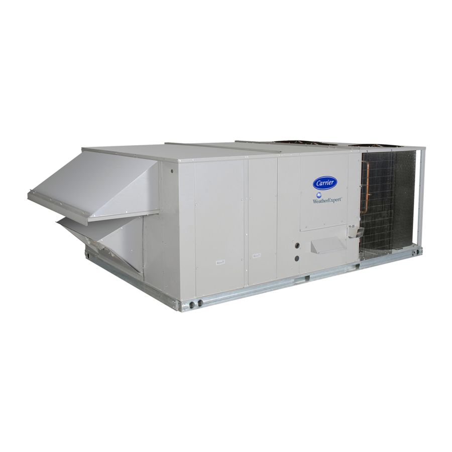
48HJ008-014
Copyright 1999 Carrier Corporation
Product
Data
Single-Package Rooftop Units
High-Efficiency Electric Cooling/
48HJ004-007
48HJD/HJE/HJF
Gas Heating
1
3 to 12
/
Nominal Tons
2
Carrier has designed the Weather-
master series based on customer
needs and requests to be the most
efficient and reliable rooftop unit ever
made.
Features/Benefits
• Most efficient rooftop line for
cooling using scroll compressor
technology
• Most efficient rooftop line for
heating using dimpled heat
exchangers on all units
• High reliability — non-corrosive
condensate pans, prepainted
cabinets and primed interior
panels, and all units are fully
protected by internal safeties
• Quietest operation — all
compressors mounted on
independent vibration isolators.
Standard, belt-driven evaporator
fan motors on all units
• Ease of maintenance achieved by
self diagnostics on the Integrated
Gas Controller (IGC), optional
direct digital controls, standard
size filters, tool-less filter access,
simple compressor access,
permanently lubricated fan
motors, optional disconnect
switch, optional 115-v
convenience outlet, and optional
hinged access panels
• Exclusive MoistureMiser
dehumidification package — a
result of recent advances by
Carrier in controlling comfort
levels. This factory-installed
option significantly improves the
dehumidification capability of the
rooftop unit and helps control
humidity levels in the building.
Form 48HJ-11PD
Advertisement
Table of Contents

Related Manuals for Carrier Weathermaster 48HJD Series


Summary of Contents for Carrier Weathermaster 48HJD Series
- Page 1 Single-Package Rooftop Units Data High-Efficiency Electric Cooling/ Gas Heating 3 to 12 Nominal Tons Carrier has designed the Weather- master series based on customer needs and requests to be the most efficient and reliable rooftop unit ever made. Features/Benefits • Most efficient rooftop line for...
-
Page 2: Table Of Contents
• exclusive Carrier Cycle-LOC™ Carrier means Top Quality Each unit contains a factory print- circuit board that provides anti- and Reliability out indicating tested pressures, compressor cycling amperages, dates, and inspectors, pro- Each component utilized in the • refrigerant filter drier viding certification of the unit’s status... -
Page 3: Features/Benefits
Features/Benefits (cont) SINGLE PIECE SLEEVE BEARING PERMANENTLY TOOL-LESS TOP PANEL FILTER ACCESS LUBRICATED MOTORS ON-SITE CONVERTIBILITY FROM VERTICAL TO HORIZONTAL DISCHARGE HIGH-EFFICIENCY COILS AND ACUTROL™ REFRIGERANT METERING DEVICE SLOPED, NON-CORROSIVE CONDENSATE HIGH-EFFICIENCY COILS MOISTUREMISER DRAIN PAN DEHUMIDIFICATION FULLY MODULATING DURABLADE PACKAGE (FACTORY- INSTALLED OPTION) ECONOMIZER (OPTION OR ACCESSORY) - Page 4 Designed exclusively by is met when Low NO in improving indoor air quality. A Carrier, the controls can be used to CRLOWNOX001A00 is installed on sloped condensate pan eliminates pos- actively monitor all modes of oper- 004-006 sizes.
- Page 5 The circuit acti- • 115-v convenience outlet to power Carrier’s 62AQ Energy$Recycler vates only when needed (using the hu- up electric drills, lights, and refrig- unit solves this dilemma by providing midistat) as opposed to some dehumid- erant recovery machines.
-
Page 6: Model Number Nomenclature
Features/Benefits (cont) • Non-fused disconnect switch to Standardized components for the Resettable 24-v circuit breaker on remove power locally at the roof- complete Weathermaster® line of 48HJ008-014 units allows room top. This option also includes a products are found in all safety devices, for error without replacing transform- power lockout capability to protect condenser-fan motors, evaporator-fan... -
Page 7: Ari Capacities
ARI* capacities UNIT NOMINAL STANDARD COOLING TOTAL SOUND RATING SEER† IPLV 48HJ TONS (Btuh) (Bels) E/F004 1200 36,000 3.21 13.0 11.20 D/E/F005 1450 47,000 4.25 13.0 11.05 D/E/F006 1750 61,000 5.55 13.0 11.00 D/E/F007 2100 74,000 6.70 — 11.00 D/E/F008 3000 90,000 8.18... -
Page 8: Physical Data
Physical data BASE UNIT 48HJ E/F004 D/E/F005 D/E/F006 D/E/F007 NOMINAL CAPACITY OPERATING WEIGHT (lb) Unit Durablade Economizer EconoMi$er MoistureMiser Dehumidification Package Roof Curb COMPRESSOR Scroll Quantity Oil (oz) REFRIGERANT TYPE R-22 Operating Charge (lb-oz) Standard Unit 5- 8 10- 0 9-10 Unit With MoistureMiser Dehumidification Package... - Page 9 BASE UNIT 48HJ E/F004 D/E/F005 D/E/F006 D/E/F007 EVAPORATOR COIL Enhanced Copper Tubes, Aluminum Double Wavy Fins, Acutrol™ Feed Device Rows...Fins/in. 2...15 2...15 4...15 4...15 Total Face Area (sq ft) FURNACE SECTION Rollout Switch Cutout Temp (F)† Burner Orifice Diameter (in..drill size)** Natural Gas —...
- Page 10 Physical data (cont) BASE UNIT 48HJ D/E/F008 D/E/F009 D/E/F012 D/E014 NOMINAL CAPACITY (tons) OPERATING WEIGHT (lb) Unit 1035 1050 Durablade Economizer EconoMi$er MoistureMiser Dehumidification Package Roof Curb COMPRESSOR Scroll Quantity Oil (oz) (each compr) REFRIGERANT TYPE R-22 Operating Charge (lb-oz) Standard Unit Circuit 1 7-10...
- Page 11 BASE UNIT 48HJ D/E/F008 D/E/F009 D/E/F012 D/E014 FURNACE SECTION Rollout Switch Cutout (Temp (F)* Burner Orifice Diameter (in..drill size)† Natural Gas — Std .120...31 .120...31 .120...31/.120...31/.129...30 .120...31/.129...30 Liquid Propane — Alt** .096...41 .096...41 .096...41/.096...41/.102...38 .096...41/.102...38 Thermostat Heat Anticipator Setting (amps) Stage 1 .14/.14/.14 .14/.14/.14...
-
Page 12: Options And Accessories
Options and accessories LOW AMBIENT CONTROLS ITEM OPTION* ACCESSORY† The 48HJ004-014 standard units are designed to operate in Energy$Recycler cooling at outdoor temperatures down to 25 F. With acces- Apollo Direct Digital Controls sory Motormaster ® I control (condenser-fan speed modula- tion), or Motormaster IV control (condenser-fan cycling), units Integrated Economizer (Durablade) can operate at outdoor temperatures down to –20 F. - Page 13 PLUG DAMPER thermostat is rapidly changed. Time Guard II device mounts ACTUATOR in the control compartment of unit. The Time Guard II device is not required when a Carrier programmable thermostat is applied. OUTDOOR AIR TEMPERATURE SENSOR BAROMETRIC...
- Page 14 HUMIDISTAT MOISTUREMISER % RELATIVE HUMIDITY Apollo direct digital controls are designed exclusively by Carrier, and are used to actively monitor all modes of operation as well as Field-installed, wall-mounted humidistat is used to control evaporator-fan status, filter status, indoor-air quality, supply-air tem- operation of the MoistureMiser dehumidification package.
- Page 15 MOISTUREMISER DEHUMIDIFICATION PACKAGE The MoistureMiser dehumidification package is a factory-installed option that provides increased dehumidification by cooling the hot liquid refrigerant leaving the condenser coil. The MoistureMiser package consists of a subcooling coil located on the leaving-air side of the evaporator coil. The location of this coil in the indoor-air stream enhances the latent capacity of the 48HJ units by as much as 40%.
-
Page 16: Options And Accessories
Options and accessories (cont) COMPRESSOR HINGED PANEL OPTION, 48HJ004-006 UNITS SHOWN COMPRESSOR HINGED PANEL OPTION, 48HJ008-014 UNITS SHOWN This is included as a factory-installed option. It permits quick and simple compressor access. FILTER HINGED PANEL OPTION EVAPORATOR-FAN HINGED PANEL OPTION This is included as a factory-installed option. -
Page 17: Base Unit Dimensions
Base unit dimensions — 48HJ004-007 BOTTOM POWER CHART, THESE HOLES REQUIRED FOR STANDARD DURABLADE CORNER CORNER CORNER CORNER ECONOMI$ER USE WITH ACCESSORY PACKAGES — CRBTMPWR001A00 UNIT ECONOMIZER WEIGHT WEIGHT WEIGHT WEIGHT UNIT WEIGHT THROUGH CRBTMPWR004A00 WEIGHT WEIGHT 48HJ THREADED WIRE REQURED E/F004 15.4... -
Page 18: Base Unit Dimensions
Base unit dimensions — 48HJ008-014 STANDARD DURABLADE ECONOMI$ER CORNER CORNER CORNER CORNER “H” “J” “K” “L” UNIT UNIT WEIGHT ECONOMIZER WEIGHT WEIGHT WEIGHT (A) WEIGHT (B) WEIGHT (C) WEIGHT (D) 48HJ ft-in. ft-in. ft-in. ft-in. ft-in. D/E/F008 28.1 1050 2- 2 D/E/F009 28.1 1050... -
Page 19: Accessory Dimensions
Accessory dimensions — 48HJ004-007 ROOF CURBS CONNECTION SIZES UNIT SIZE ROOF CURB “D” ALT CONNECTOR “A” UNIT SIZE “E” 48HJ ACCESSORY “B” “C” DRAIN POWER CONTROL ACCESSORY 48HJ HOLE PACKAGE 1′-2″ [356] CRRFCURB001A00 004-007 ″ NPT ″ NPT ″ NPT CRBTMPWR001A00* 2′-0″... - Page 20 Accessory dimensions — 48HJ008-014 ROOF CURBS CONNECTION SIZES UNIT SIZE ROOF CURB “D” ALT CONNECTOR “A” UNIT SIZE “E” 48HJ ACCESSORY “B” “C” DRAIN POWER CONTROL ACCESSORY 48HJ HOLE PACKAGE 1′-2″ [356] CRRFCURB003A00 008-014 ″ NPT ″ NPT ″ NPT CRBTMPWR001A00* 2′-0″...
-
Page 21: Selection Procedure
Selection procedure (with 48HJ006 example) Determine cooling and heating loads at design IV Using the simplified* method below, calculate conditions. the approximate mixed air temperature for the SRT evaporator coil. Given: Using the outdoor air entering cfm, the room cfm and Required Cooling Capacity (TC) . -
Page 22: Selection Procedure
Selection procedure (with 48HJ006 example) (cont) VII Select net heating capacity of unit to meet IX Determine the operating watts of the unit. design condition requirements. a) Cooling with Energy$Recycler in operation: Enter the 62AQ060 Heating Rating table found in Rooftop unit: the Energy$Recycler Product Data. - Page 23 The wiring of the unit must be suitable for the MCA If the overcurrent protection device is greater than calculated above, and the Maximum Overcurrent Pro- 60 amps and the old overcurrent protection device tection (MOCP) device must be selected to meet the was less than 60 amps, a FUSED disconnect no calculated MOCP.
-
Page 24: Performance Data
Performance data COOLING CAPACITIES, STANDARD UNITS 48HJ004 (3 TONS) Temp (F) Air Entering Evaporator — Cfm/BF Temp (F) 900/0.14 1200/0.17 1500/0.20 Air Ent Condenser Temp (F) Air Entering Evaporator — Ewb (Edb) 41.9 38.7 35.7 43.5 40.8 37.7 44.8 41.8 39.0 20.4 25.2... - Page 25 COOLING CAPACITIES, STANDARD UNITS (cont) 48HJ006 (5 TONS) Temp (F) Air Entering Evaporator — Cfm/BF Temp (F) 1500/0.08 1750/0.09 2000/0.11 2500/0.13 Air Ent Condenser Temp (F) Air Entering Evaporator — Ewb (F) (Edb) 70.8 65.4 58.5 72.5 67.3 61.1 73.0 68.4 62.8 74.8...
- Page 26 Performance data (cont) COOLING CAPACITIES, STANDARD UNITS (cont) 48HJ008 (7 TONS) Temp (F) Air Entering Evaporator — Cfm/BF Temp (F) 2250/0.10 3000/0.11 3750/0.14 Air Ent Condenser Temp (F) Air Entering Evaporator — Ewb (Edb) 105.5 96.9 87.6 107.3 99.6 90.7 110.3 101.9 93.8...
- Page 27 COOLING CAPACITIES, STANDARD UNITS (cont) 48HJ012 (10 TONS) Temp (F) Air Entering Evaporator — Cfm/BF Temp (F) 3000/0.03 3200/0.03 4000/0.04 5000/0.04 Air Ent Condenser Temp (F) Air Entering Evaporator — Ewb (Edb) 140.3 129.4 115.0 141.2 130.4 118.1 145.2 134.0 122.1 147.5 136.6 125.3 65.6 82.2 97.4...
- Page 28 Performance data (cont) COOLING CAPACITIES, UNITS WITH MOISTUREMISER OPTION 48HJ004 (3 TONS) Temp (F) Air Entering Evaporator — Cfm/BF Temp (F) 900/0.14 1200/0.17 1500/0.20 Air Ent Condenser Temp (F) Air Entering Evaporator — Ewb (Edb) 41.3 37.3 34.3 43.5 39.2 35.9 45.5 41.6...
- Page 29 COOLING CAPACITIES, UNITS WITH MOISTUREMISER OPTION (cont) 48HJ006 (5 TONS) Temp (F) Air Entering Evaporator — Cfm/BF Temp (F) 1500/0.08 1750/0.09 2000/0.11 2500/0.13 Air Ent Condenser Temp (F) Air Entering Evaporator — Ewb (Edb) 69.9 62.7 56.2 74.7 67.3 61.0 78.5 71.2 64.8...
- Page 30 Performance data (cont) COOLING CAPACITIES, UNITS WITH MOISTUREMISER OPTION (cont) 48HJ008 (7 TONS) Temp (F) Air Entering Evaporator — Cfm/BF Temp (F) 2250/0.10 3000/0.11 3750/0.14 Air Ent Condenser Temp (F) Air Entering Evaporator — Ewb (Edb) 98.4 91.1 81.1 103.7 97.9 91.8 105.8...
- Page 31 COOLING CAPACITIES, UNITS WITH MOISTUREMISER OPTION (cont) 48HJ012 (10 TONS) Temp (F) Air Entering Evaporator — Cfm/BF Temp (F) 3000/0.03 3200/0.03 4000/0.04 5000/0.04 Air Ent Condenser Temp (F) Air Entering Evaporator — Ewb (Edb) 134.3 122.5 111.4 135.8 124.3 113.0 138.4 129.5 123.5 143.3 136.5 130.2 60.0 76.1...
- Page 32 47 and 48 for additional information. 1. Boldface indicates field-supplied drive required. (See Note 2.) 5. Use of a field-supplied motor may affect wire sizing. Contact your Carrier 2. Motor drive range is 760 to 1090 rpm for standard motor; 1075 to 1455 rpm representative to verify.
- Page 33 47 and 48 for additional information. 1. Boldface indicates field-supplied drive required. (See Note 3.) 6. Use of a field-supplied motor may affect wire sizing. Contact your Carrier indicates field-supplied motor and drive required. representative to verify.
- Page 34 47 and 48 for additional information. 3. Motor drive range is 1020 to 1460 rpm for single-phase standard motors, 6. Use of a field-supplied motor may affect wire sizing. Contact your Carrier 1120 to 1585 for 3-phase standard motors, and 1300 to 1685 for high-static representative to verify.
- Page 35 Motor Data tables on pages 47 and 48 for additional information. 1. Boldface indicates field-supplied drive required. (See Note 3.) 6. Use of a field-supplied motor may affect wire sizing. Contact your Carrier indicates field-supplied motor and drive required. representative to verify.
- Page 36 Motor Data tables on pages 47 and 48 for additional information. 6. Use of a field-supplied motor may affect wire sizing. Contact your Carrier 3. Motor drive range is 840 to 1085 rpm for standard motors; 860 to 1080 rpm representative to verify.
- Page 37 Motor Data tables on pages 47 and 48 for additional information. 1. Boldface indicates field-supplied drive required. (See Note 3.) 6. Use of a field-supplied motor may affect wire sizing. Contact your Carrier indicates field-supplied motor and drive required. representative to verify.
- Page 38 Motor Data tables on pages 47 and 48 for additional information. 1. Boldface indicates field-supplied drive required. (See Note 3.) 6. Use of a field-supplied motor may affect wire sizing. Contact your Carrier indicates field-supplied motor and drive required. representative to verify.
- Page 39 Motor Data tables on pages 47 and 48 for additional information. 1. Boldface indicates field-supplied drive required. (See Note 3.) 6. Use of a field-supplied motor may affect wire sizing. Contact your Carrier indicates high static motor and drive required.
- Page 40 47 and 48 for additional information. 1. Boldface indicates field-supplied drive required. (See Note 3.) 5. Use of a field-supplied motor may affect wire sizing. Contact your Carrier rep- 2. Motor drive range is 760 to 1090 rpm for standard motors; 1075 to 1455 rpm resentative to verify.
- Page 41 47 and 48 for additional information. 1. Boldface indicates field-supplied drive required. (See Note 3.) 6. Use of a field-supplied motor may affect wire sizing. Contact your Carrier rep- indicates field-supplied motor and drive required. resentative to verify.
- Page 42 48 for additional information. indicates field-supplied motor and drive required. 6. Use of a field-supplied motor may affect wire sizing. Contact your Carrier rep- resentative to verify. 3. Motor drive range is 1020 to 1460 rpm for single-phase standard units, 1120 7.
- Page 43 47 and 48 for additional information. 1. Boldface indicates field-supplied drive required. (See Note 3.) 6. Use of a field-supplied motor may affect wire sizing. Contact your Carrier rep- indicates field-supplied motor and drive required. resentative to verify.
- Page 44 47 and 48 for additional information. 1. Boldface indicates field-supplied drive required. (See Note 3.) 6. Use of a field-supplied motor may affect wire sizing. Contact your Carrier rep- indicates field-supplied motor and drive required. resentative to verify.
- Page 45 47 and 48 for additional information. 1. Boldface indicates field-supplied drive required. (See Note 3.) 6. Use of a field-supplied motor may affect wire sizing. Contact your Carrier rep- indicates field-supplied motor and drive required. resentative to verify.
- Page 46 47 and 48 for additional information. 1. Boldface indicates field-supplied drive required. (See Note 3.) 6. Use of a field-supplied motor may affect wire sizing. Contact your Carrier rep- indicates high static motor and drive required. resentative to verify.
- Page 47 FAN RPM AT MOTOR PULLEY SETTING STANDARD MOTOR* MOTOR PULLEY TURNS OPEN UNIT 48HJ 1090 1055 1025 — — 1185 1150 1115 1080 1045 1015 — — 1460 1425 1385 1350 1315 1275 1240 1205 1165 1130 1095 1055 1020 (single-phase) 006 (3-phase) 1585...
- Page 48 Performance data (cont) EVAPORATOR-FAN MOTOR DATA — HIGH-STATIC MOTORS UNIT UNIT MAXIMUM MAXIMUM MAXIMUM UNIT VOLTAGE 48HJ PHASE CONTINUOUS BHP* OPERATING WATTS* AMP DRAW 208/230 Three 2.40 2120 208/230 Three 2.40 2120 208/230 Three 2.90 2615 208/230 Three 2.90 2615 208/230 12.6 008,009...
- Page 49 FIOP MOISTUREMISER DEHUMIDIFICATION PACKAGE EVAPORATOR-FAN MOTOR EFFICIENCY STATIC PRESSURE DROP (in. wg) UNIT SIZE EFFICIENCY% 48HJ CFM PER TON 004,005 UNIT SIZE UNIT NOMINAL 48HJ TONS 006* 74/84 008,009 *Single phase/3 phase. NOTE: Convert bhp to watts using the following formula: bhp (746) watts = motor efficiency...
- Page 50 Therefore, the input rate should be reduced at higher altitudes. *As the height above sea level increases, there is less oxygen per cubic foot of air. †Orifices are available through your local Carrier distributor. Therefore, the input rate should be reduced at higher altitudes.
-
Page 51: Electrical Data
Electrical data STANDARD MOTOR UNITS WITHOUT ELECTRICAL CONVENIENCE OUTLET MINIMUM UNIT VOLTAGE COMPRESSOR COMBUSTION POWER NOMINAL DISCONNECT RANGE (each) (each) FAN MOTOR SUPPLY UNIT VOLTAGE SIZE* (V-Ph-Hz) MOCP 208/230-1-60 16.0 88.0 25.6/25.6 35/35† 25/25 101/101 208/230-3-60 10.3 77.0 18.5/18.5 25/25† 18/18 90/90 48HJE/HJF004... - Page 52 Electrical data (cont) STANDARD MOTOR UNITS WITH ELECTRICAL CONVENIENCE OUTLET POWER MINIMUM UNIT VOLTAGE COMBUSTION NOMINAL COMPRESSOR SUPPLY DISCONNECT RANGE FAN MOTOR UNIT VOLTAGE WITH OUTLET SIZE* (V-Ph-Hz) MOCP 208/230-1-60 16.0 88.0 31.6/31.6 40/40† 30/30 106/106 208/230-3-60 10.3 77.0 24.5/24.5 30/30†...
- Page 53 HIGH-STATIC MOTOR UNITS WITHOUT ELECTRICAL CONVENIENCE OUTLET MINIMUM UNIT VOLTAGE COMPRESSOR COMBUSTION POWER NOMINAL DISCONNECT RANGE (each) FAN MOTOR SUPPLY UNIT VOLTAGE SIZE* (V-Ph-Hz) MOCP 208/230-3-60 10.3 77.0 19.4 25† 48HJE,HJF004 460-3-60 39.0 15† 575-3-60 31.0 15† 208/230-3-60 13.5 99.0 23.4 30†...
- Page 54 Electrical data (cont) HIGH-STATIC MOTOR UNITS WITH ELECTRICAL CONVENIENCE OUTLET MINIMUM UNIT VOLTAGE COMPRESSOR COMBUSTION POWER NOMINAL DISCONNECT RANGE (each) FAN MOTOR SUPPLY UNIT VOLTAGE SIZE* (V-Ph-Hz) MOCP 208/230-3-60 10.3 77.0 25.4 30† 48HJE,HJF004 460-3-60 39.0 12.1 15† 575-3-60 31.0 15†...
-
Page 55: Typical Piping And Wiring
Typical piping and wiring UNITS WITH MOISTUREMISER OPTION... - Page 56 Typical piping and wiring (cont) VERTICAL DISCHARGE HORIZONTAL DISCHARGE...
-
Page 57: Controls
Controls Operating sequence for 48HJ004-007 units Cooling, units with EconoMi$er Cooling, units without economizer — When thermo- When the outdoor-air temperature (OAT) is above the stat calls for cooling, terminals G and Y1 and the compres- ECON SP set point and the room thermostat calls for sor contactor (C) are energized. - Page 58 Controls (cont) If the supply-air temperature falls below 52 F, a switch Heating, units with economizer/two-position damper — When the thermostat calls for heating, termi- on the supply-air thermostat is closed between the T1 ter- nal W1 is energized. The induced-draft motor is energized minal and the 24 vac terminal.
- Page 59 The position of the EconoMi$er damper is main- circuit modulation is desired, a field-installed, wall-mounted tained at its current value. humidistat is required. 3. If Y1 is energized, and compressor no. 1 is already If the MoistureMiser humidistat is installed and calls for energized (see Step 2) and the room thermostat calls the MoistureMiser subcooler coil to operate, the humidistat for Y2, compressor no.
- Page 60 ® TEMP systems Variable Volume/Variable Temperature VVT systems A TEMP System is a network of communicating Carrier TEMP System Thermostats and rooftop, factory-mounted VVT Systems are dedicated to total building comfort. Apollo direct digital controls, each serving its own zone Carrier thermostats, zone dampers, and HVAC equipment and heating/cooling unit.
- Page 61 TYPICAL MOISTUREMISER DEHUMIDIFICATION PACKAGE HUMIDISTAT WIRING (48HJ004-007, 208/230-V UNIT SHOWN) LEGEND — Contactor (Compressor) — Crankcase Heater COMP — Compressor — Fuse — Humidistat — Indoor (Evaporator) Fan Motor LLSV — Liquid Line Solenoid Valve S-LPS — Low-Pressure Switch (Subcooler Only) TRAN —...
- Page 62 Controls (cont) TYPICAL TEMP SYSTEM TEMP SYSTEM THERMOSTAT (WITH TIMECLOCK) TEMP SYSTEM THERMOSTAT (WITHOUT TIMECLOCK) ® TYPICAL VTT SYSTEM ROOFTOP UNIT WITH APOLLO COMMUNICATING CONTROL RETURN SUPPLY MIXED MONITOR BYPASS AIRFLOW THERMOSTAT DAMPER WITH TIMECLOCK BYPASS RETURN CONTROLLER BYPASS AIRFLOW AIRFLOW ZONE DAMPER...
- Page 63 APOLLO THERMOSTAT WIRING — 48HJ004-007 LEGEND C — Contactor NOTE: Refer to Product Support Bulletin No. 93-005 or contact your local Carrier representative for shielded wire applications when wiring the thermostat to the Apollo control and for all communication bus wiring connections.
-
Page 64: Controls
Controls (cont) APOLLO THERMOSTAT WIRING — 48HJ004-007 APOLLO THERMOSTAT WIRING — 48HJ008-014 LEGEND — Contactor CHAS — Ground — Compressor Lockout — Common — Direct Expansion ECON — Economizer — Ground — Heat — Indoor-Air Quality — Normally Closed — Normally Open —... -
Page 65: Application Data
Application data Condensate drain pan — A sloped condensate drain Using Carrier motors to the values listed in the Physical pan is supplied on all units. The condensate pan must be Data, Fan Performance, and Evaporator-Fan Motor Data externally trapped. Condensate drains are located on both tables will not result in nuisance tripping or premature mo- the bottom and end of the unit. -
Page 66: Application Data
Application data (cont) 5. Equipment Inefficiency: Refrigerant Cycle Using MoistureMiser Dehumidification Package — When a subcooler coil is added to the rooftop Humidity can cause inefficient operation of refrigera- unit, the refrigerant is affected in such a way that the unit tors and freezers. - Page 67 MoistureMiser dehumidification package. Note the There is also no need to purchase a roof curb from greatly improved latent capacity with the MoistureMiser another manufacturer, as standard Carrier roof curbs dehumidification package. will accommodate the 48HJ rooftop units which have...
- Page 68 Application data (cont)
-
Page 70: Typical Wiring Schematic
Typical wiring schematic (008-014, 460-3-60 shown) CIRCUIT MUST TRIP VOLTS MFG. PT. NO. BREAKER AMPS POTTER & BRUMFIELD 24 V W2BX-1024-3.2 Heinemann Airpax 460-3-60 (014 Std) CF3-Z228-41 219-3-2600-486... -
Page 71: Typical Wiring Schematic
LEGEND FOR TYPICAL WIRING SCHEMATIC IMPORTANT: Refer to unit wiring label for actual unit wiring. — Outdoor-Air Thermostat — Adjustable Heat Anticipator — Outdoor (Condenser) Fan Contactor — Contactor, Compressor OFM — Outdoor (Condenser) Fan Motor — Capacitor — Plug —... -
Page 72: Guide Specifications
50,000 to 250,000 Btuh, 3. Cabinet panels shall be easily removable for Nominal Input Heating servicing. Carrier Model Number: 48HJD, 4. Holes shall be provided in the base rails for rig- 48HJE, ging shackles to facilitate overhead rigging, and 48HJF forklift slots shall be provided to facilitate Part 1 —... - Page 73 24-v transformer side. c. Shall work with Carrier TEMP and VVT ® 2. Safeties: systems. a. Unit shall incorporate a solid-state compres- d.
-
Page 74: Guide Specifications
Shall use built-in compressor cycle damper, and the EconoMi$er is a parallel delay control for both heating and cooling duty. blade design. Capable of working with Carrier direct digital 4. Manual Outdoor-Air Damper: controls. Manual damper package shall consist of 13. - Page 75 18. Unit-Mounted, Non-Fused Disconnect Switch: 25. NOx Reduction Kit: Shall be factory-installed, internally-mounted, Package shall contain all necessary hardware NEC and UL approved non-fused switch shall and instructions to convert a standard natural provide unit power shutoff. Shall be accessible gas unit to reduce the nitrous oxide (NOx) emis- from outside the unit and shall provide power sions to meet the California Air Quality Man-...
- Page 76 Carrier Corporation • Syracuse, New York 13221 12-99 Manufacturer reserves the right to discontinue, or change at any time, specifications or designs without notice and without incurring obligations. Pg 76 Catalog No. 524-894 Printed in U.S.A. PC 111 Form 48HJ-11PD...