Table of Contents
Advertisement
Quick Links
1 Description
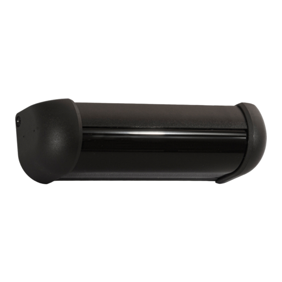
The R2E-100, including all peripheral accessories, is an active infrared, request-to-exit sensor for
applications located inside the protected premise. It is UL Listed as a request-to-exit device under the
UL 294 Standard and the CAN/ULC-S319 standard. The request-to-exit device is rated a "class 1" as
per the CAN/ULC-S319 standard.
The R2E-100 is designed to mount on or above a door header so that its detection pattern is placed
precisely in front of the door handle. In this scenario, when the user reaches for the door handle to exit,
the electronic locking (EL) device is released, and the person can exit. The active infrared detection curtain
of R2E-100 is well defined to keep the door secure, while rejecting parallel traffic and objects slid under the door.
The detection distance, or range, of the sensor is adjustable from 20 to 48 inches.
The R2E-100 Re-lock Mode can be selected to run in timer mode or door position mode. In timer mode, the relay hold-time will
control when the security device is re-locked, and it is adjustable from 0.5 to 60 seconds. In addition, the timer mode features selectable sub-
modes of operation, re-starting mode (the relay hold time will not expire as long as the sensor is in detection) or non-re-starting mode (the relay will remain active
for only the adjusted relay hold time). In door position mode, a door position switch connected to the door position switch input on the R2E-100 will control when
the door is re-locked. The door position mode also has an advanced re-locking feature that is selectable as 10 or 30 seconds. For instance, if the sensor has
gone into detection but the door has not been opened, the R2E-100 will re-lock the door and become secure again.
The R2E-100's relay output consists of two Form "C" contacts that can be wired as normally-opened or normally-closed. Also, with the R2E-100, there is no
need for any additional surge protection in the wiring of the EL device to the relay, as surge protection is already built into the sensor. This built-in protection
eliminates the need for any additional components.
The R2E-100 also contains an alarm that can be activated to sound when the door is open or when the El device is released, depending upon the sensor's
mode. The alarm's volume can also be adjusted or turned off.
Finally, the R2E-100 provides for 3 DRY auxiliary inputs: a push button or other request to exit device, a card reader or other request to enter device, and a
door position switch.
2 Specifications
DESCRIPTION
Detector Type
Supply Voltage
Current Consumption
Temperature
Humidity
Detection Distance (Range)
Relay
Relay Hold Time
Sounder
Indicator LEDs
REX Input
Card Reader Input
Door Position Switch Input
Dimensions
Material
Housing Color
Wiring Interface
Certifications
©BEA
©BEA
| Original Instructions
| Original Instructions
75.5644.09 R2E-100 20181009
75.5644.09 R2E-100 20181009
ACTIVE INFRARED, REQUEST-TO-EXIT SENSOR – DUAL RELAY OUTPUT
SPECIFICATION
Active, focused Infrared
12 – 24 VAC/VDC ±10%, 60 Hz
155 mA (sounder off) / 200 mA (sounder max volume)
-20 – 120°F (-29 – 49°C)
For UL Listed installations, the temperature range is 32 – 120°F (0 – 49°C).
0 – 93% non-condensing for ULC-S319 installations
0 – 85% non-condensing for UL-294 Listed installations
Potentiometer adjusted from 20 – 48"
Two Form "C" contact sets
rated for 1.3A @ 24 VAC / 1.3A @ 30 VDC
0.6pf (Power Factor)
Potentiometer adjusted from 0.5 – 60 seconds
85 dB max with adjustable volume
Green, red, yellow, orange
DRY Contact, normally-opened (NO)
DRY Contact, normally-closed (NC) – Can be disabled/enabled via DIP
DRY Contact, normally-opened (NO) – Can be disabled/enabled via DIP
6 7/10" (W) × 2" (H) × 1 7/10" (D) (174.63 mm × 51 mm × 47.63mm)
Plastic (ABS and PC)
Black
JST (14-pin), 4' cable
UL/ULC 294/S319, FCC Part B
R2E-100
USER'S GUIDE
Page 1 of 10
Page 1 of 10
Advertisement
Table of Contents

Related Manuals for BEA R2E-100


Summary of Contents for BEA R2E-100
- Page 1 The alarm’s volume can also be adjusted or turned off. Finally, the R2E-100 provides for 3 DRY auxiliary inputs: a push button or other request to exit device, a card reader or other request to enter device, and a door position switch.
-
Page 2: Pre-Installation Check
Remove only the right end cap from the R2E-100 (Picture 1). It is attached by one Phillips head screw. Remove the lens from R2E-100 by simply sliding it out at the right end of the housing approximately a 1/4 inch and then gently pull the lens down and away from the housing (Picture 2). -
Page 3: Electrical Installation
Install R2E-100 with Lens Cover Facing Down Toward Door Handle If the R2E-100 is mounted directly to door header and cabling is to pass directly into header, drill a 3/8” hole next to the sensor’s right end cap to allow wire passage into header. The wire passage hole should be in a location that aligns with the cut-out in the housing. - Page 4 UL/ULC SPECIFIC NOTES: For UL 294 Listed installations, the R2E-100 should only be powered by a UL 294 Listed, power limited power supply, as well as connected to a UL Listed electronic locking (EL) device and associated access control hardware.
-
Page 5: Mechanical Adjustment
5º position, but may be reduced to a 0º position or increased to a 10º position. The greater the angle, the farther from the door handle the pattern will be. The 0º angle should only be used when the R2E-100 is mounted to a BodyMount block or to a door soffit that extends out past the face of the door handle. -
Page 6: Indicator Leds
9 Sensor Adjustment (cont.) DIP Switch Settings 8 position DIP (Picture 9). DIP 1: R2E-100 will enter either fail-safe (ON) or fail-secure (OFF) if stuck in constant detection (masked). DIP 2: Re-lock mode is door position mode (ON) or timer mode (OFF). * DIP 3: Door position mode advanced re-lock time is 10 seconds (ON) or 30 seconds (OFF). -
Page 7: Complete Installation
Patent Pending BEA INSTALLATION/SERVICE COMPLIANCE EXPECTATIONS BEA Inc., the sensor manufacturer, cannot be held responsible for incorrect installations or inappropriate adjustments or the sensor/device; therefore, BEA Inc. does not guarantee any use of the sensor outside its intended purpose. BEA Inc. strongly recommends that installation and service technicians be AAADM-certifi ed for pedestrian doors, IDA-certifi ed for doors/gates, and factory-trained for the type of door/gate system. - Page 8 APPENDIX 1 ©BEA ©BEA | Original Instructions | Original Instructions 75.5644.09 R2E-100 20181009 75.5644.09 R2E-100 20181009 Page 8 of 10 Page 8 of 10...
- Page 9 APPENDIX 2 ©BEA ©BEA | Original Instructions | Original Instructions 75.5644.09 R2E-100 20181009 75.5644.09 R2E-100 20181009 Page 9 of 10 Page 9 of 10...
- Page 10 Installation Tips The R2E-100 active infrared pattern is made up of two narrow, side-by-side detection zones that project at slightly offset angles. See Figure 1 for an illustration of the two detection zones in a typical installation. Figure 2 shows the relative position of the two zones or “spots” at a distance of 48”...