
Related Manuals for Culligan M2 Series


Summary of Contents for Culligan M2 Series
- Page 1 Cat. No. 01023095 Rev. C 05/03/13 DCO # 013581 Installation, Operation and Service Instructions CULLIGAN ® Series M2 Reverse Osmosis Water Treatment Systems Models from 2011 Firmware Version ©2013 Culligan International Com pa ny...
- Page 2 We encourage Culligan users to learn about Culligan products, but we believe that product knowledge is best obtained by consulting with your Culligan dealer. Untrained individuals who use this manual assume the risk of any resulting property damage or personal injury.
-
Page 3: Table Of Contents
Installation Operation Instructions Culligan ® Series M2 Reverse Osmosis Water Treatment Systems Models From 2011 Contents Initial Startup..............System Operating Information ......... Introduction ................ Service and Maintenance ..........Features ................Flow Diagram ..............Series M2 Specifications ........... GBE RO Controller Wiring .......... - Page 4 This page intentionally left blank. Cat. No. 01023095 Culligan® Series M2 Reverse Osmosis...
-
Page 5: Introduction
Introduction Read this Manual First Before you operate the Culligan® Series M2 reverse osmosis systems, read this manual to become familiar with the device and its capabilities. Culligan Series M2 reverse osmosis systems are designed to meet the needs of applications for high quality water. This ®... -
Page 6: Features
The M2 Series Reverse Osmosis systems are the direct result of Culligan’s long time experience in membrane applica- tions around the world. From process water for any size business to treating water for an entire city, Culligan has the knowledge and the range of products you need to get the job done. - Page 7 An optional modem and monitoring service can be used to remotely monitor the RO performance over time. This service can also be used to alert the customer and the Culligan dealer in the event that an alarm or error condition occurs.
- Page 8 • Daily average gallons of product water produced This data, once converted from a text stream, can easily be imported to an excel spreadsheet and the data logged can then be graphed and trended. Cat. No. 01023095 Culligan® Series M2 Reverse Osmosis...
-
Page 9: Series M2 Specifications
Series M2 Specifications NOTE The International Specifications for M2 are in Appendix A on page M2-2 M2-3 M2-4 M2-5 M2-6 Nominal Capacity, GPD* 4000 5800 7500 9000 10000 Dimensions, Series M2 Units Width - in [mm] 25.8 [655.3] Depth - in [mm] 29.3 [744.2] Height - in [mm] 52.6 [1336]... -
Page 10: Unit Configurations
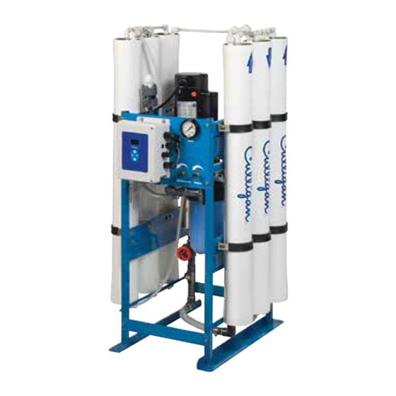
“M2 RO Parts Diagrams and Lists” on page 73 for a list of component part numbers. Membranes Product Flow Meter Pump Feed Pressure RO Controller (GROC) Recirculation Control Waste Control Pump Prefilter Figure 1. M2 RO front view. Cat. No. 01023095 Culligan® Series M2 Reverse Osmosis... -
Page 11: Ro Installation
RO Installation Unpacking the RO This manual, the warranty, and registration card are packed in the control assembly box. Please complete the registration card and mail it promptly. NOTICE Examine each unit component carefully to check for loose or damaged parts. Report any apparent or concealed shipping damage to the freight carrier immediately. - Page 12 CENTER PORT OF END CAPS OFF-CENTER PORT OFF-CENTER PORT OF END CAPS OF END CAPS CENTER PORT OF END CAPS OFF-CENTER PORT OF END CAPS Figure 2. Module Tubing, two to four membranes. Cat. No. 01023095 Culligan® Series M2 Reverse Osmosis...
- Page 13 CENTER PORT OF END CAPS OFF-CENTER PORT OFF-CENTER PORT OF END CAPS OF END CAPS CENTER PORT CENTER PORT OF END CAPS OF END CAPS OFF-CENTER PORT OF END CAPS Figure 3. Module Tubing, five or six membranes. RO Installation Cat.
- Page 14 4) with the addition of a pressure switch which needs to be wired to the control panel (see page 72 for RO standard wiring). A pressurized water storage kit is available under part number D1018976. Cat. No. 01023095 Culligan® Series M2 Reverse Osmosis...
- Page 15 Non-Pressurized Product Water Storage Tank Connect the product tubing to a bulkhead fitting at the top of the storage tank. CAUTION! The highest point of the tubing should not be higher than four feet above the top of the reverse osmosis modules, or the elements may be damaged. Depending on the type of application, a level control may be required to turn the unit off when the storage tank is full.
-
Page 16: Electrical Installation
To open the control panel, loosen the two screws and carefully open the cover by rotating it to the left. Plugged Feed Flow Meter Product TDS Motor Cord Solenoid Valve 1 Optional for Fast Incoming Power Flush Kit 01025703 Product Flow Meter Pressure Switch Figure 5. M2 controller connections. Cat. No. 01023095 Culligan® Series M2 Reverse Osmosis... -
Page 17: Groc Board Layout
GROC Board Layout Series Global RO Controller Circuit Board Layout—Front NOTE For a detailed explanation on wiring the circuit boards, refer to “GBE RO Controller Wiring” on page 72 OLED display Battery CR2032 (Postitive Side Up) Keypad connector Figure 6. GROC circuit board layout—front Modem Connectors Remote Display... - Page 18 For Series M2 RO Systems, make sure the voltage selector switch is set at 230 VAC. Voltage Selector Switch Transformer Fuse 315mA Power 115V-230VAC 50-60Hz Fuse 5A Relays Figure 8. GBE 115V/230V relay board. Cat. No. 01023095 Culligan® Series M2 Reverse Osmosis...
-
Page 19: Groc Programming
GROC Programming Program Data Input There are a few items to note that can make programming the Culligan Global Reverse Osmosis Controller (GROC) ® easier: Slew Rates This term refers to the speed at which the display moves through the input of material. For ex- ample, holding down the up arrow key for (5) seconds when inputting minutes for Time of Day will cause the minutes to pass in (10) minute blocks of time. -
Page 20: Menu And Key Navigation
CAUTION! Use the only to scroll through the menu settings. Do not use to perform scrolling. Improper use of might cause the controller to reset certain functions. Cat. No. 01023095 Culligan® Series M2 Reverse Osmosis... -
Page 21: First Time Set Up
The S/N, firmware, and date displayed in this manual are examples only. NOTE If this unit will be installed with a modem, it is required that this electronic serial number be reported to Culligan on the IQR form. Setting Up Date and Time The screen displays the month setting. Press... - Page 22 US INCH US INCH and then to change the value and complete the METRIC first-time setup. NOTE This setting does not automatically change to metric if you select a language other than English. Cat. No. 01023095 Culligan® Series M2 Reverse Osmosis...
- Page 23 Completed First Time Setup STARTING When the setup is complete, the circuit board microprocessor automatically calcu- JAN-01-12 12:01P lates the water conditioner capacity. The screen displays the initializing status and the current date and time, and then transitions to the home screen. RUNNING The screen displays the current state of the RO system (RUNNING or OFFLINE) JAN-01-12 12:01P...
-
Page 24: Basic Operation
(select NO to cancel the command and return to the main menu). OFFLINE JAN-01-12 12:01A The screen displays the main menu. Press repeatedly to return to the home screen, which displays the operational status (OFFLINE). Cat. No. 01023095 Culligan® Series M2 Reverse Osmosis... -
Page 25: Setup
Setup After completing the first time setup for the RO, you must also complete the system setup for flush modes, accessories, and error limits before completing the initial startup. Flow Meter K-Factor setting is required during setup. All other RO settings are optional depending on the accessories installed. - Page 26 SETUP menu. >4) SETUP 1) TIME/DATE >2) LANGUAGE Press to select 2)LANGUAGE. The screen displays the last selected lan- 3) POWERON MODE guage of the RO controller. 4) FLUSH MODES Cat. No. 01023095 Culligan® Series M2 Reverse Osmosis...
- Page 27 LANGUAGE ENGLISH Press and then to change the display to your preferred language. 1) TIME/DATE >2) LANGUAGE The screen displays the setup menu in the selected language of the RO controller. 3) POWERON MODE 4) FLUSH MODES Set Up Power On Mode RUNNING JAN-01-12 12:01P...
- Page 28 The Permeate Flush solenoid valve is wired to the AUX board on the GBE RO controller at terminal AUX4 (G1). The solenoid valve must be 24 Volt. Figure 10. RO permeate flush. Cat. No. 01023095 Culligan® Series M2 Reverse Osmosis...
- Page 29 At shutdown, the pump turns off and SV1 closes. Then fast flush solenoid valve SV2 and permeate valve SV3 open for a programmed number of minutes. During this time, RO produt water stored either in an elevated atmospheric tank or in a pressurized storage tank floods through the pump and the feed side of the membrane, and then SV2 and SV3 close.
- Page 30 13. If time trigger mode is set to ON, the screen displays the flush 1–24 interval setting. Press and then to change HOURS the value and then return to the Flush Mode menu. Cat. No. 01023095 Culligan® Series M2 Reverse Osmosis...
- Page 31 Screen Display Range Procedure FLOW TRIG MODE 14. The screen displays the Flow Trigger Mode setting. Press and then to change the value and see the flow trigger mode settings. 15. The screen displays the Flow Trigger Mode setting. If the sys- FLOW TRIG MODE tem is running, the unit will flush after generating a specified amount of reverse osmosis water.
-
Page 32: Accessories
Hang the remote monitor on the two screws. Plug into a 120V outlet. Disconnect power to the RO unit. Open the control. Cat. No. 01023095 Culligan® Series M2 Reverse Osmosis... -
Page 33: Cat. No.
Figure 12. RF board location on GROC board. Back of GBE Board RF Board (note orientation) Install RF board into unit controller. Line up pins in RF board and press firmly into black connectors. Note ori- entation of RF board (see Figure 12).Make sure the RF board is fully seated into all of the sockets. Reconnect power. - Page 34 Use this setting to select the correct radio frequency. Do not change the RF fre- quency for North America installations.. RUNNING JAN-01-12 12:01P Press to save the settings and return to the home screen. Cat. No. 01023095 Culligan® Series M2 Reverse Osmosis...
- Page 35 Check Signal Strength Between the GBE RO Controller and Remote Check the signal strength once the RO controller and wireless remote are set up. RUNNING JAN-01-12 12:01P From the default home screen, press . The screen displays the main menu. 1) GO TO RUNNING 2) GO TO OFFLINE Press...
- Page 36 (part number 01020747) into the socket on the back of the board. Make sure that all of the pins in all four connec- tors are aligned and make sure the modem is fully seated into all of the sockets. Figure 13. Back of GROC board. Cat. No. 01023095 Culligan® Series M2 Reverse Osmosis...
- Page 37 Installing the Modem In the Remote Open the remote monitor housing by removing the two screws and squeezing the sides of the monitor housing slightly. Insert the modem board (P/N 01020747) into the socket on the back of the remote board (see Figure 14). Make sure that all of the pins in all four connectors are aligned and make sure the modem is fully seated into all of the sockets.
- Page 38 Monthly & Error CALL TIME 12:00AM– 4:30AM 11:30PM Press and then to specify when the RO controller sends data via modem. The time changes in increments of 30 minutes. Cat. No. 01023095 Culligan® Series M2 Reverse Osmosis...
- Page 39 (as opposed to installed in the remote control) then this testing process will also check to see if there is an updated version of firmware available on the Culligan servers. After conducting a phone line test, it is important to verify that the new time and date settings on the controller are correct.
- Page 40 From the Setup menu, press to select 2)MODEM SETUP. The screen dis- >2)MODEM SETUP plays the modem settings. Use these to set up the communication between the wireless remote and the Culligan servers. GBE RO Controller Modem Settings (on Remote) Screen Display Range...
- Page 41 Flow Meters There are two flow meters on the M2 RO system, the feed flow meter (FM1) and the product flow meter (FM2). Connect the wires of both flow meters to the GBE board using the 4 - pin connections provided. The feed flow meter con- nects to FM1 (J11) and the product flow meter connects to FM2 (J12).
- Page 42 5)ACCESSORIES. The screen displays the ac- 4) FLUSH MODES cessories menu. >5) ACCESSORIES 1) WIRELESS REM 2) MODEM Press to select 3)FLOW METERS. The screen displays the flow meter >3) FLOW METERS settings. 4) SWITCH INPTS Cat. No. 01023095 Culligan® Series M2 Reverse Osmosis...
- Page 43 Flow Meter Settings Screen Display Range Changing the Setting FLOW METERS The screen displays the installation status of the flow meter. Press Installed INSTALLED to change the state to installed if a flow meter is in- Not Installed stalled in the RO system. FM1 K FACTOR 80.0 Press...
- Page 44 Disconnect electrical power source, then check the wiring and replace the switch, if necessary. 15. Open the inlet water supply valve. The unit should restart. 16. If connected, test the storage tank level control shutdown and the pretreatment lockout function. Cat. No. 01023095 Culligan® Series M2 Reverse Osmosis...
- Page 45 Switch Inputs Low Pressure Switch at the end of Display says display says the “SV1 Delay time; “OFFLINE” “STARTING”, the unit checks or “STANDBY”; then the the pressure then the SV1 output switch input; SV1 output turns ON; If the pressure is ok, is OFF;...
- Page 46 From the default home screen, press . The screen displays the main menu. 1) GO TO RUNNING 2) GO TO OFFLINE Press to scroll to 4) SETUP. 3) INFORMATION Press to select the SETUP menu. >4) SETUP Cat. No. 01023095 Culligan® Series M2 Reverse Osmosis...
- Page 47 2) LANGUAGE 3) POWERON MODE Press to select 5)ACCESSORIES. The screen displays the ac- 4) FLUSH MODES cessories menu. >5) ACCESSORIES 1) WIRELESS REM 2) MODEM Press to select 4)SWITCH INPTS. The screen displays the switch 3) FLOW METERS inputs settings. >4) SWITCH INPTS Switch Inputs Settings Screen Display...
- Page 48 Please do not change this value unless you are told to do so by Cul- 0.025 ligan Rosemont. This value changes the slope used to interpret the temperature. RUNNING JAN-01-12 12:01P Press to save the settings and return to the home screen. Cat. No. 01023095 Culligan® Series M2 Reverse Osmosis...
- Page 49 Alarm Relay Board The GBE RO controller board offers support for the Culligan Alarm Relay board (P/N 01022238). See Figure 19. To use the alarm relay board, install it onto the back of the GBE RO controller board. See Figure 20.
- Page 50 “error condition.” Alternatively, the Alarm Signal Output contact terminals can be wired to a customer supplied PLC or SCADA system to provide an indication to the customer of the status of the GBE RO controller-controlled equipment. Cat. No. 01023095 Culligan® Series M2 Reverse Osmosis...
- Page 51 Multiple Unit ROs The GBE RO controller supports two multi-unit modes: Two Pass and Alternating. When in two-pass or alternating mode, the system is configured to support two GBE RO controllers that are connected to- gether using the communication cable (P/N 01016327). See Figure 22. One of these boards is set as the master, control- ling the operations of the other unit, also known as the slave.
- Page 52 RO have its own independent dry contact closure signal from the pre-treatment system wired to the individual GROC controllers. When either unit is the “running” unit, it operates as a single unit. Cat. No. 01023095 Culligan® Series M2 Reverse Osmosis...
- Page 53 COMMUNICATION CABLE (P/N 01016327) JUMPER 1 2 3 NOTE: MAKE SURE TO COVER PINS 1 & 2 ON THE JUMPERS WHEN CONNECTING TWO UNITS TOGETHER. Figure 23. Wiring for two-pass and alternating mode. Figure 24. RO duplex alternating plumbing. Accessories Cat.
- Page 54 This screen shows the status of the Slave unit/ Second Pass’s Motor ON motor. Motor OFF The following screen shots can ONLY be viewed on the Master unit/ First Pass. 1)GO TO RUNNING 2)GO TO OFFLINE Press to select 3)INFORMATION. >3)INFORMATION 4)SETUP Cat. No. 01023095 Culligan® Series M2 Reverse Osmosis...
- Page 55 Information Settings for a Two-Pass RO NOTE When you any information screen, it will stay on the display until changed by the operator. Screen Display Range Procedure FFLOW 0.00 GPM This screen lists the information for both units. FFLOW is the feed PFLOW 0.00 GPM flow on the Master unit/ First Pass.
- Page 56 24-month “snapshots”. This historical data is available even if the modem option is not used. If the historical data has been cleared, the screen displays NONE. Cat. No. 01023095 Culligan® Series M2 Reverse Osmosis...
- Page 57 Screen Display Range Procedure CLEAR HIST DATA? Press to change the setting to YES, which clears historical data from the screen. Press to return to the main menu. Erase this data ONLY when replacing the membranes. SV3 (Solenoid Valve) Mode/TDS Target Solenoid valve SV3 is physically connected to the mini-aux board AUX4.
- Page 58 SV3 to meet the target TDS. If the target TDS 5–60 is not met by the end of the TDS target time, the RO system will MINUTES generate the error “PRODUCT TDS TOO HIGH” and go out of service. Cat. No. 01023095 Culligan® Series M2 Reverse Osmosis...
-
Page 59: Initial Startup
Depending on the feed water quality, it may be possible to operate the unit with a lower concen- trate flow rate, which would decrease operating costs. Refer to the printout from the Culligan® CAAP® (Computer Aided Application Program) software, which indicates maximum allowable recovery. - Page 60 If any changes are noticed, the product flow should be normalized to determine if cleaning is required (see Product Flow Calculations on the next page). Cat. No. 01023095 Culligan® Series M2 Reverse Osmosis...
- Page 61 100 gpd, or 18% (100/570) = 0.18. The elements should be cleaned. 10. If the problem cannot be corrected with the troubleshooting guide and assistance is required, please have the following information available when calling the Culligan dealer: • Product flow rate • Concentrate flow rate...
-
Page 62: System Operating Information
PS1 = OPEN PTLO = OPEN Indicates whether the pressure switch, pretreatment lockout, high FS HI = OPEN float switch or low float switch is open or closed (if installed). FS LO = OPEN Cat. No. 01023095 Culligan® Series M2 Reverse Osmosis... - Page 63 Screen Display Range Procedure TOTAL FEED WATER Displays the total number of incoming untreated water gallons since the unit was put into service. GALLONS TOTAL PROD WATER Displays the total number of product water gallons since the unit was put into service. GALLONS PUMPING TIME Displays the total number of hours the unit has been in service...
-
Page 64: Service And Maintenance
Service and Maintenance Serial Numbers The Culligan RO units have a serial number located directly behind the electronic controller on the side panel. Do not remove or destroy these serial number labels. They must be referenced if you require repairs or parts replacement under warranty. - Page 65 Error Codes When the G Series RO Controller encounters an error, the screen displays a message. Press to scroll to the error message. STANDBY JAN-01-12 1:55P No Remote Signal These error conditions initiate an alert that is sent to the dealership if the telemetry (modem) options are set up, and then the RO will shut down.
- Page 66 The wireless remote is not indicating a dialup connection. An optional wireless re- NO DIAL TONE mote must be installed to see this message. LOW BATTERY The battery strength is below specification level. Cat. No. 01023095 Culligan® Series M2 Reverse Osmosis...
- Page 67 Technical Service Specialist at Culligan in the value(s). Rosemont. If the data sheet is not available, contact Culligan and pro- vide the unit serial number. The values will be looked up. Calibrating the TDS Probe The probes can be easily field calibrated using a calibrated handheld TDS meter. Disconnect the probe from the RO plumbing and submerge it into a solution of known TDS.
- Page 68 DO NOT use a petroleum-based lubricant, because it will damage the synthetic rubber and the membrane. Make sure the brine seal is located in the direction of the incoming feed to that vessel according to the flow arrow and the original membrane orientation. Cat. No. 01023095 Culligan® Series M2 Reverse Osmosis...
- Page 69 Lubricate the O-ring on the end plugs with a silicone-based lubricant or use a mixture of 70% glycerin and 30% water. Re-install the end plugs in to the vessels same as the original orientation. Reinstall the retaining clips. Refer to “Initial Startup”...
- Page 70 Please note that if the product flow rate has increased (with no increase in temperature or pressure) the likely reason is damage to the membrane, which cannot be repaired by cleaning. Cat. No. 01023095 Culligan® Series M2 Reverse Osmosis...
- Page 71 Once the foulant has been identified, choose the recommended cleaning chemical(s) from Table 9. Membrane Problem Cleaning Chemical Hardness Scale Hydrochloric acid, phosphoric acid Iron Hydrochloric acid, phosphoric acid Silt Phosphoric acid and sodium hydroxide Biofouling Phosphoric acid and sodium hydroxide Table 9.
- Page 72 If the cleaning was for silt or biofouling, take a 250 ml sample of phosphoric acid solution and carefully add sodium hydroxide until the pH is at least 12. If the solution turns cloudy, it contains hardness and/or iron. Cat. No. 01023095 Culligan® Series M2 Reverse Osmosis...
- Page 73 Discard the contaminated acid and prepare a fresh 30 gallons of phosphoric acid solution.Add sodium hydroxide to the phosphoric acid solution. The pH of the solution should be increased to 11.0-11.5. NOTE The result is an alkaline solution of tri-sodium phosphate (TSP), a common ingredient in detergents. If the solution remains clear, then direct the concentrate tubing to drain, then choose GO TO RUNNING from the main menu.
- Page 74 Compare these values with the “new” and “now” values to determine if cleaning has been successful. If clean- ing has not been successful, contact the service department at Culligan International Company for suggestions on alternate cleaning chemicals. If cleaning has been successful, note which chemicals were effective. Use the same chemical(s) when the unit is cleaned again.
-
Page 75: Flow Diagram
Flow Diagram Process Flow Diagram Flow Diagram Cat. No. 01023095... -
Page 76: Gbe Ro Controller Wiring
GBE RO Controller Wiring GROC Basic Sub-Panel Wiring Diagram NOTE For Series M2 RO Systems, make sure the voltage selector switch is set at 230 VAC. Figure 27. GBE RO Controller Basic sub-panel wiring. Cat. No. 01023095 Culligan® Series M2 Reverse Osmosis... -
Page 77: M2 Ro Parts Diagrams And Lists
M2 RO Parts Diagrams and Lists Series M2 Major Components and Water Connections, 208-230V/ 60 Hz, U.S. Membrane Product Assemblies Flow Meter Pump Pressure Gauge Global RO Controller Waste and Pump/Motor Recirculation Valves 13 45 Prefilter Throttling Valve Figure 28. M2 RO front view. - Page 78 — Cord, Motor Power, M2 01022319 Product Flow Pump/Motor Meter Inlet Flow Meter Figure 30. M2 right side view w/o membrane housings. Figure 31. M2 back view without pump and cross brace. Cat. No. 01023095 Culligan® Series M2 Reverse Osmosis...
- Page 79 Feed Assembly, 208-230V/ 60 Hz, U.S. Figure 32. M2 feed assembly. Item Part No. Description Quantity — 01021939 PIPING ASSEMBLY M2 FEED 01017302 SOLENOID VALVE, 3/4",NC,220V/60HZ — NIPPLE,3/4X3,PVC SCH.80,PE — NIPPLE,3/4X4,PVC SCH.80,PE — Nipple,3/4x2,PVC Sch.80,TOE — Nipple,3/4x2-1/2,PVC Sch.80,TOE — Tee,3/4",Socket,PVC Sch.80 —...
- Page 80 M2 product piping assembly. Item Part No. Description Quantity — 01021941 Piping Assembly Product — Tee, Threaded, .50 PVC Sch.80, NPT — Nipple,1/2xClose,PVC Sch.80,TBE — Nipple,1/2x5,PVC Sch.80,TBE — Fitting,Male Adapter,J G, PP011624W, 1/2" Cat. No. 01023095 Culligan® Series M2 Reverse Osmosis...
- Page 81 Concentrate Piping Sub-Assembly, 208-230V/ 60 Hz, U.S. NOTE: Cut Tubing to 2” NOTE: Cut Tubing to 2.5” NOTE: Cut Tubing to 2.5” Figure 34. M2 concentrate piping sub-assembly. Item Part No. Description Qty. — 01021940 Piping Assembly M2 Concentrate 01021539 Valve,Needle,1/2"...
- Page 82 01023073 End Plug Assembly, 4" P1021848 O-Ring Head Seal 4”, 20 pack Housing comes with everthing, except the membrane. Each vessel requires two (2) individual o-rings NOT two (2) packages of o-rings. Cat. No. 01023095 Culligan® Series M2 Reverse Osmosis...
- Page 83 .75 x .75 NPT Fitting, Barbed — Elbow, 3/4", TxT, PVC Sch.80 — Nipple, 3/4x3, PVC Sch.80, TBE — Decal, Flow Arrow — Decal, Culligan Script 01024102 Saddle Strap Kit (2 straps, 2 saddles, 4 screws) M2 RO Parts Diagrams and Lists Cat. No. 01023095...
- Page 84 Fitting, Union Tee, 1/2T, PI 01008007 Element RO 4" Dia. x 40" Filmtec, TW30XLE-4040 — Decal, Flow Arrow — Decal, Culligan Script 01024102 Saddle Strap Kit (2 straps, 2 saddles, 4 screws) Cat. No. 01023095 Culligan® Series M2 Reverse Osmosis...
- Page 85 Elbow, 3/4", TxT, PVC Sch.80 — Nipple, 3/4x3, PVC Sch.80 TBE 01008007 Element RO, 4" Dia x 40" Filmtec, TWO30XLE-4040 — Decal, Culligan Script — Decal, Flow Arrow 01024102 Saddle Strap Kit (2 straps, 2 saddles, 4 screws) M2 RO Parts Diagrams and Lists...
- Page 86 Fitting, Union Elbow, 1/2T, PI 01008007 Element RO, 4" Dia x 40" Filmtec, TWO30XLE-4040 — Decal, Culligan Script — Decal, Flow Arrow 01024102 Saddle Strap Kit (2 straps, 2 saddles, 4 screws) Cat. No. 01023095 Culligan® Series M2 Reverse Osmosis...
- Page 87 Controller Sub-Assembly, 208-230V/ 60 Hz, U.S. Figure 40. M2 Controller front panel. Figure 41. M2 Controller main and auxiliary boards. M2 RO Parts Diagrams and Lists Cat. No. 01023095...
- Page 88 Figure 42. M2 Controller cords and miscellaneous parts. Figure 43. M2 Controller relay board. Cat. No. 01023095 Culligan® Series M2 Reverse Osmosis...
- Page 89 M2 Global RO Controller Parts, 208-230V/ 60 Hz, U.S. Item Part No. Description 01024371 Controller, M2 Series Matrix Solutions 01024191 Enclosure,GBE Small 01021527 Circuit Board,Main GBE,Commercial RO 01023100 GBE 115/230V RELAY BOARD 01022953 CABLE, 22 AWG, 2 CONDUCTOR W/MTA100 CONN —...
- Page 90 Item Part No. Description 01021586 Remote Display Assembly, RO - 915 MHz 01025686 Circuit Board, Remote, English, Replacement 01020750 Circuit Board, RF, GBE, 915 MHz 01020611 Power Supply, Switching, Wall Mount, 100VAC-240VAC Cat. No. 01023095 Culligan® Series M2 Reverse Osmosis...
-
Page 91: Appendix A Series M2 International
Appendix A Series M2 International Series M2 International Specifications M2-2 M2-3 M2-4 M2-5 M2-6 Nominal Capacity, GPD* 3360 4870 6300 7560 8400 Dimensions, Series M2 Units Width - in [mm] 25.8 [655.3] Depth - in [mm] 29.3 [744.2] Height - in [mm] 52.6 [1336] Operating Weight lb [kg] 198 [89.1]... - Page 92 Gauge Global RO Controller Waste and Pump/Motor Recirculation Valves 13 45 Prefilter Throttling Valve Figure 45. M2 RO front view. Left Side View Right Side View Figure 46. M2 RO side views. Cat. No. 01023095 Culligan® Series M2 Reverse Osmosis...
- Page 93 M2-4 M2-5 M2-6 — RO System , M2 01023855 01023856 01023857 01023858 01023859 Pump/Motor Cent 1.0HP 220-240, 1 ph, 50 Hz 01023882 Controller, M2 Series 01024371 Piping Feed 01021939 Piping Product 01021941 Piping Concentrate 01021940 Membrane Array, 2-1 01021927 01021927...
- Page 94 Elbow,3/4",TxT,PVC Sch.80 — ADAPTER HOSE BARB 3/4" X 3/4" NPTE — Fitting,Male Adapter,1/2Tx1/2NPTE,PI 01021543 Check Valve — Nipple,1/2xClose,PVC Sch.80,TBE — Fitting,Stem Elbow,1/2Tx1/2Stem,PI — Nipple,3/4x3, PVC Sch.80,TOE — Nipple, 3/4x3-1/2, PVC Sch.80, TOE Cat. No. 01023095 Culligan® Series M2 Reverse Osmosis...
- Page 95 Product Assembly, 220V/ 50 Hz, International Figure 50. M2 product piping assembly. Item Part No. Description Quantity — 01021941 Piping Assembly Product — Tee, Threaded, .50 PVC Sch.80, NPT — Nipple,1/2xClose,PVC Sch.80,TBE — Nipple,1/2x5,PVC Sch.80,TBE — Fitting,Male Adapter,J G, PP011624W, 1/2" Cat.
- Page 96 Item Part No. Description Qty. — 01021940 Piping Assembly M2 Concentrate 01021539 Valve,Needle,1/2" Brass — Fitting,Male Adapter,1/2Tx1/2NPTE,PI — Fitting,Stem Elbow,1/2Tx1/2Stem,PI — Fitting,Union Tee,1/2T,PI 00901801 Tubing,1/2",PE,Natural — — Fitting, Union Elbow, 1/2T, PI Cat. No. 01023095 Culligan® Series M2 Reverse Osmosis...
- Page 97 Membrane Vessel, 220V/ 50 Hz, International SCREWS RETAINING RINGS END CAP O-RINGS NOTE: 1 Does NOT Include 2 Figure 52. M2 membrane vessel. Item Part No. Description Per Vessel 01021540 Housing, Filter, Wave Cyber FRP 4" End Port 01024290 Membrane, CSM, 4"x40" 01023073 End Plug Assembly, 4"...
- Page 98 .75 x .75 NPT Fitting, Barbed — Elbow, 3/4", TxT, PVC Sch.80 — Nipple, 3/4x3, PVC Sch.80, TBE — Decal, Flow Arrow — Decal, Culligan Script 01024102 Saddle Strap Kit (2 straps, 2 saddles, 4 screws) Cat. No. 01023095 Culligan® Series M2 Reverse Osmosis...
- Page 99 Fitting, Union Elbow, 1/2T, PI — Fitting, Union Tee, 1/2T, PI 01008007 Element RO 4" Dia. x 40" Filmtec, TW30XLE-4040 — Decal, Flow Arrow — Decal, Culligan Script 01024102 Saddle Strap Kit (2 straps, 2 saddles, 4 screws) Cat. No. 01023095 Series M2 International...
- Page 100 Nipple, 3/4x3, PVC Sch.80 TBE 01008007 Element RO, 4" Dia x 40" Filmtec, TWO30XLE-4040 — Decal, Culligan Script — Decal, Flow Arrow 01024102 Saddle Strap Kit (2 straps, 2 saddles, 4 screws) Cat. No. 01023095 Culligan® Series M2 Reverse Osmosis...
- Page 101 Fitting, Union Tee, 1/2T, PI — Fitting, Union Elbow, 1/2T, PI 01008007 Element RO, 4" Dia x 40" Filmtec, TWO30XLE-4040 — Decal, Culligan Script — Decal, Flow Arrow 01024102 Saddle Strap Kit (2 straps, 2 saddles, 4 screws) Cat. No. 01023095...
- Page 102 Controller Sub-Assembly, 220V/ 50 Hz, International Figure 57. M2 Controller front panel. Figure 58. M2 Controller main and auxiliary boards. Cat. No. 01023095 Culligan® Series M2 Reverse Osmosis...
- Page 103 Figure 59. M2 Controller cords and miscellaneous parts. Figure 60. M2 Controller relay board. Cat. No. 01023095 Series M2 International...
- Page 104 M2 Global RO Controller Parts, 220V/ 50 Hz, International Item Part No. Description 01024371 Controller, M2 Series Matrix Solutions 01024191 Enclosure,GBE Small 01021527 Circuit Board,Main GBE,Commercial RO 01023100 GBE 115/230V RELAY BOARD 01022953 CABLE, 22 AWG, 2 CONDUCTOR W/MTA100 CONN —...
- Page 105 Remote Display Assembly, 220V/ 50 Hz, International Figure 61. Remote display assembly. Remote Display Assembly Parts List, 220V/ 50 Hz, International Item Part No. Description D1025674 Remote Display Assembly, RO - 869 MHz, English D1025679 Remote Display Assembly, RO - 869 MHz, French D1025680 Remote Display Assembly, RO - 869 MHz, Italian D1025681...
-
Page 106: Appendix B Basic Principles
Feed water product stream and concentrate stream. During the process of reverse osmosis, some of the water has its dissolved solids content reduced by approximately 99%. This high quality product water is sent to service Cat. No. 01023095 Culligan® Series M2 Reverse Osmosis... - Page 107 *Short term cleaning is acceptable for pH ranges between 2.0/12.0. Additional treatment is required when chloramines are present and the pH levels exceed 9.0. NOTICE In some applications, a water softener is not required. Consult an independently operated Culligan dealer for further information on these special applications. Basic Principles...
-
Page 108: Appendix C Gbe Ro Controller Menu Structure
Appendix C GBE RO Controller Menu Structure FWR**LT04 MON DD YEAR Cat. No. 01023095 Culligan® Series M2 Reverse Osmosis... - Page 109 GBE RO Controller Menu Structure Cat. No. 01023095...
- Page 110 Cat. No. 01023095 Culligan® Series M2 Reverse Osmosis...
- Page 111 FWR***LT04 MON DD YEAR GBE RO Controller Menu Structure Cat. No. 01023095...
-
Page 112: Appendix D Data Port Output
M = Date and Time. i.e. 102320111027 is Oct 23 2011 (102311) at 10:27 am (1027). Time is in 24 hr format. Electrical Connections The Culligan Data Cable Connector is terminated with a D-sub9 style female termination. The customer must provide the following pin connections:... - Page 113 The following data cable styles are available from Culligan (kits for Modbus, BACNET, and Profibus are also available from your Culligan dealer): Cable Part No. Description 01021507 USB style output cable—comes with CD-ROM which includes device drivers for Microsoft ®...
- Page 114 Sending ... Press to to send the mini report. MINI REPORT The GBE RO controller displays the message delivery status. Press to exit the Sent! screen. See Figure 65 regarding report data. Cat. No. 01023095 Culligan® Series M2 Reverse Osmosis...
- Page 115 *** MINI REPORT *** FM1 = 0.00 FM2 = 0.00 PI-PO = 0 Operational Status = OFFLINE Recovery Rate = 0.0 % Rejection Rate = 76 % Float Switch Hi = active Float Switch Low = active Total FM1 = 0 Total pump on = 0 hrs Units = Inch FM1 Meter Factor = 80.0...
-
Page 116: Appendix E Quick Programming Guide
(up to eight digits). RUNNING The “home” screen displays JAN-01-12 12:01P the RUNNING or OFFLINE Press to save the settings and return to the status of the RO system. home screen. Cat. No. 01023095 Culligan® Series M2 Reverse Osmosis... - Page 117 First Time Setup with Quality Flush and High Level Float Switch Press to select a setting. Press to change the setting. Press to save. Press to exit from a menu. Select Language Set Up Flush Modes LANGUAGE 1)GOTO RUNNING ENGLISH 2)GOTO OFFLINE Press to scroll to 4)SETUP...
- Page 118 The “home” screen displays RF FREQUENCY Select the radio frequency: JAN-01-12 12:01P the RUNNING or OFFLINE 915MHz 915MHz for North America, status of the RO system. 869 or 933 in other locations. Cat. No. 01023095 Culligan® Series M2 Reverse Osmosis...
- Page 119 Quick Programming Chart—First Time Setup with Flow Trigger Flush Press to select a setting. Press to change the setting. Press to save. Press to exit from a menu. Select Language Set Up Flush Modes LANGUAGE 1)GOTO RUNNING ENGLISH 2)GOTO OFFLINE Press to scroll to 4)SETUP Select the controller language.
-
Page 120: Appendix F Programming Log
Appendix F Programming Log Use this section to record the program settings for this system. Circle or enter the observed value. Make additional copies to keep on file near the installation and with your local Culligan dealer. Program Date: ___________ Installer: _____________________________... -
Page 121: Index
Index Symbols Concentrate Piping Sub-Assem- Feed Assembly, 220V/ 50 Hz, bly, 220V/ 50 Hz, Interna- International 208-230V/ 60 Hz, U.S. 73, 75, 76, tional Feed, Direct 77, 78, 79, 80, 81, 82, 83, Concentrate Water Connections FEED QUALITY LOW 85, 86 Feed Water Connections 220V/ 50 Hz, International 88, 90,... - Page 122 Other First Time Setup Settings Recommended Language, Select 112, 113, 114, MEMBRANE PRESSURE DROP Language, Set Up Membrane Replacement Level Controls Permeate Flush 24, 53 Membrane Vessel, 208-230V/ 60 Limits, Feed Water pin connections Hz, U.S. Cat. No. 01023095 Culligan® Series M2 Reverse Osmosis...
- Page 123 PLC Outputs Available REJECTION RATE LOW Series M2 Major Components and Plumbing Installation Relay Mode Settings Water Connections, 208- Power On Mode, Set Up Remote Communication on Main 230V/ 60 Hz, U.S. Power Up Mode Screen, Wireless Series M2 Major Components and Prefilter Cartridge Replacement Remote Communication, Set Up Water Connections, 220V/...
- Page 124 Test Message from the GBE RO Wireless Remote Settings Controller, Send a Wireless Remote Setup Test Modem Wiring for two-pass and alternat- Test Phone Line ing mode Test the Data Port Test Wireless Remote Timeout, Programming Mode Cat. No. 01023095 Culligan® Series M2 Reverse Osmosis...