
Related Manuals for AT&T Callmaster Series


Summary of Contents for AT&T Callmaster Series
- Page 1 AT&T 555-015-201 Issue 7, November 1994 DEFINITY® Communications System and System 75 and System 85 Terminals and Adjuncts Reference Manual...
- Page 2 ©1994 AT&T All Rights Reserved Printed in USA Notice While reasonable effort was made to ensure that the information in this document was com- plete and accurate at the time of printing, AT&T cannot assume responsibility for any errors. Changes and/or corrections to the information contained in this document may be incor- porated into future issues.
-
Page 3: Table Of Contents
Contents INTRODUCTION ……………………………………………………………………………………… 1-1 Purpose ………………………………………………………………………………………………… 1-1 Organization …………………………………………………………………………………………… 1-3 GENERAL INFORMATION ………………………………………………………………………… 2-1 Voice Terminals ……………………………………………………………………………………… 2-1 Facilities Common to All Voice Terminals…………………………………………………………… 2-4 Adjuncts ………………………………………………………………………………………………… 2-11 EXPOSED PORT PROTECTION ………………………………………………………………… 2-21 Requirements ………………………………………………………………………………………… 2-21 AVAILABILITY ………………………………………………………………………………………… 2-25 ADJUNCT POWER ……………………………………………………………………………………... - Page 4 7101A Equipment Price Element Code (PECs) …………………………………………………… 3-21 Adjuncts ………………………………………………………………………………………………… 3-21 Additional Documents ………………………………………………………………………………… 3-21 7102A and 7102 Plus Voice Terminals ……………………………………………………… 3-25 Applications …………………………………………………………………………………………… 3-25 Physical Description …………………………………………………………………………………… 3-25 Distance Limitations …………………………………………………………………………………… 3-28 Power Requirements ………………………………………………………………………………… 3-28 Power Failure Operation ……………………………………………………………………………… 3-28 FCC Registration ………………………………………………………………………………………...
- Page 5 Power Failure Operation ……………………………………………………………………………… 3-44 FCC Registration ……………………………………………………………………………………… 3-44 Hearing Aid Compatible ……………………………………………………………………………… 3-45 7103A (Programmable) Equipment Price Element Code (PECs) ………………………………… 3-45 Adjuncts ………………………………………………………………………………………………… 3-45 Additional Documents ………………………………………………………………………………… 3-45 7104A Voice Terminal ……………………………………………………………………………… 3-49 Applications …………………………………………………………………………………………… 3-49 Physical Description …………………………………………………………………………………… 3-49 Distance Limitations ……………………………………………………………………………………...
- Page 6 Physical Description …………………………………………………………………………………… 3-65 Distance Limitations …………………………………………………………………………………… 3-67 Power Requirements ………………………………………………………………………………… 3-67 Power Failure Operation ……………………………………………………………………………… 3-68 FCC Registration ……………………………………………………………………………………… 3-68 Hearing Aid Compatible ……………………………………………………………………………… 3-68 7205H Equipment Price Element Code (PECs) …………………………………………………… 3-68 Adjuncts ………………………………………………………………………………………………… 3-68 Additional Documents ………………………………………………………………………………… 3-69 7303S Voice Terminal ………………………………………………………………………………...
- Page 7 Additional Documents ………………………………………………………………………………… 3-86 7401D and 7401 Plus Voice Terminals ……………………………………………………… 3-91 Applications …………………………………………………………………………………………… 3-91 Special Operational Characteristics ………………………………………………………………… 3-91 Physical Features ……………………………………………………………………………………… 3-92 Distance Limitations …………………………………………………………………………………… 3-94 Power Requirements ………………………………………………………………………………… 3-95 Switch Administration ………………………………………………………………………………… 3-96 Power Failure Operation ……………………………………………………………………………… 3-100 FCC Registration ………………………………………………………………………………………...
- Page 8 7403D Voice Terminal ……………………………………………………………………………… 3-121 Applications …………………………………………………………………………………………… 3-121 Physical Description …………………………………………………………………………………… 3-121 Distance Limitations …………………………………………………………………………………… 3-123 Power Requirements ………………………………………………………………………………… 3-123 Power Failure Operation ……………………………………………………………………………… 3-124 FCC Registration ……………………………………………………………………………………… 3-124 Hearing Aid Compatible ……………………………………………………………………………… 3-125 7403D Equipment Price Element Code (PECs) …………………………………………………… 3-125 Adjuncts …………………………………………………………………………………………………...
- Page 9 7405D Equipment Price Element Code (PECs) …………………………………………………… 3-141 Adjuncts ………………………………………………………………………………………………… 3-141 Additional Documents ………………………………………………………………………………… 3-142 7406D, 7406BIS, and 7406 Plus Voice Terminals ……………………………………… 3-147 Applications …………………………………………………………………………………………… 3-148 Physical Features ……………………………………………………………………………………… 3-148 Distance Limitations …………………………………………………………………………………… 3-155 Power Requirements ………………………………………………………………………………… 3-155 Switch Administration ………………………………………………………………………………… 3-156 Power Failure Operation ………………………………………………………………………………...
- Page 10 Adjuncts ………………………………………………………………………………………………… 3-194 Additional Documents ………………………………………………………………………………… 3-195 7410D and 7410 Plus Voice Terminals ……………………………………………………… 3-199 Applications …………………………………………………………………………………………… 3-199 Physical Features ……………………………………………………………………………………… 3-199 Distance Limitations …………………………………………………………………………………… 3-202 Power Requirements ………………………………………………………………………………… 3-203 Switch Administration ………………………………………………………………………………… 3-204 Power Failure Operation ……………………………………………………………………………… 3-209 FCC Registration ……………………………………………………………………………………… 3-209 UL and CSA Approval …………………………………………………………………………………...
- Page 11 Distance Limitations …………………………………………………………………………………… 3-227 Power Requirements ………………………………………………………………………………… 3-228 Switch Administration ………………………………………………………………………………… 3-229 Power Failure Operation ……………………………………………………………………………… 3-233 FCC Registration ……………………………………………………………………………………… 3-233 UL and CSA Approval ………………………………………………………………………………… 3-233 Hearing Aid Compatible ……………………………………………………………………………… 3-233 7444 Equipment PECs and COMCODES ………………………………………………………… 3-233 Adjuncts ………………………………………………………………………………………………… 3-234 Additional Documents …………………………………………………………………………………...
- Page 12 Switch Administration ………………………………………………………………………………… 3-266 Power Failure Operation ……………………………………………………………………………… 3-270 FCC Registration ……………………………………………………………………………………… 3-270 UL and CSA Approval ………………………………………………………………………………… 3-270 Hearing Aid Compatible ……………………………………………………………………………… 3-270 8410 Equipment PECs & COMCODES …………………………………………………………… 3-270 Adjuncts ………………………………………………………………………………………………… 3-272 Additional Documents ………………………………………………………………………………… 3-272 8434 and 8434DX Voice Terminal ………………………………………………………………...
- Page 13 FCC Registration ……………………………………………………………………………………… 3-312 CALLMASTER Equipment Price Element Code (PECs) ………………………………………… 3-312 Adjuncts ………………………………………………………………………………………………… 3-313 Additional Documents ………………………………………………………………………………… 3-313 500 Series Telephone ……………………………………………………………………………… 3-317 Applications …………………………………………………………………………………………… 3-317 Physical Description …………………………………………………………………………………… 3-317 Distance Limitations …………………………………………………………………………………… 3-319 Power Requirements ………………………………………………………………………………… 3-319 Power Failure Operation ……………………………………………………………………………… 3-320 FCC Registration ………………………………………………………………………………………...
- Page 14 2500 DMGC Equipment Price Element Code (PECs) …………………………………………… 3-332 Adjuncts ………………………………………………………………………………………………… 3-332 Additional Documents ………………………………………………………………………………… 3-332 2500 YMGK Telephone ……………………………………………………………………………… 3-335 Applications …………………………………………………………………………………………… 3-335 Physical Description …………………………………………………………………………………… 3-335 Distance Limitations …………………………………………………………………………………… 3-337 Power Requirements ………………………………………………………………………………… 3-337 Power Failure Operation ……………………………………………………………………………… 3-337 FCC Registration ………………………………………………………………………………………...
- Page 15 Switch Administration ………………………………………………………………………………… 3-352 Power Failure Operation ……………………………………………………………………………… 3-353 Ringer Equivalency Numbers ………………………………………………………………………… 3-353 FCC Registration ……………………………………………………………………………………… 3-353 Hearing Aid Compatible ……………………………………………………………………………… 3-353 8101 Telephone PECs and COMCODES…………………………………………………………… 3-353 Adjuncts ………………………………………………………………………………………………… 3-354 Additional Documents ………………………………………………………………………………… 3-354 8102 and 8102M Telephones ……………………………………………………………………...
- Page 16 Power Failure Operation ……………………………………………………………………………… 3-375 Ringer Equivalency Numbers ………………………………………………………………………… 3-375 FCC Registration ……………………………………………………………………………………… 3-376 Hearing Aid Compatible ……………………………………………………………………………… 3-376 8110 and 8110M Telephones Equipment PECs and COMCODES ……………………………… 3-376 Adjuncts ………………………………………………………………………………………………… 3-378 Additional Documents ………………………………………………………………………………… 3-378 ISDN 7505 Modular Terminal ……………………………………………………………………...
- Page 17 Additional Documents ………………………………………………………………………………… 3-394 ISDN 7507 Display Terminal ……………………………………………………………………… 3-397 Applications …………………………………………………………………………………………… 3-397 Physical Description …………………………………………………………………………………… 3-397 Distance Limitations …………………………………………………………………………………… 3-400 Power Requirements ………………………………………………………………………………… 3-400 Terminating Resistor ………………………………………………………………………………… 3-401 Power Failure Operation ……………………………………………………………………………… 3-401 FCC Registration ……………………………………………………………………………………… 3-401 Hearing Aid Compatible ……………………………………………………………………………… 3-401 7507 Equipment Price Element Code (PECs) ………………………………………………………...
- Page 18 Distance Limitations …………………………………………………………………………………… 3-424 Power Requirements ………………………………………………………………………………… 3-425 Switch Administration ………………………………………………………………………………… 3-427 Button Numbering……………………………………………………………………………………… 3-427 The Service Profiler ID (SPID) ……………………………………………………………………… 3-427 Hidden/Craft Features ………………………………………………………………………………… 3-428 Power Failure Operation ……………………………………………………………………………… 3-428 FCC Registration ……………………………………………………………………………………… 3-428 Hearing Aid Compatible ……………………………………………………………………………… 3-428 8510T Equipment PECs and COMCODES …………………………………………………………...
- Page 19 Physical Description …………………………………………………………………………………… 3-447 Distance Limitations …………………………………………………………………………………… 3-453 Power Requirements ………………………………………………………………………………… 3-453 Switch Administration ………………………………………………………………………………… 3-453 Button Numbering……………………………………………………………………………………… 3-453 The Service Profiler ID (SPID) ……………………………………………………………………… 3-454 Power Failure Operation ……………………………………………………………………………… 3-454 FCC Registration ……………………………………………………………………………………… 3-454 Hearing Aid Compatible ……………………………………………………………………………… 3-454 8528T Equipment PECs and COMCODES …………………………………………………………...
- Page 20 UL and CSA Approval ………………………………………………………………………………… 3-483 MDW 9000 Equipment PECs & COMCODES ……………………………………………………… 3-484 Additional Documents ………………………………………………………………………………… 3-485 Other Voice Terminals ……………………………………………………………………………… 3-487 Voice Terminals Reusable from Other Systems …………………………………………………… 3-487 Models 7302H, 7303H, 7305H01B, and 7305H02B ……………………………………………… 3-487 Multi-Button Electronic Telephone (MET) Sets …………………………………………………… 3-488 ADJUNCTS ………………………………………………………………………………………………...
- Page 21 Physical Description …………………………………………………………………………………… 4-19 Power …………………………………………………………………………………………………… 4-20 Administering the Expansion Module ……………………………………………………………… 4-20 801A Expansion Module PEC Codes ……………………………………………………………… 4-21 Additional Documents ………………………………………………………………………………… 4-21 Headset Adapters …………………………………………………………………………………… 4-25 Applications …………………………………………………………………………………………… 4-25 Physical Description …………………………………………………………………………………… 4-25 Power …………………………………………………………………………………………………… 4-26 Considerations ………………………………………………………………………………………… 4-26 Headset PEC Codes …………………………………………………………………………………...
- Page 22 S203A Speakerphone ……………………………………………………………………………… 4-45 Applications …………………………………………………………………………………………… 4-45 Physical Description …………………………………………………………………………………… 4-45 Power …………………………………………………………………………………………………… 4-46 Bridging ………………………………………………………………………………………………… 4-47 FCC Registration ……………………………………………………………………………………… 4-47 S203A Price Element Codes (PECs) ……………………………………………………………… 4-47 Loudspeaker …………………………………………………………………………………………… 4-51 Applications …………………………………………………………………………………………… 4-51 Physical Description …………………………………………………………………………………… 4-51 Power …………………………………………………………………………………………………… 4-51 Messaging Cartridge …………………………………………………………………………………...
- Page 23 7400A Data Module Price Element Codes (PEC) ………………………………………………… 5-8 Additional Documents ………………………………………………………………………………… 5-8 7400B and 7400B Plus Data Module ………………………………………………………… 5-11 Applications …………………………………………………………………………………………… 5-11 Physical Description …………………………………………………………………………………… 5-12 Features ………………………………………………………………………………………………… 5-13 Power …………………………………………………………………………………………………… 5-14 Setting Options ………………………………………………………………………………………… 5-14 Notes for Use with PC Packages …………………………………………………………………… 5-15 FCC Registration ………………………………………………………………………………………...
- Page 24 Additional Documents ………………………………………………………………………………… 5-32 ISDN Asynchronous Data Module (ADM) …………………………………………………… 5-33 Physical Description …………………………………………………………………………………… 5-33 Features ………………………………………………………………………………………………… 5-33 Power Requirements ………………………………………………………………………………… 5-33 Price Element Codes (PECs) ………………………………………………………………………… 5-34 Additional Documents ………………………………………………………………………………… 5-34 Digital Terminal Data Module (DTDM) ……………………………………………………… 5-37 Physical Description …………………………………………………………………………………… 5-37 Features …………………………………………………………………………………………………...
- Page 25 DEFINITY High Speed Link ……………………………………………………………………… 5-55 Physical Description …………………………………………………………………………………… 5-55 Features ………………………………………………………………………………………………… 5-57 Applications …………………………………………………………………………………………… 5-57 Power …………………………………………………………………………………………………… 5-60 Considerations ………………………………………………………………………………………… 5-60 FCC Registration ……………………………………………………………………………………… 5-61 Hight Speed Link Price Element Codes (PEC) …………………………………………………… 5-61 Additional Documents ………………………………………………………………………………… 5-61 Processor Data Module (PDM) …………………………………………………………………...
- Page 26 The 3270C ……………………………………………………………………………………………… 5-82 3270 Equipment Price Element Codes (PECs) …………………………………………………… 5-83 Additional Documents ………………………………………………………………………………… 5-83 Asynchronous Data Unit (ADU) ………………………………………………………………… 5-87 Features ………………………………………………………………………………………………… 5-87 Physical Description …………………………………………………………………………………… 5-87 Power …………………………………………………………………………………………………… 5-88 Z3A Data Module Price Element Codes (PECs) …………………………………………………… 5-88 Additional Documents …………………………………………………………………………………...
- Page 27 PC/PBX Connection ………………………………………………………………………………… 6-7 Applications …………………………………………………………………………………………… 6-7 Capabilities …………………………………………………………………………………………… 6-7 PC/PBX Price Element Codes (PECs) ……………………………………………………………… 6-8 Additional Documents ………………………………………………………………………………… 6-8 E78 Plus/ISDN Software …………………………………………………………………………… 6-9 Applications …………………………………………………………………………………………… 6-9 Physical Description …………………………………………………………………………………… 6-9 Capabilities …………………………………………………………………………………………… 6-9 E78 Price Element Codes (PECs) …………………………………………………………………… 6-10 Additional Documents …………………………………………………………………………………...
- Page 28 Figures Figure 1-1. Interface Between System Switch and Typical Terminals/Adjuncts ……………… 1-2 Figure 2-1. Call Appearance/Feature Buttons……………………………………………………… 2-6 Figure 2-2. Button Lights …………………………………………………………………………… 2-7 Figure 2-3. Data Link Components ………………………………………………………………… 2-14 Figure 2-4. Local and Satellite Power Sources for Voice Terminals Adjuncts ………………… 2-33 Figure 2-5.
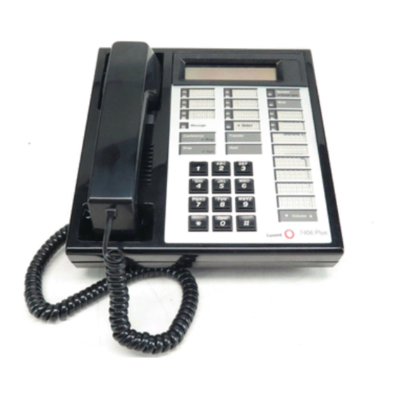
- Page 29 Figure 3-20. The 7406 Plus (7406D07A) Voice Terminal with Display …………………………… 3-146 Figure 3-21. Button Numbering for Administering the 7406D and 7406BIS Voice ………… 3-158 Terminals Connected to a System 75 or a DEFINITY G1 or G3 Switch Figure 3-22. Button Numbering for Administering the 7406D and 7406BIS Voice Terminals Connected to a System 85 or a DEFINITY G2 Switch …………………...
- Page 30 Figure 3-43. Button Numbering for Administering the 7444 Voice Terminal Connected to a System 85 or a DEFINITY G2 Switch ……………………………… 3-232 The 8403 Voice Terminal ……………………………………………………………… 3-237 Figure 3-44. Figure 3-45. Button Numbering for Administering the 8403 Voice Terminal Connected to a System 75 or a DEFINITY G1 or G3 Switch ………………………...
- Page 31 Figure 3-15. The 7505 Asynchronous Data Modular Terminal …………………………………… 3-379 Figure 3-16. The 7506 Asynchronous Data Modular Display Terminal…………………………… 3-387 Figure 3-17. The 7507 Asynchronous Data Modular Display Terminal…………………………… 3-395 Figure 3-18. The Desk-mounted ISDN 8503T Voice Terminal …………………………………… 3-403 Figure 3-19.
- Page 32 Figure 5-2. The 7400B Plus Data Module ………………………………………………………… 5-10 Figure 5-2. Block Diagram of the 7400B Interface ………………………………………………… 5-12 Figure 5-3. The 8400B Plus Data Module ………………………………………………………… 5-18 Figure 5-2. Typical Installation of the U.S. Configuration, including Telephone and Separate Power Supply ………………………………………………………………… 5-19 Figure 5-3.
- Page 33 Tables Table 2-A. Voice Terminals Usable with DEFINITY, System 75, and System 85 …………… 2-3 Table 2-B. Adjunct/Voice Terminal Compatibility ………………………………………………… 2-12 Table 2-C. Recommended Protectors ……………………………………………………………… 2-22 Table 2-D. IROB Protection ………………………………………………………………………… 2-23 Table 2-E. Availability………………………………………………………………………………… 2-26 Table 2-F. DEFINITY G1 and System 75 Voice Terminal Administration ………………………...
-
Page 35: Introduction
INTRODUCTION INTRODUCTION Purpose Voice terminals and adjuncts are voice and data devices that are connected to the system switch in a business communications system. This manual provides concise physical and functional descriptions of the voice terminals/telephones, adjuncts, and data modules that can be used with DEFINITY®... -
Page 36: Figure 1-1. Interface Between System Switch And Typical Terminals/Adjuncts
INTRODUCTION FIGURE 1-1. Interface Between System Switch and Typical Terminals/Adjuncts... -
Page 37: Organization
INTRODUCTION Organization The remainder of this manual is divided into nine main sections; tabs are provided for convenient access to each section. All equipment descriptions are supported by illustrations. GENERAL INFORMATION—Gives background data that applies to the entire range of equipment covered in this manual. - Page 38 INTRODUCTION The nine tabbed subsections and the voice terminals described in each subsection are listed as follows: 7100 SERIES CALLMASTER® Model 7101A 602 CALLMASTER Model 7102A CALLMASTER II Model 7102 Plus CALLMASTER III Model 7103A Fixed Feature Model 7103A Programmable 500/2500 SERIES Model 7104A Model 500 Series...
- Page 39 INTRODUCTION ADJUNCTS—Contains information on the devices that can be used with voice terminals to supplement services and features. This section contains information on the controls, buttons, lights, and functions of DEFINITY G1, G2, G3, System 75, and System 85 voice terminals and telephone adjuncts.
- Page 40 INTRODUCTION...
-
Page 41: General Information
GENERAL INFORMATION GENERAL INFORMATION This section provides general information on all of the equipment described in this manual. Infor- mation is provided on voice terminals, adjuncts, data modules, and data terminals. Detailed information on these types of equipment can be found behind the tab for each particular type of equipment. - Page 42 GENERAL INFORMATION Multi-Appearance Voice Terminals A multi-appearance voice terminal gives its user much more flexibility in handling calls than a single-line voice terminal. A multi-appearance voice terminal, represented by a unique primary extension number, has multiple call appearances (buttons with lights) where incoming calls to the number can be answered and outgoing calls can be originated.
-
Page 43: Table 2-A. Voice Terminals Usable With Definity, System 75, And System 85
GENERAL INFORMATION TABLE 2-A. Voice Terminals Usable with DEFINITY, System 75, and System 85 TYPE MODEL Single-Line 2500 Series Analog 2500 DMGC 2500 YMGK 2500 MMGL 2500 YMGL 7101A 7102A, 7102 Plus 7103A Fixed Feature and 7103A Programmable 7104A (usable only with DEFINITY G1 and System 75) 8101, 8102 and 8110 Multi-Appearance 7203H (usable only with DEFINITY G2 and System 85) -
Page 44: Facilities Common To All Voice Terminals
GENERAL INFORMATION Facilities Common to All Voice Terminals Every DEFINITY G1, G2, G3, System 75, and System 85 voice terminal has the following equip- ment: A pushbutton pad for touch-tone dialing (except for the Model 500, which has a rotary dial) A handset with a coiled modular cord A 7-foot modular mounting cord (except for the Model 2554 wall set). - Page 45 GENERAL INFORMATION Hold Button—is used to temporarily disconnect from one call, without dropping it, so that another call can be answered or originated. The user can return to the call on hold. Drop Button—is used to permanently disconnect the last party added to a conference call.
-
Page 46: Figure 2-1. Call Appearance/Feature Buttons
GENERAL INFORMATION Example shows button NOTE: field present.1. 7410 Plus differentarrangements, arealways have voiceterminal. terminals Other Buttons FIGURE 2-1. Call Appearance/Feature Buttons Associated with each call appearance/feature button is a pair of lights that provide information on the availability and status of the appearance. These lights are described in the next part of this manual (titled ‘‘Lights’’). -
Page 47: Figure 2-2. Button Lights
GENERAL INFORMATION Lights Indicator lights provide silent visual reminders to the voice terminal user regarding lines, features, and messages taken at other locations. The lights on DEFINITY G1, G2, G3, and System 75 and 85 voice terminals are light-emitting diodes (LEDs) or neon lights. On all multi-appearance voice terminals, each call appearance/feature button has two indicator lights: a red light and a green status light. - Page 48 GENERAL INFORMATION Red Light The red light normally has two states: lighted steadily or dark (off).* One red light is always on at a multi-appearance voice terminal when the handset is on hook. It identifies the call appearance the user will be automatically connected to if the handset is lifted. When the handset is lifted, the red light identifies the call appearance that is active.
- Page 49 GENERAL INFORMATION Tones The tones that a voice terminal user hears can be divided into two categories: Ringing Tones—those that are generated in the base of the voice terminal and can be heard in the surrounding area; they indicate incoming calls. Handset Tones—those that are transmitted through the handset and heard only by the user or through the speakerphone when it is turned on.
- Page 50 GENERAL INFORMATION Confirmation Tone—(three short bursts of tone) indicates that a feature activation or cancellation has been accepted, or that an outgoing call from a single-line voice terminal has been placed in a ringback queue. Coverage Tone—(one long burst of tone) indicates to the calling party that a call to an extension number will be answered at another extension number by a covering user.
-
Page 51: Adjuncts
GENERAL INFORMATION Adjuncts Adjuncts are optional devices that extend the existing capabilities of voice terminals or provide new services. Some adjuncts are physically attached to their voice terminals, and others are free-standing, connected by way of mounting cords. The adjuncts have styling and colors that are compatible with the associated voice terminals. -
Page 52: Table 2-B. Adjunct/Voice Terminal Compatibility
GENERAL INFORMATION TABLE 2-B. Adjunct/Voice Terminal Compatibility ADJUNCT TERMINALS FUNCTION Call Coverage Module, C201A 7205H Adds 20 call appearance/ feature buttons. Call Coverage Module, C401A 7405D 7434D Call Coverage Module, C401B 7405D 7434D Digital Display Module, D401A 7405D 7434D Displays call-related and Digital Display Module, D401B 7405D personal service information. - Page 53 GENERAL INFORMATION TABLE 2-B (continued). Adjunct/Voice Terminal Compatibility ADJUNCT TERMINALS FUNCTION Headset Adapter, 502A 7303S Provides for connection and 7305S control of standard headset. Message Waiting Indicator, Z34A 2500 Indicates that a message has been left for the terminal. Messaging Cartridge 7404D Provides display of call-related and personal...
-
Page 54: Figure 2-3. Data Link Components
GENERAL INFORMATION Data Modules Data modules provide an interface between the system’s digital switch and Data Terminal Equip- ment (DTE) or Data Communications Equipment (DCE). DTE is defined as a data source or a data link or a combination of both; typical examples are data terminals and host computers. DCE is equipment that provides the functions for establishing, maintaining, and terminating a data call;... - Page 55 GENERAL INFORMATION The following data equipment is available with DEFINITY G1, G2, G3, System 75, and System 7400A Data Module—In DTE mode, works with asynchronous DCE in the modem pool at data rates of 0.3-19.2 kbps, full-duplex. Supports both Hayes-compatible and D-lead modems.
- Page 56 GENERAL INFORMATION 2500-Series Data Service Unit (DSU), Isolating Data Interface (IDI), and Local Distri- bution Service Unit (LDSU)—DCIU interface units for DEFINITY G2 and System 85. PC Platform Products: PC/PBX Platform—PC expansion cards software XT/AT MicroChannel bus PCs in the DCP environment. Supports common, open data inter- face with PC/ISDN platform.
- Page 57 GENERAL INFORMATION Data Terminals A data terminal is a workstation at which data is entered and retrieved; it communicates through lines, trunks, switches, and data modules with data endpoints such as computers and other data terminals. Some data terminals contain built-in voice capabilities similar to digital voice terminals. For detailed information on buttons, lights, and tones, refer to the general information about voice terminals at beginning of this section.
- Page 58 GENERAL INFORMATION Call Progress Tones The following call progress tones are generated by the system: TONE FREQUENCY PATTERN (In ms) Ringback Tone 440 Hz + 480 Hz 1000 on, 3000 off; repeated Bridging Warning Tone* 440 Hz 500 on, 15000 off; repeated Busy Tone 480 Hz + 620 Hz 500 on, 500 off;...
- Page 59 GENERAL INFORMATION External Ringing Tones The following external ringing tone patterns are generated by the system: RINGING TONE PATTERN (In ms) 1200 on, 4000 off; repeated 400 on, 200 off, 600 on, 4000 off; repeated 200 on, 100 off, 200 on, 100 off, 600 on, 4000 off;...
- Page 60 GENERAL INFORMATION Indicator Lights Signals The following light signals are generated by the system for the attendant console and multi- appearance voice terminals. LAMP SIGNAL PATTERN (In ms) Dark (Off) Lighted (On) Flashing 500 on, 500 off; repeated Fluttering 50 on, 50 off; repeated Broken Flutter 5 cycles of 50 on, 50 off, followed by 500 off;...
-
Page 61: Exposed Port Protection
EXPOSED PORT PROTECTION EXPOSED PORT PROTECTION Requirements All port packs and terminals require unique protection and grounding arrangements as defined in the checklists ( AT&T System 75 Electrical Protection, Grounding, and Exposure Checklist , 555-200-120 and AT&T System 85 Electrical Protection, Grounding, and Exposure Checklist , 555-103-120). -
Page 62: Table 2-C. Recommended Protectors
EXPOSED PORT PROTECTION and 2,200 feet when using 26 AWG wire. The range can be extended to 5,000 feet (24 AWG) or 4,000 feet (24 AWG) with the use of a Data Link Protector (DLP). The DLP is an isolating transformer used to remove phantom power on the switch side and reintroduce it on the terminal side. -
Page 63: Table 2-D. Irob Protection
EXPOSED PORT PROTECTION TABLE 2-D. IROB Protection CIRCUIT REQUIRED TERMINAL PACKS PROTECTOR* NOTE SN224 7203, — 7205, SN228B, 2500 Series, SN229 2500DMGC, 7100 Series TN742, 500 Series, TN746B, 2500 Series, TN769 7100 Series SN270 7400 Series — TN754 7400 Series (ITW) TN754, V14 7400 Series... - Page 64 AVAILABILITY 2-24...
-
Page 65: Availability
AVAILABILITY AVAILABILITY This section provides the availability of the products described in this manual. The availability of these products is constantly changing as new products and different versions of existing products are introduced. The status of some of the products in this list may have changed since this manual was issued. -
Page 66: Table 2-E. Availability
AVAILABILITY TABLE 2-E. Availability EQUIPMENT ORDERING STATUS 7101A Voice Terminal 7102A01A Voice Terminal 7102A01B (7102 Plus) Voice Terminal 7103A Fixed Feature Voice Terminal 7103A Programmable Voice Terminal 7104A Voice Terminal 7203H Voice Terminal 7205H Voice Terminal 7302H Voice Terminal 7303H Voice Terminal 7303S Voice Terminal 7305H01B Voice Terminal 7305H02B Voice Terminal... - Page 67 AVAILABILITY TABLE 2-E (continued). Availability EQUIPMENT ORDERING STATUS 7410D01A Voice Terminal 7410D02A (7410 Plus) Voice Terminal 7434D Voice Terminal (packaged with display) 7434D Voice Terminal (packaged with call cov. module) 7444 Voice Terminal 8403 Voice Terminal 8410 Voice Terminal 8434 Voice Terminal CALLMASTER (602A1 and 603D1) CALLMASTER II CALLMASTER III...
- Page 68 AVAILABILITY TABLE 2-E (continued). Availability EQUIPMENT ORDERING STATUS D401A Digital Display Module D401B Digital Display Module C401A Call Coverage Module C401B Call Coverage Module C201A Call Coverage Module 4A Speakerphone S101A Speakerphone S102A Speakerphone S201A Speakerphone S202A Speakerphone S203A Speakerphone Message Cartridge 2870A1 Automatic Dialer 107 Loudspeaker...
- Page 69 AVAILABILITY TABLE 2-E (continued). Availability EQUIPMENT ORDERING STATUS DEFINITY High Speed Link Digital Terminal Data Module 7400A Data Module 7400B Data Module 7400B Plus Data Module PC/PBX Platform PC/ISDN Platform PC/PBX Connection E78 Plus/ISDN PC/ISDN Interface Software Developer’s Guide 2-29...
- Page 70 ADJUNCT POWER 2-30...
-
Page 71: Adjunct Power
ADJUNCT POWER ADJUNCT POWER Power for several of the adjuncts must be provided locally at the voice terminal or from a satellite closet through the terminal wiring. The following power supplies are currently recommended: The MSP-1 (WP92464L1) Power Supply—replaces the KS-22911 L1/2, 329A, and 353A DC power supplies and the 2012D AC transformer. - Page 72 ADJUNCT POWER 346A modular bulk DC power supply—can be used in a satellite closet only and is capa- ble of supplying power to any number of adjuncts that may be added to a digital voice terminal. This unit provides switch-selectable options for four outputs at 10 watts or two outputs at 20 watts.
-
Page 73: Information On The Older Power Supplies
ADJUNCT POWER Information on the Older Power Supplies The following diagram shows the connections with the older power supplies. Note: The MSP-1 replaces the KS-22911 L1/2, 329A, and 353A DC power supplies and the 2012D AC transformer. FIGURE 2-4. Local and Satellite Power Sources for Voice Terminals Adjuncts 2-33... - Page 74 ADJUNCT POWER One of these power supplies must be used for each voice terminal equipped with one or more adjuncts. Each of these power supplies (except the 95B1) has a maximum cable distance of 250 feet (76 m) between the power supply and the adjunct(s). The maximum cable distance for the 95B1 is 150 feet (45m).
-
Page 75: The Msp-1 Power Supply
ADJUNCT POWER The MSP-1 Power Supply The MSP-1 (WP92464L1) Power Supply can be used to supply local power to ISDN-T 65xx, 75xx, and 85xx series voice terminals connected to an AT&T DEFINITY Communications System and to the DCP 7444 and 8434 voice terminals which need auxiliary power for their vacuum fluorescent displays. - Page 76 ADJUNCT POWER Connecting the Power Supply The power output is provided through 3 modular jacks on the power supply. These jacks are labeled, from left to right, PHONE OTHER LINE -7 +8 -2 +5 The - and + numbers under ‘‘PHONE’’ and ‘‘OTHER’’ refer to the pins on which power is present and the polarity of that power.
-
Page 77: Figure 2-5. Local Powering Arrangement For: Isdn-T Vts; The Dcp 7444 And 8434 Vts
ADJUNCT POWER PHONE OTHER LINE MSP-1 -7 +8 -2 +5 Power Supply D4BU cord (for analog cord telephones) D8W cord (for DCP and ISDN-T voice terminals) Wall jack Adjunct jack Line jack Bottom view of voice terminal/telephone (7444 shown here) FIGURE 2-5. -
Page 78: Figure 2-6. Local Powering Arrangement For Adjuncts Connected To The 8102 Analog Telephone
ADJUNCT POWER PHONE OTHER LINE MSP-1 -7 +8 -2 +5 Power Supply Adjunct jack (on the rear D4BU of telephone) cord Power jack Line jack D4BU cord 2–wire cord Wall Jack Bottom view of the 8102 telephone FIGURE 2-6. Local Powering Arrangement for Adjuncts Connected to the 8102 Analog Telephone 2-38... -
Page 79: Administration
ADMINISTRATION ADMINISTRATION This section contains some of the information necessary to administer the different voice termi- nals on DEFINITY G1, G2, G3, System 75, or System 85. It also provides the caveats required when administering some of the newer voice terminals to the older systems. Other administra- tion information for DEFINITY G1 and G3 or System 75 is provided in the DEFINITY G1 and G3 and System 75 Implementation and Administration manuals. -
Page 80: Table 2-F. Definity G1 And System 75 Voice Terminal Administration
ADMINISTRATION TABLE 2-F. DEFINITY G1 and System 75 Voice Terminal Administration SYSTEM VOICE S75 R1V1 S75 R1V2 S75 R1V3 G1 and G3 TERMINAL 8101/8102/8110 2500 7102A 7101A 7101A 7104A or 2500* 7203H 7205H "MERLIN"’** 7303S SMALL "MERLIN" 7305S MEDIUM "MERLIN" 7305S LARGE 7401D... - Page 81 ADMINISTRATION TABLE 2-F (continued). DEFINITY G1 and System 75 Voice Terminal Administration X = Not Allowed DD = Digital Display Module * If equipped with a message waiting adjunct, administer as a 7101A; otherwise, administer as 2500. ** MERLIN Communications System 2-41...
- Page 82 ADMINISTRATION TABLE 2-F (continued). DEFINITY G1 and System 75 Voice Terminal Administration SYSTEM VOICE S75 R1V1 S75 R1V2 S75 R1V3 G1 and G3 TERMINAL 7405D 7405D 7434D 7444 or 7407D* or 7407D* 8403 7405** 8410B 7403 7410*** 8410D 7405+D*** DD = Digital Display Module *CAVEATS for administration of the 7444 voice terminal: If the 7444 voice terminal is administered as a 7405D or a 7407D, the following caveats apply: Only 10 call appearance buttons can be administered with two lights, a red and a green light.
- Page 83 ADMINISTRATION TABLE 2-F (continued). DEFINITY G1 and System 75 Voice Terminal Administration SYSTEM VOICE S75 R1V1 S75 R1V2 S75 R1V3 G1 and G3 TERMINAL 8434 (for 7405+D+F extra features)* 8434 (for 7434+D additional coverage)* 602 CALLMASTER CALLMASTER II & III 602 CALLMASTER 7505 ISDN 7506 ISDN...
-
Page 84: Table 2-G. Definity G1 And System 75 Terminal And Module Administration
ADMINISTRATION TABLE 2-G. DEFINITY G1 and System 75 Terminal and Module Administration SYSTEM PCs AND S75 R1V1 S75 R1V2 S75 R1V3 G1 and G3 DIGITAL MODULES 7405D PC/PBX PLATFORM DD & DM MPDM MTDM 7400A DM PDM or TDM (modem pool only) 7400B &... -
Page 85: Table 2-H. Definity G2 And System 85 Voice Terminal Administration
ADMINISTRATION TABLE 2-H. DEFINITY G2 and System 85 Voice Terminal Administration SYSTEM VOICE S85 R2V1 S85 R2V2 S85 R2V3 S85 R2V4 TERMINAL 2500 2500 YMGK 7101A 7102A 7102 Plus 7103A 7104A 10 MET 7203H 20 MET 7205H 30 MET 7205H "MERLIN"... - Page 86 ADMINISTRATION TABLE 2-H (continued). DEFINITY G2 and System 85 Voice Terminal Administration SYSTEM VOICE S85 R2V1 S85 R2V2 S85 R2V3 S85 R2V4 TERMINAL 7410D 7403D 7410 Plus 7403D 7410D 7434D 7405D 7405D DD 7434D 7444 7405D DD or 7407D* or 7407D* 8403 7405 8410B...
- Page 87 ADMINISTRATION TABLE 2-H (continued). DEFINITY G2 and System 85 Voice Terminal Administration SYSTEM VOICE S85 R2V1 S85 R2V2 S85 R2V3 S85 R2V4 TERMINAL 8434 (for 7405+D+F extra features)* 8434 (for 7434+D additional coverage)* 602 CALLMASTER CALLMASTER II & III 602 CALLMASTER 7505 ISDN 7506 ISDN 7507 ISDN...
-
Page 88: Table 2-I. Definity G2 And System 85 Terminal And Module Administration
ADMINISTRATION TABLE 2-I. DEFINITY G2 and System 85 Terminal and Module Administration SYSTEM DISPLAY TERMINALS S85 R2V1 S85 R2V2 S85 R2V3 S85 R2V4 DIGITAL MODULES 7405D PC/PBX PLATFORM PT 510D DD & DM BCT 513 EIA PORT MPDM MTDM 7400A DM PDM or TDM (modem pool only) 7400B &... -
Page 89: Button And Feature Caveats
ADMINISTRATION Button and Feature Caveats System 75 and DEFINITY G1 DO NOT SWITCH BUTTONS THAT TERMINAL ALIASED AS ASSIGN FEATURES RELEASE DO NOT EXIST* TO BUTTON(S) 7401D 7403D R1V1—R1V3 — 7406D01A— 7405D 6—10, R1V1 — 7406D04A (Note 1) 19—24 7405D 6—10, 2, 3 R1V1... - Page 90 ADMINISTRATION System 85 and DEFINITY G2 DO NOT SWITCH BUTTONS THAT TERMINAL ALIASED AS ASSIGN FEATURES RELEASE DO NOT EXIST* TO BUTTON(S) 7401D 7403D R2V1—R2V3 — 7406D01A— 7405D 8—12, R2V1—R2V3 — 7406D04A (Note 1) 31—36 7405D 8—12, 14, 15 R2V1—R2V3 7406D05A, (Note 1) 31—36...
-
Page 91: Voice Terminal Features
VOICE TERMINAL FEATURES VOICE TERMINAL FEATURES The DEFINITY G1, G2, G3, System 75 and 85 voice terminals provide a wide range of features. The following tables provide information on the major features of a particular type of telephone or voice terminal. Table A shows the features that are available with single-line voice terminals and the 7401D and 7401 Plus voice terminals. -
Page 92: Table 3-A. Single-Line (And 7401) Voice Terminal Features
VOICE TERMINAL FEATURES TABLE 3-A. Single-Line (and 7401) Voice Terminal Features VOICE TERMINALS 2500/ 2500 2500 2500 2500 PHYSICAL FEATURES 500 2554 DMGC YMGK MMGL YMGL 7101A √ √ √ √ √ √ √ Analog Digital √ √ √ √ √... - Page 93 VOICE TERMINAL FEATURES TABLE 3-A (continued). Single-Line (and 7401) Voice Terminal Features VOICE TERMINALS 7102 7103A 7103A PHYSICAL FEATURES 7102A Plus FIXED PROG. 7104A √ √ √ √ √ Analog Digital √ √ √ √ √ Touch-Tone Dial √ √ √...
- Page 94 VOICE TERMINAL FEATURES TABLE 3-A (continued). Single-Line (and 7401) Voice Terminal Features VOICE TERMINALS 7401 PHYSICAL FEATURES 7401D* Plus 8101 8102 8110 √ √ √ Analog √ √ Digital √ √ √ √ √ Touch-Tone Dial √ √ √ √ √...
-
Page 95: Table 3-B. Multi-Appearance Hybrid Voice Terminal Features
VOICE TERMINAL FEATURES TABLE 3-B. Multi-Appearance Hybrid Voice Terminal Features VOICE TERMINALS PHYSICAL FEATURES 7203H 7205H 7303S 7305S Call Appearance/ Feature Buttons with In-Use and Status Lights Feature-only Buttons √ √ √ √ Dial and Buttons Access to Features √ √... - Page 96 VOICE TERMINAL FEATURES TABLE 3-B (continued). Multi-Appearance Hybrid Voice Terminal Features VOICE TERMINALS PHYSICAL FEATURES 7203H 7205H 7303S 7305S AC Powered √ √ √ √ DC Powered Optional Enhancements √ √ √ √ Headset Adapter √ √ √ √ External Speakerphone Digital Terminal Data Module Data Module Base...
-
Page 97: Table 3-C. Multi-Appearance Digital Voice Terminal Features
VOICE TERMINAL FEATURES TABLE 3-C. Multi-Appearance Digital Voice Terminal Features VOICE TERMINALS PHYSICAL FEATURES 7402 Plus 7403D 7404D 7405D 7406D 7406BIS 7406 Plus Call Appearance/ Feature Buttons Feature-Only Buttons Shiftable Feature Buttons √ √ √ √ √ √ √ Dial and Buttons Access to Features √... - Page 98 VOICE TERMINAL FEATURES TABLE 3-C (continued). Multi-Appearance Digital Voice Terminal Features VOICE TERMINALS PHYSICAL FEATURES 7402 Plus 7403D 7404D 7405D 7406D 7406BIS 7406 Plus √ AC Powered √ √ √ √ √ √ DC Powered (supplied by PBX) Optional Enhancements √...
- Page 99 VOICE TERMINAL FEATURES TABLE 3-C (continued). Multi-Appearance Digital Voice Terminal Features VOICE TERMINALS PHYSICAL FEATURES 7407 Enhd 7407 7407 Plus 7410 7410 Plus 7434D 7444 Call Appearance/ Feature Buttons Feature-only Buttons Dual-Function Feature Buttons Display Control Buttons √ √ √ √...
- Page 100 VOICE TERMINAL FEATURES TABLE 3-C (continued). Multi-Appearance Digital Voice Terminal Features VOICE TERMINALS PHYSICAL FEATURES 7407D Enhd 7407 7407 Plus 7410 7410 Plus 7434D 7444 √ AC Powered √ √ √ √ √ √ DC Powered (supplied by PBX) Optional Enhancements √...
- Page 101 VOICE TERMINAL FEATURES TABLE 3-C (continued). Multi-Appearance Digital Voice Terminal Features VOICE TERMINALS PHYSICAL FEATURES 8403 8410 8434 602CM CM II & III Call Appearance/ Feature Buttons Feature-only Buttons √ √ √ √ √ Dial and Buttons Access to Features √...
- Page 102 VOICE TERMINAL FEATURES TABLE 3-C (continued). Multi-Appearance Digital Voice Terminal Features VOICE TERMINALS PHYSICAL FEATURES 8403 8410 8434 602 CM CM II & III AC Powered √ √ √ √ √ DC Powered (supplied by PBX) (Note 6) Optional Enhancements √...
-
Page 103: Table 3-D. Multi-Appearance Isdn Voice Terminal Features
VOICE TERMINAL FEATURES TABLE 3-D. Multi-Appearance ISDN Voice Terminal Features VOICE TERMINALS PHYSICAL FEATURES 7505 7506 7507 8503T 8510T 8520T Call Appearance/ Feature Buttons with Lights (Note 7) (Note 7) (Note 7) Shiftable Feature Buttons Feature-Only Buttons √ √ √ √... - Page 104 VOICE TERMINAL FEATURES 3-14...
-
Page 105: 7101A Voice Terminal
VOICE TERMINAL FEATURES 7101A VOICE TERMINAL MESSAGE LIGHT FIGURE 3-1. The 7101A Voice Terminal 3-15... - Page 106 VOICE TERMINAL FEATURES 3-16...
-
Page 107: Applications
7101A Voice Terminal 7101A Voice Terminal The 7101A voice terminal is a single-line analog model that requires one tip and ring pair for operation. It is equipped with a Message Waiting light and a handy Recall button for activating the system’s special features. It cannot be physically bridged to the same analog line port due to the message waiting and loop current circuitry. - Page 108 7101A Voice Terminal Message Light The green Message light goes on when a message is left for the user. It goes off when the user retrieves the message. Other Physical Features Handset The 7101A is equipped with an R-type handset. Dial pad The 7101A is equipped with a 12-button touch-tone dial pad.
-
Page 109: Distance Limitations
7101A Voice Terminal Distance Limitations The maximum allowable distances of a 7101A from the DEFINITY G1, G2, G3, System 75, or System 85 cabinet are shown in the table below. NOMINAL MAXIMUM RANGE IN FEET (METERS) SYSTEM PORT BOARD SEE NOTE 24 AWG 26 AWG SYSTEM 85... -
Page 110: Hearing Aid Compatible
7101A Voice Terminal Hearing Aid Compatible This voice terminal is compatible with the inductively coupled hearing aids prescribed by the FCC. 3-20... -
Page 111: 7101A Equipment Price Element Code (Pecs)
7101A Voice Terminal 7101A Equipment Price Element Code (PECs) The 7101A Voice Terminal and optional components can be ordered with the following PECs: Basic voice terminal (black)—3170-00M Handset cord (12 feet, black)—2725-01L COL09 Line cord (14 feet, silver)—2725-07N COL18 Line cord (25 feet, silver)—2725-07S COL18 Adjuncts None. - Page 112 7101A Voice Terminal 3-22...
-
Page 113: 7102A And 7102 Plus Voice Terminals
7101A Voice Terminal 7102A and 7102 Plus VOICE TERMINALS FIGURE 3-2. The 7102A and 7102 Plus Voice Terminal 3-23... - Page 114 7101A Voice Terminal 3-24...
-
Page 115: Applications
7102A and 7102 Plus Voice Terminals 7102A and 7102 Plus Voice Terminals The 7102A voice terminal is available in two versions, the 7102A01A and the 710201B, called the 7102 Plus. The front of the two sets is exactly the same in appearance. The only difference is that the 7102A01B is equipped with an adjunct jack. - Page 116 7102A and 7102 Plus Voice Terminals Features One Fixed Feature Button The RECALL Button Message Light The red Message light flashes when a message is left for the user. It goes off when the user retrieves the message. Other Physical Features Handset The 7102 voice terminals are equipped with an R-type handset.
- Page 117 7102A and 7102 Plus Voice Terminals Mounting Options The 7102 voice terminals come equipped with both a non-adjustable desk stand and a wall mounting bracket. Color Options The 7102 voice terminals are available in two colors: black and misty cream. 3-27...
-
Page 118: Distance Limitations
7102A and 7102 Plus Voice Terminals Distance Limitations The maximum allowable distances of a 7102A or 7102 Plus voice terminal from the DEFINITY G1, G2, G3, System 75, or System 85 cabinet are shown in the table below. NOMINAL MAXIMUM RANGE IN FEET (METERS) SYSTEM PORT BOARD... -
Page 119: Fcc Registration
7102A and 7102 Plus Voice Terminals FCC Registration The 7102 voice terminals are FCC registered (AS-593M-17706-TE-T). Hearing Aid Compatible This voice terminal is compatible with the inductively coupled hearing aids prescribed by the FCC. 7102 Equipment Price Element Code (PECs) The 7102A and the 7102 Plus voice terminals and optional components can be ordered with the following PECs: 7102A voice terminal (black and misty cream)—3185-MWR (not orderable) - Page 120 7102A and 7102 Plus Voice Terminals DEFINITY Generic 2 and System 85 7102 Voice Terminal User’s Guide , 555-104-715 DEFINITY Generic 1 and Generic 2, System 75, and System 85 Terminals and Adjuncts Installation and Test , 555-015-104 3-30...
-
Page 121: 7103A Fixed Feature Voice Terminal
7102A and 7102 Plus Voice Terminals 7103A FIXED FEATURE VOICE TERMINAL MESSAGE LIGHT FIGURE 3-3. The 7103A Fixed Feature Voice Terminal 3-31... - Page 122 7102A and 7102 Plus Voice Terminals 3-32...
-
Page 123: Applications
7102A and 7102 Plus Voice Terminals 7103A Fixed Feature Voice Terminal The 7103A Fixed Feature voice terminal is a single-line analog model which has been discontin- ued. The feature buttons on this terminal must be programmed by the system manager. It requires one tip and ring pair for operation. - Page 124 7103A Fixed Feature Voice Terminal Eight Feature Buttons The System Manager designates and programs all buttons, except fixed feature buttons, for the common needs of all voice terminal users. Within any one system, all 7103A Fixed Feature voice terminals have identical features at the same button positions. Message Light The green Message light goes on when a message is left for the user.
-
Page 125: Distance Limitations
7103A Fixed Feature Voice Terminal Color Options The 7103A voice terminal is available in black only. Distance Limitations The maximum allowable distances of a 7103A voice terminal from the DEFINITY G1, G2, G3, System 75, or System 85 cabinet are shown in the table below. NOMINAL MAXIMUM RANGE IN FEET (METERS) SYSTEM... -
Page 126: Fcc Registration
7103A Fixed Feature Voice Terminal FCC Registration The 7103A voice terminal is not FCC registered. Hearing Aid Compatible This voice terminal is compatible with the inductively coupled hearing aids prescribed by the FCC. 3-36... -
Page 127: 7103A (Fixed Feature) Equipment Price Element Code (Pecs)
7103A Fixed Feature Voice Terminal 7103A (Fixed Feature) Equipment Price Element Code (PECs) The 7103A voice terminal and optional components was ordered with the following PECs: Basic voice terminal—(not orderable) Handset cord (12 feet, black)—2725-01L COL09 Line cord (14 feet, silver)—2725-07N COL18 Line cord (25 feet, silver)—2725-07S COL18 Adjuncts One of the following adjuncts can be used with this voice terminal:... - Page 128 7103A Fixed Feature Voice Terminal 3-38...
-
Page 129: 7103A Programmable Voice Terminal
7103A Fixed Feature Voice Terminal 7103A PROGRAMMABLE VOICE TERMINAL MESSAGE LIGHT FIGURE 3-4. The 7103A Programmable Voice Terminal 3-39... - Page 130 7103A Fixed Feature Voice Terminal 3-40...
-
Page 131: Applications
7103A Programmable Voice Terminal 7103A Programmable Voice Terminal The 7103 Programmable voice terminal is a single-line analog model no longer manufactured. However, some remanufactured terminals may still be ordered. The 10 feature buttons can be programmed by the user for one-touch feature access or for one-touch Speed Dialing. It requires one tip and ring pair for operation. - Page 132 7103A Programmable Voice Terminal PROGRAM button —This button is used to enter mode for programming feature buttons for feature access or for Repertory Dialing. With the Repertory Dialing feature, the termi- nal user can store in-house or external numbers. Operation of this button also puts the Last Number/Wait button into the Wait mode.
-
Page 133: Distance Limitations
7103A Programmable Voice Terminal Mounting Options The 7103A voice terminal comes equipped with a nonadjustable desk stand. An adjustable desk stand or a wall mounting bracket can be optionally ordered. Color Options The 7103A voice terminal is available in black only. Distance Limitations The maximum allowable distances of a 7103A voice terminal from the DEFINITY G1, G2, G3, System 75, or System 85 cabinet are shown in the table below. -
Page 134: Power Failure Operation
7103A Programmable Voice Terminal Power Failure Operation The 7103A voice terminal cannot be used as an emergency station during power failure transfer conditions. FCC Registration The 7103A voice terminal is not FCC registered. 3-44... -
Page 135: Hearing Aid Compatible
7103A Programmable Voice Terminal Hearing Aid Compatible This voice terminal is compatible with the inductively coupled hearing aids prescribed by the FCC. 7103A (Programmable) Equipment Price Element Code (PECs) The 7103A voice terminal and optional components can be ordered with the following PECs: Basic voice terminal—3171-14F Handset cord (12 feet, black)—2725-01L COL09 Line cord (14 feet, silver)—2725-07N COL18... - Page 136 7103A Programmable Voice Terminal 3-46...
-
Page 137: 7104A Voice Terminal
7103A Programmable Voice Terminal 7104A VOICE TERMINAL Figure 1. The 7104A Voice Terminal 3-47... - Page 138 7103A Programmable Voice Terminal Figure 2. The 7104A Voice Terminal with attached Message Waiting Adjunct 3-48...
-
Page 139: Applications
7103A Programmable Voice Terminal 7104A Voice Terminal The 7104A voice terminal is a single-line analog model no longer manufactured. However, some remanufactured terminals may still be ordered. The 7104A voice terminal is equipped with a display that is used to display stored numbers. It requires one tip and ring pair for operation. It cannot be physically bridged to the same analog line port due to the message waiting and loop current circuitry. - Page 140 7104A Voice Terminal Eight Special Fixed Feature Buttons SHIFT button —used for toggling between the two modes of the following four dual func- tion feature buttons and the eight dual function one-touch dialing buttons. SET CLOCK/TIMER button —used for setting time and for timing a call. AM/DLYD RING button —used in time-setting procedure and to delay ringing on incom- ing calls.
- Page 141 7104A Voice Terminal Pull out tray The 7104A voice terminal is equipped with a pull out tray with an Instruction card for Voice Termi- nal operation. Other Physical Features Handset The 7104A voice terminal is equipped with an R-type handset. Dial pad The 7104A voice terminal is equipped with a 12-button touch-tone dial pad.
-
Page 142: Distance Limitations
7104A Voice Terminal Distance Limitations The maximum allowable distances of a 7104A voice terminal from the DEFINITY G1, G3 and System 75 cabinet are shown in the table below. NOMINAL MAXIMUM RANGE IN FEET (METERS) SYSTEM PORT BOARD 24 AWG 26 AWG DEFINITY G1 &... -
Page 143: 7104 Equipment Price Element Code (Pecs)
7104A Voice Terminal 7104 Equipment Price Element Code (PECs) The 7104A voice terminal and optional components can be ordered with the following PECs: Basic voice terminal (black, misty cream, and chocolate brown)—3150-010 Handset cord (12 feet, black)—2725-01L COL09 Line cord (14 feet, silver)—2725-07N COL18 Line cord (25 feet, silver)—2725-07S COL18 Adjuncts The optional Z34A Message waiting Adjunct can be used with this voice terminal to provide a... - Page 144 7104A Voice Terminal 3-54...
-
Page 145: 7203H Voice Terminal
7104A Voice Terminal 7203H VOICE TERMINAL MESSAGE LIGHT FIGURE 3-5. The 7203H Voice Terminal 3-55... - Page 146 7104A Voice Terminal 3-56...
-
Page 147: Applications
7203H Voice Terminal 7203H Voice Terminal The 7203H voice terminal is a multi-appearance hybrid voice terminal which provides for up to 10 incoming lines. Buttons not used for line appearances may be used for one-touch feature access or for Speed Dialing. It requires three pair wiring for operation. One wire pair is used for analog voice, while the other two pairs are used for digital control and signaling. - Page 148 7203H Voice Terminal CONFERENCE button DROP button TRANSFER button HOLD button Message Light The green Message light goes on when a message is left for the user. It goes off when the user retrieves the message. Call Appearance/Feature Buttons The 7203H voice terminal has 10 call appearance/feature buttons. Adjacent to each button is a pair of red and green status indicator lights.
-
Page 149: Distance Limitations
7203H Voice Terminal Ringing The 7203H voice terminal has electronic tone ringing. The volume control is on the left side of the housing. Mounting Options The 7203H voice terminal comes equipped with a nonadjustable desk stand. An optional wall mounting kit can be ordered. Color Options The 7203H voice terminal was available in various colors;... -
Page 150: Fcc Registration
7203H Voice Terminal FCC Registration The 7203H voice terminal is not FCC registered. Hearing Aid Compatible This voice terminal is compatible with the inductively coupled hearing aids prescribed by the FCC. 3-60... -
Page 151: 7203H Equipment Price Element Code (Pecs)
7203H Voice Terminal 7203H Equipment Price Element Code (PECs) The 7203H voice terminal and optional components were ordered with the following PECs: Basic voice terminal—3182-16H/CLR Handset cord (12 feet)—2725-01L COL09 Line cord (14 feet, silver)—2725-07N COL18 Line cord (25 feet, silver)—2725-07S COL18 Adjuncts One of the following adjuncts can be used with this voice terminal: S101A Speakerphone... - Page 152 7203H Voice Terminal 3-62...
-
Page 153: 7205H Voice Terminal
7203H Voice Terminal 7205H VOICE TERMINAL MESSAGE LIGHT FIGURE 3-6. 7205H Voice Terminal 3-63... - Page 154 7203H Voice Terminal 3-64...
-
Page 155: Applications
7205H Voice Terminal 7205H Voice Terminal The 7205H is a multi-appearance hybrid voice terminal which provides six buttons for fixed features, 10 buttons for line appearances or one-touch feature activation, and 24 feature-only buttons. It requires 3-pair wiring for operation. One wire pair is used for analog voice, while the other two pairs are used for digital control and signaling. - Page 156 7205H Voice Terminal CONFERENCE button DROP button TRANSFER button HOLD button Message Light The green Message light goes on when a message is left for the user. It goes off when the user retrieves the message. Call Appearance/Feature Buttons The 7205H voice terminal has 10 call appearance/feature buttons. Adjacent to each button is a pair of red and green indicator lights.
-
Page 157: Distance Limitations
7205H Voice Terminal Ringing The 7205H voice terminal has electronic tone ringing. The volume control is on the left side of the housing. Mounting Options The 7205H voice terminal comes equipped with a nonadjustable desk stand. An optional wall mounting kit can be ordered. Color Options The 7205H voice terminal was available in various colors;... -
Page 158: Power Failure Operation
7205H Voice Terminal Power Failure Operation The 7205H voice terminal cannot be used as an emergency station during power failure transfer conditions. FCC Registration The 7205H voice terminal is not FCC registered. Hearing Aid Compatible This voice terminal is compatible with the inductively coupled hearing aids prescribed by the FCC. 7205H Equipment Price Element Code (PECs) The 7205H voice terminal and optional components was ordered with the following PECs: Basic voice terminal—3183-40H/CLR... -
Page 159: Additional Documents
7205H Voice Terminal Additional Documents The following documents contain additional information relating to the 7205H voice terminal: System 85 7205H Voice Terminal User’s Guide , 555-102-709 DEFINITY Generic 1 and Generic 2, System 75, and System 85 Terminals and Adjuncts Installation and Test , 555-015-104 3-69... - Page 160 7205H Voice Terminal 3-70...
-
Page 161: 7303S Voice Terminal
7205H Voice Terminal 7303S VOICE TERMINAL MESSAGE SPEAKER LIGHT LIGHT FIGURE 3-7. The 7303S Voice Terminal 3-71... - Page 162 7205H Voice Terminal 3-72...
-
Page 163: Applications
7303S Voice Terminal 7303S Voice Terminal The 7303S is a multi-appearance hybrid voice terminal which provides access to 10 line appear- ances or selected programmable features. The 7303S voice terminal is also equipped with six fixed feature buttons. It requires 3-pair wiring for operation. One wire pair is used for analog voice, while the other two pairs are used for digital control and signaling. - Page 164 7303S Voice Terminal DROP button TRANSFER button HOLD button Message Light The green Message light goes on when a message is left for the user. It goes off when the user retrieves the message. Call Appearance/Feature Buttons The 7303S voice terminal has 10 call appearance/feature buttons. Adjacent to each button is a pair of red and green indicator lights.
-
Page 165: Distance Limitations
7303S Voice Terminal Cords Two cords are supplied with the 7303S voice terminal: a coiled 7-foot modular handset cord and a 7-foot modular line cord. Optional longer cords are available: a 12-foot handset cord; 14-foot and 25-foot line cords. Ringing The 7303S voice terminal has electronic tone ringing. -
Page 166: Power Requirements
7303S Voice Terminal Note: Range may be extended to 2,000 feet (610m) for 24- or 26-AWG wire by adding local -48 volt DC power in the satellite closet. Power supplies such as the 346A or 329A may be connected to the fourth pair from the terminals to obtain the increased range. -
Page 167: Adjuncts
7303S Voice Terminal Adjuncts One of the following adjuncts can be used with this voice terminal: S102A Speakerphone S202A Speakerphone 502A Headset Adapter and a standard headset Additional Documents The following documents contain additional information relating to the 7303S voice terminal: DEFINITY Generic 2, System 85 7303S Voice Terminal User’s Guide , 555-103-707 DEFINITY Generic 1, System 75 7303S Voice Terminal User’s Guide , 555-200-706 DEFINITY Generic 1 and Generic 2, System 75, and System 85 Terminals and Adjuncts... - Page 168 7303S Voice Terminal 3-78...
-
Page 169: 7305S Voice Terminal
7303S Voice Terminal 7305S VOICE TERMINAL MESSAGE SPEAKER LIGHT LIGHT FIGURE 3-8. The 7305S Voice Terminal 3-79... - Page 170 7303S Voice Terminal 3-80...
-
Page 171: Applications
7305S Voice Terminal 7305S Voice Terminal The 7305S voice terminal is a multi-appearance hybrid voice terminal which provides access to 10 line appearances. The 10 line appearance buttons can also be used as programmable feature buttons. The 7305S voice terminal is also equipped with 24 programmable feature buttons and six fixed feature buttons. - Page 172 7305S Voice Terminal HOLD button Message Light The green Message light goes on when a message is left for the user. It goes off when the user retrieves the message. Call Appearance/Feature Buttons The 7305S voice terminal has 10 call appearance/feature buttons. Adjacent to each button is pair of red and green indicator lights.
-
Page 173: Distance Limitations
7305S Voice Terminal the bottom center of the housing. The modular speakerphone/handset jack is located on the bot- tom of the set. Cords Two cords are supplied with the 7305S voice terminal: a coiled 7-foot modular handset cord and a 7-foot modular line cord. Optional longer cords are available: a 12-foot handset cord; 14-foot and 25-foot line cords. -
Page 174: Power Requirements
7305S Voice Terminal NOMINAL MAXIMUM RANGE IN FEET (METERS) (See NOTE) SYSTEM PORT BOARD ADJUNCTS 24 AWG 26 AWG SYSTEM 85 ANN17B 1,000 (305) 650 (198) 700 (213) 450 (137) DEFINITY G2 ANN17B 1,000 (305) 650 (198) 700 (213) 450 (137) TN762B 1,000 (305) 750 (229) -
Page 175: Hearing Aid Compatible
7305S Voice Terminal Hearing Aid Compatible This voice terminal is compatible with the inductively coupled hearing aids prescribed by the FCC. 7305S Equipment Price Element Code (PECs) The 7305S voice terminal and optional components were ordered with the following PECs: Basic voice terminal (black)—3177-40SA/CLR Handset cord (12 feet)—2725-01L COL09 Line cord (14 feet, silver)—2725-07N COL18... -
Page 176: Additional Documents
7305S Voice Terminal Additional Documents The following documents contain additional information relating to the 7305S voice terminal: System 85 7305S Voice Terminal User’s Guide , 555-103-707 System 75 7305S Voice Terminal User’s Guide , 555-200-706 DEFINITY Generic 1 and Generic 2, System 75, and System 85 Terminals and Adjuncts Installation and Test , 555-015-104 3-86... - Page 177 7305S Voice Terminal 3-87...
-
Page 178: Figure 3-9. The 7401 Plus (7401D02A) Voice Terminal
7305S Voice Terminal 7401D and 7401 Plus VOICE TERMINAL SPEAKERPHONE/HEADSET RINGER VOLUME CONTROL ADAPTER JACK (ON THE 7401D, CONTROL IS ON LEFT SIDE; (ON BACK OF VOICE TERMINAL ON THE 7401 PLUS, CONTROL IS ON BACK OF VOICE TERMINAL) FOR 7401 PLUS ONL Y) FEATURE DIRECTORY HANDSET... - Page 179 7305S Voice Terminal 3-89...
- Page 180 7305S Voice Terminal 3-90...
-
Page 181: 7401D And 7401 Plus Voice Terminals
7401D and 7401 Plus Voice Terminals 7401D and 7401 Plus Voice Terminals The 7401D (7401D01A) and the 7401 Plus (7401D02A, the newest 7401 set) are both single appearance digital voice terminals which have no call appearance buttons or lights, but have two virtual call appearances (refer to the section below titled Special Operational Characteristics). -
Page 182: Physical Features
7401D and 7401 Plus Voice Terminals 1. If either of the status lights of the virtual call appearances is flashing when the user takes the telephone off-hook, the voice terminal will always pick-up the ‘‘ringing’’ call. If both virtual call appearances are in the flashing state, the voice terminal will select the call that was ringing for the longer period of time. - Page 183 7401D and 7401 Plus Voice Terminals Seven administrable feature buttons used with the FEATURE button Feature/Call Activity Light The green Feature/Call Activity light goes on steadily when the user presses the FEATURE but- ton. This light flutters when there is an incoming call, when a call is put on hold, or when a call has been answered by another bridged extension.
-
Page 184: Distance Limitations
7401D and 7401 Plus Voice Terminals The 7401 Plus (7401D02A) voice terminal also has a Speakerphone/headset adapter jack to which the user can connect adjunct equipment. Cords Two cords are supplied with the 7401D (7401D01A) and the 7401 Plus (7401D02A) voice termi- nal: a coiled 9-foot handset cord and a 7-foot line cord. -
Page 185: Power Requirements
7401D and 7401 Plus Voice Terminals NOMINAL MAXIMUM RANGE IN FEET (METERS) (SEE NOTE) SYSTEM PORT BOARD 24 AWG 26 AWG System 85 SN270B 3,400 (1,034) 2,200 (671) TN754 3,400 (1,034) 2,200 (671) DEFINITY G2 SN270B 3,400 (1,034) 2,200 (671) TN754 3,400 (1,034) 2,200 (671) -
Page 186: Switch Administration
7401D and 7401 Plus Voice Terminals Switch Administration Aliasing The 7401 voice terminals must be aliased in the following way: If this type of Is connected to It must be voice terminal: this system: administered as: 7401D System 75, R1V1, V2, V3 a 7403D voice terminal 7401 Plus System 85, R2V1, V2, V3... - Page 187 7401D and 7401 Plus Voice Terminals Note: Although these figures show the 7401 Plus set, the administration of the two types of voice terminals is the same. If you need more information, refer to DEFINITY Communications System Generic 3 Implemen- tation , and DEFINITY Communications System Generic 2 Administration of Features and Hardware .
-
Page 188: Figure 3-10. Button Numbering For Administering The 7401D And 7401 Plus Voice Terminals Connected To A System 75 Or A Definity G1 Or G3 Switch
7401D and 7401 Plus Voice Terminals Feature Directory Buttons 1 and 2 are line appearances. Buttons 3 – 9 are F1 – F7. F8 Conference F9 Transfer F0 Drop F# Hold F* Select Ring PQRS WXYZ Oper Message Feature FIGURE 3-10. Button Numbering for Administering the 7401D and 7401 Plus Voice Terminals Connected to a System 75 or a DEFINITY G1 or G3 Switch 3-98... -
Page 189: Figure 3-11. Button Numbering For Administering The 7401D And 7401 Plus Voice Terminals Connected To A System 85 Or A Definity G2 Switch
7401D and 7401 Plus Voice Terminals Feature Directory Buttons 1 and 2 are the Hold button and the Message light. Buttons 3 and 4 are line appearances. Buttons 5 – 11 are F1 through F7. F8 Conference F9 Transfer F0 Drop F# Hold F* Select Ring PQRS... -
Page 190: Power Failure Operation
7401D and 7401 Plus Voice Terminals Power Failure Operation The 7401D and 7401 Plus voice terminals cannot be used as an emergency station during power failure transfer conditions. FCC Registration These voice terminals are FCC-registered along with the switch (as a system), but do not have a separate FCC registration label. -
Page 191: 7401 Plus Equipment With Pecs And Comcodes
7401D and 7401 Plus Voice Terminals Line cord (14 feet, silver) PEC: 2725-07N (COL18) COMCODE: 103786802 Line cord (25 feet, silver) PEC: 2725-07S (COL18) COMCODE: 103786828 Faceplate and tab COMCODE: Black=846209161; Misty Cream=846209179 Button designation cards (Package of 50) PEC: 31841 (Black=COL09; Misty Cream=COL22) COMCODE: Black=846051225;... - Page 192 7401D and 7401 Plus Voice Terminals Faceplate (Package of 50) PEC: 31846 COMCODE: Black=846551141 Misty Cream=846551406 Button designation card PEC: 31844 (Package of 50 cards) Single Sheets, COMCODE: 846521656 Pack of 50, COMCODE: 846521664 Tractor Feed, 200 Sheets, COMCODE: 846551672 Tractor Feed, 500 Sheets, COMCODE: 846551680.
-
Page 193: Adjuncts
7401D and 7401 Plus Voice Terminals Adjuncts One of the following adjuncts can be used with the 7401D (7401D01A) voice terminal: R6 Amplifier Handset (PEC: 3152-002) R8 Noisy Location Handset (PEC: 3152-003) 7400B Data Module The following adjuncts can be used with the 7401 Plus (7401D02A) voice terminal: S101A Speakerphone (no longer orderable) S201A Speakerphone... -
Page 194: Additional Documents
7401D and 7401 Plus Voice Terminals Additional Documents The following documents contain additional information relating to the 7401D and 7401 Plus voice terminals: (Use the 9 digit number listed after each document to order the book from the GBCS Publications Fulfillment Center.) 7401D Voice Terminal Installation Instructions , 555-015-106 System 75 7401D Voice Terminal User’s Guide , 555-200-727 DEFINITY Communications System Generic 1 7401D Voice Terminal User’s Guide ,... -
Page 195: 7402 Plus Voice Terminal
7401D and 7401 Plus Voice Terminals 7402 Plus VOICE TERMINAL MESSAGE 2 CALL APPEARANCE/ LIGHT FEATURE BUTTONS AND 4 FEATURE-ONLY BUTTONS CONFERENCE/ RING BUTTON DROP/TEST BUTTON SPEAKERPHONE/HEADSET ADAPTER JACK (ON BACK OF VOICE TERMINAL) SELECT BUTTON TRANSFER BUTTON SPEAKER BUTTON HOLD BUTTON VOLUME CONTROL... - Page 196 7401D and 7401 Plus Voice Terminals 3-106...
-
Page 197: Applications
7401D and 7401 Plus Voice Terminals 7402 Plus Voice Terminal The 7402 Plus is a multi-appearance digital voice terminal with two line appearances, four vari- able feature buttons, four standard fixed feature buttons (CONFERENCE, DROP, TRANSFER, and HOLD), a SELECT button, a Message light, a SPEAKER button for accessing a listen-only speaker, a Ringer Volume control, and a Speakerphone/headset adapter jack on the back of the voice terminal for connecting adjunct equipment. - Page 198 7402 Plus Voice Terminal Features Four Standard Fixed Feature Buttons CONFERENCE/RING button DROP/TEST button TRANSFER button HOLD button Message Light The red Message light goes on when a message is left for the user. It goes off when the user retrieves the message.
- Page 199 7402 Plus Voice Terminal VOLUME control button When the speaker is active on the 7402 Plus voice terminal speaker, the VOLUME control button affects the loudness of the Speaker (listen-only) feature. At all other times (when the speaker is not being used), the VOLUME control button affects the volume of the tone ringer.
- Page 200 7402 Plus Voice Terminal Ringing The 7402 Plus voice terminal has electronic tone ringing. With the Personalized Ringing feature, the user can choose any one of eight different ringing patterns. The volume on the 7402 Plus voice terminal can be controlled with the VOLUME ‘‘arrow’’ button on the front of the voice terminal.
-
Page 201: Distance Limitations
7402 Plus Voice Terminal Distance Limitations The maximum allowable distances of a 7402 Plus voice terminal from the DEFINITY G1, G2, G3, System 75, or System 85 cabinet are shown in the following table. NOMINAL MAXIMUM RANGE IN FEET (METERS) (SEE NOTE) SYSTEM PORT BOARD 24 AWG... -
Page 202: Switch Administration
7402 Plus Voice Terminal Switch Administration Aliasing The 7402 voice terminals must be aliased in the following way: If you are administering the The voice terminal must 7402 Plus with this system: be administered as a: System 75, R1V1, V2 7403D voice terminal System 75, R1V3 7410D... -
Page 203: Figure 3-13. Button Numbering For Administering The 7402 Plus Voice Terminal
7402 Plus Voice Terminal Select Message Conference Transfer Ring Drop Hold Test PQRS WXYZ Oper Volume Speaker FIGURE 3-13. Button Numbering for Administering the 7402 Plus Voice Terminal Connected to a System 75 or a DEFINITY G1 or G3 Switch 3-113... -
Page 204: Figure 3-14. Button Numbering For Administering The 7402 Plus Voice Terminal
7402 Plus Voice Terminal Select Message Conference Transfer Ring Drop Hold Test PQRS WXYZ Oper Volume Speaker NOTE: THE HOLD BUTTON IS BUTTON #1. THE MESSAGE LIGHT IS BUTTON #2. FIGURE 3-14. Button Numbering for Administering the 7402 Plus Voice Terminal Connected to a System 85 or a DEFINITY G2 Switch 3-114... -
Page 205: Power Failure Operation
7402 Plus Voice Terminal Power Failure Operation The 7402 Plus voice terminal cannot be used as an emergency station during power failure transfer conditions. FCC Registration The 7402 Plus voice terminal is FCC-registered along with the switch (as a system), but does not have a separate FCC registration label. -
Page 206: Adjuncts
7402 Plus Voice Terminal Line cord (14 feet, silver) PEC: 2725-07N (COL18) COMCODE: 103786802 Line cord (25 feet, silver) PEC: 2725-07S (COL18) COMCODE: 103786828 Button designation card PEC: 31866A (Package of 25 tractor feed cards) PEC: 31890A (Package of 100 tractor feed cards) Single sheets COMCODE: 846523892 Pack of 50 COMCODE: 846523900 Tractor feed, 200 Sheets COMCODE: 846551448... -
Page 207: Additional Documents
7402 Plus Voice Terminal Headsets A list of compatible headsets, consisting of both modular and plug prong base units and selection of headpieces, appears in ‘‘Headset Adapters’’ in the Adjuncts section (behind the Adjuncts tab) later in this manual. Additional Documents The following documents contain additional information relating to the 7402 Plus voice terminal: (use the 9-digit number listed after each document to order the book from the GBCS Publications Fulfillment Center.) - Page 208 7402 Plus Voice Terminal 3-118...
-
Page 209: 7403D Voice Terminal
7402 Plus Voice Terminal 7403D VOICE TERMINAL MESSAGE LIGHT FIGURE 3-15. The 7403D Voice Terminal 3-119... - Page 210 7402 Plus Voice Terminal 3-120...
-
Page 211: Applications
7402 Plus Voice Terminal 7403D Voice Terminal The 7403D is a multi-appearance digital voice terminal which has 10 buttons available for line appearances, one-touch feature access, or Speed Dialing. In addition, the 7403D voice terminal may be equipped with a Digital Terminal Data Module (DTDM) which attaches to the right side and allows the connection of a EIA RS-232C data terminal. - Page 212 7403D Voice Terminal DROP button TRANSFER button HOLD button Message light The green Message light goes on when a message is left for the user. It goes off when the user retrieves the message. Call Appearance/Feature Buttons The 7403D voice terminal has 10 call appearance/feature buttons. Adjacent to each button is a red light and a green status indicator light.
-
Page 213: Distance Limitations
7403D Voice Terminal Ringing The 7403D voice terminal has electronic tone ringing. The volume control is on the left side of the housing. Mounting Options The 7403D voice terminal comes equipped with a nonadjustable desk stand. An optional wall mounting kit can be ordered. Color Options The 7403D voice terminal was available in black and misty cream. -
Page 214: Power Failure Operation
7403D Voice Terminal Power Failure Operation The 7403D voice terminal cannot be used as an emergency station during power failure transfer conditions. FCC Registration The 7403D voice terminal is not FCC registered. 3-124... -
Page 215: Hearing Aid Compatible
7403D Voice Terminal Hearing Aid Compatible This voice terminal is compatible with the inductively coupled hearing aids prescribed by the FCC. 7403D Equipment Price Element Code (PECs) The 7403D voice terminal has been discontinued, and thus it cannot be ordered. Adjuncts One of the following adjuncts can be used with this voice terminal: S101A Speakerphone... - Page 216 7403D Voice Terminal 3-126...
-
Page 217: 7404D Voice Terminal
7403D Voice Terminal 7404D VOICE TERMINAL MESSAGE LIGHT PROGRESSLIGHT TA CALLIN FIGURE 3-16. The 7404D Voice Terminal 3-127... - Page 218 7403D Voice Terminal 3-128...
-
Page 219: Applications
7404D Voice Terminal 7404D Voice Terminal The 7404D is a multi-appearance digital voice terminal which provides simultaneous voice/asynchronous data transmission. All the transmission is done over the same two pairs of wire. The 7404D voice terminal can be equipped with one of two different optional cartridges. The Z300B cartridge provides a display of voice call related and personal service information on an attached data terminal. - Page 220 7404D Voice Terminal TRANSFER button HOLD button Message Light The green Message light goes on when a message is left for the user. It goes off when the user retrieves the message. Data Light The Data light goes on when a data call is in progress. Call Appearance/Feature Buttons The 7404D voice terminal has six call appearance/feature buttons.
-
Page 221: Distance Limitations
7404D Voice Terminal Cords Three cords are supplied with the 7404D voice terminal: a coiled 7-foot modular handset cord, 7- foot modular line cord and an AC power cord. Optional longer cords are available: a 12-foot handset cord; 14-foot and 25-foot line cords. Ringing The 7404D voice terminal has electronic tone ringing with patterns that are set at administration. -
Page 222: Power Requirements
7404D Voice Terminal Power Requirements The 7404D voice terminal requires a three prong 115-volt AC outlet not under the control of a wall switch for power. A built in power supply converts the 115 volts to the DC power required. A 3- wire AC power cord is provided with the voice terminal. -
Page 223: Adjuncts
7404D Voice Terminal Adjuncts The 7404D voice terminal cannot be equipped with an external adjunct. The data base contains a slot where optional cartridges can be installed to provide different features. These cartridges are identified in the introduction paragraph of this section. Additional Documents The following documents contain additional information relating to the 7404D voice terminal: System 85 7404D Voice Terminal User’s Guide , 555-103-708... - Page 224 7404D Voice Terminal 3-134...
-
Page 225: 7405D Voice Terminal
7404D Voice Terminal 7405D VOICE TERMINAL MESSAGE LIGHT FIGURE 3-17. The 7405D Voice Terminal 3-135... - Page 226 7404D Voice Terminal 3-136...
-
Page 227: Applications
7405D Voice Terminal 7405D Voice Terminal The 7405D voice terminal is a multi-appearance digital voice terminal which allows features to be added as the user needs them. The Digital Display can be added to provide access to the Mes- sage Center. A Digital Terminal Data Module or 7400B can be added to enable the user of a 7405D voice terminal to transmit or receive data with an associated data terminal. - Page 228 7405D Voice Terminal Features Six Fixed Feature Buttons CONFERENCE button DROP button TRANSFER button HOLD button DISCONNECT button RECALL button Message Light The green Message light goes on when a message is left for the user. It goes off when the user retrieves the message.
-
Page 229: Distance Limitations
7405D Voice Terminal Dial pad The 7405D voice terminal is equipped with a 12-button touch-tone dial pad. Jacks The 7405D voice terminal housing contains three jacks. The handset cord jack is just under the left side of the housing. The handset contains a jack for the handset cord. The LINE and OTHER jacks are on the rear housing. -
Page 230: Power Failure Operation
7405D Voice Terminal NOMINAL MAXIMUM RANGE IN FEET (METERS) (SEE NOTE) SYSTEM PORT BOARD 24 AWG 26 AWG SYSTEM 85 SN270B 3,400 (1,034) 2,200 (671) TN754 3,400 (1,034) 2,200 (671) DEFINITY G2 SN270B 3,400 (1,034) 2,200 (671) TN754 3,400 (1,034) 2,200 (671) DEFINITY G1 &... -
Page 231: 7405D Equipment Price Element Code (Pecs)
7405D Voice Terminal 7405D Equipment Price Element Code (PECs) The 7405D voice terminal and optional components was ordered with the following PECs: Basic voice terminal—3175-40D/CLR Handset cord (12 feet)—2725-01L COL09 Line cord (14 feet, silver)—2725-07N COL18 Line cord (25 feet, silver)—2725-07S COL18 Adjuncts The following adjuncts can be used with this voice terminal: S101A Speakerphone or 500A Headset Adapter and a standard headset... -
Page 232: Additional Documents
7405D Voice Terminal Additional Documents The following documents contain additional information relating to the 7405D voice terminal: System 85 7405D Voice Terminal User’s Guide , 555-103-709 System 75 7405D Voice Terminal User’s Guide , 555-200-704 DEFINITY Generic 1 and Generic 2, System 75, and System 85 Terminals and Adjuncts Installation and Test , 555-015-104 3-142... - Page 233 7405D Voice Terminal 3-143...
-
Page 234: 7406D, 7406Bis, And 7406 Plus Voice Terminals
7405D Voice Terminal 7406D, 7406BIS, and 7406 Plus VOICE TERMINALS HOLD BUTTON TRANSFER BUTTON SHIFT MESSAGE BUTTON LIGHT DISPLAY CONFERENCE BUTTON 5 CALL APPEARANCE/ FEATURE BUTTONS DROP SELECT RING/ BUTTON FEATURE BUTTON RINGER VOLUME CONTROL (ON LEFT SIDE OF VOICE TERMINAL) 3 FEATURE BUTTONS 7 TWO-LEVEL... -
Page 235: Figure 3-19. The 7406Bis (7406D05A) Voice Terminal With Display
7405D Voice Terminal HOLD BUTTON TRANSFER BUTTON MESSAGE SHIFT LIGHT BUTTON DISPLAY CONFERENCE BUTTON 5 CALL APPEARANCE/ FEATURE BUTTONS DROP SELECT RING/ BUTTON FEATURE BUTTON RINGER VOLUME CONTROL SPEAKER (UNDER VOICE BUTTON TERMINAL) MUTE BUTTON FEATURE BUTTON 7 TWO-LEVEL FEATURE BUTTONS SPEAKER VOLUME BUTTON FIGURE 3-19. -
Page 236: Figure 3-20. The 7406 Plus (7406D07A) Voice Terminal With Display
7405D Voice Terminal HOLD BUTTON TRANSFER MESSAGE BUTTON LIGHT DISPLAY CONFERENCE/RING BUTTON 5 CALL APPEARANCE/ FEATURE BUTTONS DROP/TEST BUTTON SPEAKER/RESET SPKR BUTTON MUTE BUTTON SELECT BUTTON 9 TWO-LEVEL FEATURE BUTTONS (3 BUTTONS WITH LIGHTS) VOLUME CONTROL BUTTON FIGURE 3-20. The 7406 Plus (7406D07A) Voice Terminal with Display 3-146... - Page 237 7405D Voice Terminal 7406D, 7406BIS, and 7406 Plus Voice Terminals The 7406D (four versions), 7406BIS (two versions), and 7406 Plus (two versions) multi- appearance digital voice terminals are described in the following table and in the following infor- mation. 2 x 24 CHARACTER DATA CAPABILITY BUILT-IN...
-
Page 238: Applications
7406D, 7406BIS, and 7406 Plus Voice Terminals The 7406 Plus (which includes the 7406D07A and 7406D08A versions)— are the newest 7406 sets. The 7406 Plus voice terminal has five call appearance/feature buttons, each with a red in- use light and a green status light, three shiftable (2-level) programmable feature buttons with a green light, six shiftable (2-level) programmable feature buttons without lights, four fixed feature buttons (CONFERENCE, TRANSFER, DROP, and HOLD), a SELECT button with a green light, a SPEAKER/RESET SPKR button with a green light, a MUTE button with a red light, a VOLUME... - Page 239 7406D, 7406BIS, and 7406 Plus Voice Terminals Feature Buttons The 7406D, 7406 BIS, and 7406 Plus voice terminals have the following buttons and features: Four Standard Fixed Feature Buttons The 7406D, 7406BIS, and 7406 Plus have the following four standard fixed feature buttons: CONFERENCE or CONFERENCE/RING button DROP or DROP/TEST button TRANSFER button...
- Page 240 7406D, 7406BIS, and 7406 Plus Voice Terminals SELECT button (on 7406 Plus only) The 7406 Plus (7406D07A and 7406D08A) voice terminals have a SELECT button which can be used in four different ways: Used with a 2-level feature button to access the top-labeled feature Used with the DROP/TEST button to initiate a self-test of your voice terminal Used with the CONFERENCE/RING button to select your own personalized ring from among eight available patterns...
- Page 241 7406D, 7406BIS, and 7406 Plus Voice Terminals Speakerphone (on 7406BIS and 7406 Plus) The 7406BIS and 7406 Plus (7406D05A—7406D08A) voice terminals are equipped with a built- in speakerphone. The Speakerphone capability allows a user to engage in a hands-free conver- sation with the far-end party.
- Page 242 7406D, 7406BIS, and 7406 Plus Voice Terminals MUTE button (on 7406BIS and 7406 Plus) The 7406BIS and the 7406 Plus (7406D05A—7406D08A) voice terminals are equipped with a MUTE button. This button is a fixed feature button with a red status light. The MUTE button turns off the microphone of the built-in speakerphone or the handset so that a person can con- verse with another person in the room without the other party listening in.
- Page 243 7406D, 7406BIS, and 7406 Plus Voice Terminals Other Physical Features Handset The 7406D, 7406BIS, and 7406 Plus voice terminals are equipped with an R-type handset. Dial pad The 7406D, 7406BIS, and 7406 Plus voice terminals are equipped with a 12-button touch-tone dial pad.
- Page 244 7406D, 7406BIS, and 7406 Plus Voice Terminals Mounting Options Two of the 7406D voice terminals (7406D01A and 7406D02A) come equipped with a nonadju- stable desk stand, an optional data stand, or can be wall-mounted (without data capabilities). Two of the 7406D voice terminals (7406D03A, 7406D04A), the 7406BIS (7406D05A, 7406D06A), and the 7406 Plus (7406D07A, and 7406D08A) voice terminals come with a nonadjustable desk stand only.
-
Page 245: Distance Limitations
7406D, 7406BIS, and 7406 Plus Voice Terminals Distance Limitations The maximum allowable distances of a 7406D or a 7406 Plus voice terminal from the DEFINITY G1, G3, System 75, or System 85 cabinet are shown in the following table. NOMINAL MAXIMUM RANGE IN FEET (METERS) (SEE NOTE) SYSTEM PORT BOARD... -
Page 246: Switch Administration
7406D, 7406BIS, and 7406 Plus Voice Terminals Switch Administration Aliasing The 7406 voice terminals must be aliased in the following way: If you are administering For this type of The voice terminal must this system: voice terminal: be administered as: System 75, R1V1 7406D a 7405D voice terminal... - Page 247 7406D, 7406BIS, and 7406 Plus Voice Terminals Button Numbering The 7406D and 7406 Plus voice terminal button diagrams on the following pages will help you administer the 7406D, 7406BIS, and the 7406 Plus voice terminals on a System 75 and DEFIN- ITY G1 and G3, and on a System 85 and DEFINITY G2.
-
Page 248: Figure 3-21. Button Numbering For Administering The 7406D And 7406Bis Voice Terminals Connected To A System 75 Or A Definity G1 Or G3 Switch
7406D, 7406BIS, and 7406 Plus Voice Terminals ADMINISTRABLE CALL APPEARANCE/FEATURE BUTTONS ON THE 7406BIS (7406D05A AND 7406D06A) VOICE TERMINALS, BUTTON #2 IS THE SPEAKER BUTTON. BUTTON #3 IS Select Ring THE MUTE BUTTON. THE BUTTON SHOWN AS “SPEAKER” IS THE Shift Message SPEAKER VOLUME... -
Page 249: Figure 3-22. Button Numbering For Administering The 7406D And 7406Bis Voice Terminals Connected To A System 85 Or A Definity G2 Switch
7406D, 7406BIS, and 7406 Plus Voice Terminals ADMINISTRABLE CALL APPEARANCE/FEATURE BUTTONS ON THE 7406BIS (7406D05A AND 7406D06A) VOICE TERMINALS, BUTTON #14 IS THE SPEAKER BUTTON. BUTTON #15 IS Select Ring THE MUTE BUTTON. THE BUTTON SHOWN AS “SPEAKER” IS THE Shift Message SPEAKER VOLUME... -
Page 250: Figure 3-23. Button Numbering For Administering The 7406 Plus Voice Terminal
7406D, 7406BIS, and 7406 Plus Voice Terminals ADMINISTRABLE CALL APPEARANCE/FEATURE BUTTONS Speaker Reset Spkr Mute Message Select Conference Transfer Ring Drop Hold Test PQRS WXYZ Oper Volume ADMINISTRABLE FEATURE-ONLY BUTTONS FIGURE 3-23. Button Numbering for Administering the 7406 Plus Voice Terminal Connected to a System 75 or a DEFINITY G1 or G3 Switch 3-160... -
Page 251: Figure 3-24. Button Numbering For Administering The 7406 Plus Voice Terminal
7406D, 7406BIS, and 7406 Plus Voice Terminals ADMINISTRABLE CALL APPEARANCE/FEATURE BUTTONS Speaker Reset Spkr Mute Message Select Conference Transfer Ring Drop Hold Test PQRS WXYZ Oper Volume ADMINISTRABLE FEATURE-ONLY BUTTONS NOTE: THE HOLD BUTTON IS BUTTON #1. THE MESSAGE LIGHT IS BUTTON #2. FIGURE 3-24. -
Page 252: Power Failure Operation
7406D, 7406BIS, and 7406 Plus Voice Terminals Power Failure Operation The 7406D, 7406BIS, and 7406 Plus voice terminals cannot be used as an emergency station during power failure transfer conditions. FCC Registration These voice terminals are FCC-registered along with the switch (as a system), but do not have a separate FCC registration label. - Page 253 7406D, 7406BIS, and 7406 Plus Voice Terminals Basic 7406D05A voice terminal with display with built-in speakerphone PEC: 3182-BIS (Black=COL09; Misty Cream=COL22) COMCODE: Black=105703441; Misty Cream=105703458 Basic 7406D06A voice terminal without display with built-in speakerphone PEC: 3183-BIS (Black=COL09; Misty Cream=COL22) COMCODE: Black=105703466; Misty Cream=105703474 Handset PEC: 3152-006 (Black=COL09;...
- Page 254 7406D, 7406BIS, and 7406 Plus Voice Terminals Display bezel (for display-equipped sets) COMCODE: Black=846100501; Misty Cream=846781970 Blank bezel (for sets without display) COMCODE: Black=846100519; Misty Cream=845752218 Wall mount kits (for mounting the 7406D without display) COMCODE: 31821 (for mounting the 7406D with display) COMCODE: 31820 (for mounting the 7406BIS) COMCODE: 31830...
-
Page 255: 7406 Plus Equipment Pecs And Comcodes
7406D, 7406BIS, and 7406 Plus Voice Terminals 7406 Plus Equipment PECs and COMCODES The 7406 Plus voice terminal and components can be ordered with the following PECs and COMCODES: Basic 7406D07A with display with built-in speakerphone PEC: 3182-PLS (Black=COL09; Misty Cream=COL22) COMCODE: Black=106202443;... -
Page 256: Adjuncts
7406D, 7406BIS, and 7406 Plus Voice Terminals Blank bezel (for sets without display) COMCODE: Black=846534097; Misty Cream=846534105 Wall mount kit COMCODE: 106304298 Adjuncts The following adjuncts can be used with this voice terminal: S101A Speakerphone (no longer orderable) S201A Speakerphone CS201A Speakerphone 7400B Data Module 500A Headset Adapter (and a standard headset;... - Page 257 7406D, 7406BIS, and 7406 Plus Voice Terminals DEFINITY Communications System Generic 2 and System 85 7406D Voice Terminal User’s Guide , 555-104-702 System 75 7406BIS Voice Terminal User’s Guide, 555-200-737 DEFINITY Communications System Generic 1 7406BIS User’s Guide , 555-204-737 DEFINITY Communications System Generic 2 and System 85 7406BIS User’s Guide , 555-104-721 DEFINITY Communications System Generic 1 and System 75 7406 Plus Voice Terminal...
- Page 258 7406D, 7406BIS, and 7406 Plus Voice Terminals 3-168...
-
Page 259: 7407D, Enhanced 7407D, And 7407 Plus Voice Terminals
7406D, 7406BIS, and 7406 Plus Voice Terminals 7407D, Enhanced 7407D, and 7407 Plus VOICE TERMINALS CONFERENCE BUTTON HANDSET 10 CALL DROP APPEARANCE/ RINGER VOLUME BUTTON TRANSFER FEATURE BUTTONS HOLD CONTROL (UNDER BUTTON BUTTON VOICE TERMINAL) DISPLAY 2 FEATURE BUTTONS DISPLAY VIEWING ADJUSTMENT 7 DISPLAY... -
Page 260: Figure 3-26. The Enhanced 7407D (7407D02C) Voice Terminal
7406D, 7406BIS, and 7406 Plus Voice Terminals CONFERENCE BUTTON 10 CALL DROP APPEARANCE/ TRANSFER BUTTON FEATURE BUTTONS BUTTON HOLD 2 FEATURE BUTTON BUTTONS HANDSET DISPLAY 7 DISPLAY CONTROL DISPLAY BUTTONS VIEWING ADJUSTMENT VOLUME CONTROL BUTTON SPEAKERPHONE HEADSET ADAPTER JACK (ON BACK OF VOICE TERMINAL) MESSAGE LIGHT... -
Page 261: Figure 3-27. The 7407 Plus (7407D02D) Voice Terminal
7406D, 7406BIS, and 7406 Plus Voice Terminals DROP/TEST CONFERENCE/ BUTTON RING BUTTON 2 FEATURE BUTTONS DISPLAY 10 CALL APPEARANCE/ HOLD FEATURE BUTTONS BUTTON TRANSFER BUTTON HANDSET MESSAGE LIGHT 7 DISPLAY FEATURE BUTTONS VOLUME CONTROL BUTTON 22 FEATURE BUTTONS SPEAKER/RESET SPKR BUTTON MUTE SELECT BUTTON... - Page 262 7406D, 7406BIS, and 7406 Plus Voice Terminals 3-172...
- Page 263 7407D, Enhanced 7407D, and 7407 Plus Voice Terminals 7407D, Enhanced 7407D, and 7407 Plus Voice Terminals The 7407D, Enhanced 7407D, and 7407 Plus voice terminals are multi-appearance digital voice terminals which provide digital voice, display, and data capabilities (the latter with the 7400B Plus Data Module).
-
Page 264: Applications
7407D, Enhanced 7407D, and 7407 Plus Voice Terminals Note: The 7407D01B and the 7407D02C are no longer being manufactured. Applications The 7407D, Enhanced 7407D, and 7407 Plus voice terminals can be used with the DEFINITY Communications System G1, G2, G3, System 75, and System 85. Typical applications of the 7407D, Enhanced 7407D, and the 7407 Plus voice terminal are managers, executives, or secre- taries who need the robust, 2-line by 40-character display capability or with data terminals requir- ing a large number of features and lines. - Page 265 7407D, Enhanced 7407D, and 7407 Plus Voice Terminals If the voice terminal is connected to: Set R1/R2 to: Set Switch 1 to: System Release Version Switch setting Switch setting System 75 System 75 2 and above System 85 System 85 System 85 2 and above DEFINITY Generic 1 &...
- Page 266 7407D, Enhanced 7407D, and 7407 Plus Voice Terminals If the voice terminal is connected to: Set Switch 1 to: System Release Version Switch Setting System 75 System 75 2 and above System 85 System 85 System 85 2 and above DEFINITY Generic 1 DEFINITY Generic 2 Note:...
-
Page 267: Physical Features
7407D, Enhanced 7407D, and 7407 Plus Voice Terminals Physical Features Dimensions Note: The dimensions given here for the 7407 voice terminals are approximate. Width = 12 inches Depth (front to back) = 8 1/2 inches Height (maximum with handset in place) = 6 1/4 inches Thickness of housing = 1 1/2 inches Features Four Standard Fixed Feature Buttons... - Page 268 7407D, Enhanced 7407D, and 7407 Plus Voice Terminals SELECT button (on the 7407 Plus only) The 7407 Plus (7407D02D) voice terminal has a SELECT button which can be used in three dif- ferent ways: Used with the DROP/TEST button to initiate a self-test of your voice terminal (which tests the lights, tone ringer, and display);...
- Page 269 7407D, Enhanced 7407D, and 7407 Plus Voice Terminals Feature-only Buttons on the 7407D (7407D01B) The 7407D (7407D01B) voice terminal has the following sets of feature buttons: 11 feature buttons in the rightmost column, all without lights, which can be used for features only.
- Page 270 7407D, Enhanced 7407D, and 7407 Plus Voice Terminals Speakerphone (Listen and Speak) Feature The 7407D, Enhanced 7407D, and 7407 Plus voice terminals are equipped with a built in speak- erphone. The Speakerphone capability allows a user to engage in a hands-free 2-way conversa- tion with the far-end party.
- Page 271 7407D, Enhanced 7407D, and 7407 Plus Voice Terminals With the Enhanced 7407D voice terminal, the handset and Speaker capability can be used simultaneously. If you are using a 7407 Plus, you cannot use the handset and speaker at the same time. These voice terminals are shipped with the Speakerphone setting in place, but the necessary DIP switch setting can be changed so that the voice terminal operates with the Speaker or Spokes- man feature instead.
- Page 272 7407D, Enhanced 7407D, and 7407 Plus Voice Terminals Display The 7407D, Enhanced 7407D, and 7407 Plus voice terminals are equipped with a built-in, 2-line, 40-character per line, liquid crystal display. The 7407D voice terminal has a standard, ‘‘twisted,’’ pneumatic display; the Enhanced 7407D and 7407 Plus voice terminals have a ‘‘super-twist’’ display.
- Page 273 7407D, Enhanced 7407D, and 7407 Plus Voice Terminals Cords Three cords are supplied with the 7407D (7407D01B) voice terminal: a coiled 9-foot modular handset cord, 7-foot modular line cord and an AC power cord. Two cords are supplied with the Enhanced 7407D (7407D02C) and 7407 Plus (7407D02D) voice terminal: a coiled 9-foot modular handset cord and a 7-foot modular line cord.
- Page 274 7407D, Enhanced 7407D, and 7407 Plus Voice Terminals Distance Limitations The maximum distances the 7407D, Enhanced 7407D, and 7407 Plus voice terminals can be located from the system cabinet are shown in the table below. NOMINAL MAXIMUM RANGE IN FEET (METERS) (SEE NOTE) SYSTEM PORT BOARD 24 AWG...
-
Page 275: Switch Administration
7407D, Enhanced 7407D, and 7407 Plus Voice Terminals Switch Administration Aliasing The 7407 voice terminals must be aliased in the following way: If you are administering For this type of The voice terminal must this system: voice terminal: be administered as: System 75, R1V1 7407D a 7405D with digital... -
Page 276: Figure 3-28. Button Numbering For Administering The 7407D (7407D01B) Voice
7407D, Enhanced 7407D, and 7407 Plus Voice Terminals Button Assignments 1 - 10 Conference Transfer Drop Hold Oper Display 1 Display 4 Display 2 Display 5 Calculator Display 3 Display 6 Display Select Ring Display 7 Speakerphone Microphone Message Feature Button Feature Button Assignments 1 and 2 Assignments 3 - 24... -
Page 277: Figure 3-29. Button Numbering For Administering The 7407D (7407D01B) Voice Terminal Connected To A System 85 Or A Definity G2 Switch
7407D, Enhanced 7407D, and 7407 Plus Voice Terminals Button Assignments 3 - 12 Conference Transfer Drop Hold Oper Display 1 Display 4 Display 2 Display 5 Calculator Display 3 Display 6 Display Select Ring Display 7 Speakerphone Microphone Message Feature Button Feature Button Assignments 13 and 14 Assignments 15 - 36... -
Page 278: Figure 3-30. Button Numbering For Administering The Enhanced 7407D (7407D02C)
7407D, Enhanced 7407D, and 7407 Plus Voice Terminals Button Assignments 1 - 10 Conference Transfer Drop Hold Oper Display 1 Display 5 Display 2 Display 6 Select Display 3 Display 7 Message Ring Display 4 Speaker Mute Volume Feature Button Feature Button Assignments 1 and 2 Assignments 3 - 24... -
Page 279: Figure 3-31. Button Numbering For Administering The Enhanced 7407D (7407D02C) Voice Terminal Connected To A System 85 Or A Definity G2 Switch
7407D, Enhanced 7407D, and 7407 Plus Voice Terminals Button Assignments 3 - 12 Conference Transfer Drop Hold Oper Display 1 Display 5 Display 2 Display 6 Select Display 3 Display 7 Message Ring Display 4 Speaker Mute Volume Feature Button Feature Button Assignments 13 and 14 Assignments 15 - 36... -
Page 280: Figure 3-32. Button Numbering For Administering The 7407 Plus Voice Terminal
7407D, Enhanced 7407D, and 7407 Plus Voice Terminals Button Assignments 1 - 10 Conference Transfer Ring Drop Hold Test Oper Display 1 Display 5 Display 2 Display 6 Display 3 Display 7 Select Message Speaker Display 4 Mute Volume Reset/Spkr Feature Button Feature Button Assignments 1 and 2... -
Page 281: Figure 3-33. Button Numbering For Administering The 7407 Plus Voice Terminal
7407D, Enhanced 7407D, and 7407 Plus Voice Terminals Button Assignments 3 - 12 Conference Transfer Ring Drop Hold Test Oper Display 1 Display 5 Display 2 Display 6 Display 3 Display 7 Select Message Speaker Display 4 Mute Volume Reset/Spkr Feature Button Feature Button Assignments 13 and 14... -
Page 282: Power Failure Operation
7407D, Enhanced 7407D, and 7407 Plus Voice Terminals Power Failure Operation The 7407D, Enhanced 7407D, and 7407 Plus voice terminals cannot be used as an emergency station during power failure transfer conditions. FCC Registration These voice terminals are FCC-registered along with the switch (as a system), but do not have a separate FCC registration label. -
Page 283: 7407 Plus Equipment Pecs And Comcodes
7407D, Enhanced 7407D, and 7407 Plus Voice Terminals Handset cord (9 feet) COMCODE: Black=105635429; Misty Cream=105635437 Handset cord (12 feet) PEC: 2725-01L (Black= COL09; Misty Cream=COL22) COMCODE: Black=102401445; Misty Cream=104211339 Line cord (7 feet, silver) COMCODE: 103786778 Line cord (14 feet, silver) PEC: 2725-07N COL18 COMCODE: 103786802 Line cord (25 feet, silver) -
Page 284: Adjuncts
7407D, Enhanced 7407D, and 7407 Plus Voice Terminals Line cord (7 feet) COMCODE: 103786778 Line cord (14 feet, silver) PEC: 2725-07N COL18 COMCODE: 103786802 Line cord (25 feet, silver) PEC: 2725-07S COL18 COMCODE: 103786828 Button designation card PEC: 81004 (Package of 25) COMCODE: (Single card) Black=846604791;... - Page 285 7407D, Enhanced 7407D, and 7407 Plus Voice Terminals Additional Documents The following documents contain additional information relating to the 7407D, Enhanced 7407D, and 7407 Plus voice terminal: (Use the 9-digit number listed after each document to order the book from the GBCS Publications Fulfillment Center.) System 75 7407D Voice Terminal User’s Guide , 555-200-716 DEFINITY Communications System Generic 1 7407D Voice Terminal User’s Guide , 555-204-716...
- Page 286 7407D, Enhanced 7407D, and 7407 Plus Voice Terminals 3-196...
-
Page 287: 7410D And 7410 Plus Voice Terminals
7407D, Enhanced 7407D, and 7407 Plus Voice Terminals 7410D and 7410 Plus VOICE TERMINALS 10 CALL APPEARANCE/ FEATURE BUTTONS CONFERENCE BUTTON DROP BUTTON RINGER VOLUME CONTROL (ON SIDE OF SPEAKERPHONE/HEADSET VOICE TERMINAL) ADAPTER JACK (ON BACK OF VOICE TERMINAL) TRANSFER BUTTON HOLD BUTTON... -
Page 288: Figure 3-35. The 7410 Plus (7410D02A) Voice Terminal
7407D, Enhanced 7407D, and 7407 Plus Voice Terminals MESSAGE LIGHT 10 CALL APPEARANCE/ FEATURE BUTTONS CONFERENCE/ RING BUTTON DROP/TEST BUTTON SPEAKERPHONE/HEADSET ADAPTER JACK (ON BACK OF VOICE TERMINAL) SELECT BUTTON TRANSFER BUTTON SPEAKER BUTTON HOLD BUTTON VOLUME CONTROL BUTTON TOUCH-TONE DIAL P AD FIGURE 3-35. -
Page 289: Applications
7407D, Enhanced 7407D, and 7407 Plus Voice Terminals 7410D and 7410 Plus Voice Terminals The 7410D (7410D01A) and 7410 Plus (7410D02A, the newest 7410 set) are both multi- appearance digital voice terminals with 10 line appearances, four standard fixed feature buttons and a Select Ring button. - Page 290 7410D and 7410 Plus Voice Terminals Features Four Standard Fixed Feature Buttons CONFERENCE or CONFERENCE/RING button DROP or DROP/TEST button TRANSFER button HOLD button Message Light The Message light goes on when a message is left for the user. It goes off when the user retrieves the message.
- Page 291 7410D and 7410 Plus Voice Terminals messages without lifting the handset. However, the Speaker feature is for listening only. In order to speak to the other party, the user must use the handset (the speaker must be off). VOLUME control button (on 7410 Plus) When the speaker is active on the 7410 Plus voice terminal speaker, the VOLUME control button affects the loudness of the Speaker (listen-only) feature.
- Page 292 7410D and 7410 Plus Voice Terminals The volume control on the 7410D (7410D01A) voice terminal is on the left side of the housing. The volume on the 7410 Plus (7410D02A) voice terminal can be controlled with the VOLUME ‘‘arrow’’ button on the front of the voice terminal. Mounting Options The 7410D and 7410 Plus voice terminals comes equipped with a desk stand or can be wall- mounted.
-
Page 293: Power Requirements
7410D and 7410 Plus Voice Terminals Power Requirements The 7410D and 7410 Plus voice terminals receive power from the system and do not require any external power supply. Additional external power is required when the 7410D and 7410 Plus voice terminals are equipped with any adjuncts, such as an external speakerphone. Refer to the ADJUNCT POWER section of this manual. -
Page 294: Switch Administration
7410D and 7410 Plus Voice Terminals Switch Administration Aliasing The 7410 voice terminals must be aliased in the following way: If you are administering For this type of The voice terminal must this system: voice terminal: be administered as: System 75, R1V1, V2, V3 7410D a 7403D voice terminal System 85, R2V1, V2, V3, V4... -
Page 295: Figure 3-36. Button Numbering For Administering The 7410D Voice Terminal
7410D and 7410 Plus Voice Terminals Conference Transfer Drop Hold Oper Select Message Ring FIGURE 3-36. Button Numbering for Administering the 7410D Voice Terminal Connected to a System 75 or a DEFINITY G1 or G3 Switch 3-205... -
Page 296: Figure 3-37. Button Numbering For Administering The 7410D Voice Terminal
7410D and 7410 Plus Voice Terminals Conference Transfer Drop Hold Oper Select Message Ring NOTE: THE HOLD BUTTON IS BUTTON # 1. THE MESSAGE LIGHT IS BUTTON # 2. FIGURE 3-37. Button Numbering for Administering the 7410D Voice Terminal Connected to a System 85 or a DEFINITY G2 Switch 3-206... -
Page 297: Figure 3-38. Button Numbering For Administering The 7410 Plus Voice Terminal
7410D and 7410 Plus Voice Terminals Select Message Conference Transfer Ring Drop Hold Test PQRS WXYZ Oper Speaker Volume FIGURE 3-38. Button Numbering for Administering the 7410 Plus Voice Terminal Connected to a System 75 or a DEFINITY G1 or G3 Switch 3-207... -
Page 298: Figure 3-39. Button Numbering For Administering The 7410 Plus Voice Terminal
7410D and 7410 Plus Voice Terminals Select Message Conference Transfer Ring Drop Hold Test PQRS WXYZ Oper Volume Speaker NOTE: THE HOLD BUTTON IS BUTTON #1. THE MESSAGE LIGHT IS BUTTON #2. FIGURE 3-39. Button Numbering for Administering the 7410 Plus Voice Terminal Connected to a System 85 or a DEFINITY G2 Switch 3-208... -
Page 299: Power Failure Operation
7410D and 7410 Plus Voice Terminals Power Failure Operation The 7410D and 7410 Plus voice terminals cannot be used as an emergency station during power failure transfer conditions. FCC Registration These voice terminals are FCC-registered along with the switch (as a system), but do not have a separate FCC registration label. -
Page 300: 7410 Plus Equipment Pecs And Comcodes
7410D and 7410 Plus Voice Terminals Line cord (14 feet, silver) PEC: 2725-07N (COL18) COMCODE: 103786802 Line cord (25 feet, silver) PEC: 2725-07S (COL18) COMCODE: 103786828 Graphic panel COMCODE: Black=846118016; Misty Cream=846118024 Button designation card (Package of 50) PEC: 31861 COMCODE: 846131977 Desk stand/Wall mount assembly COMCODE: 846028546... -
Page 301: Adjuncts
7410D and 7410 Plus Voice Terminals COMCODE: 103786828 Button designation card PEC: 31866 (Package of 50 cards) Single sheets COMCODE: 846523892 Pack of 50 COMCODE: 846523900 Tractor feed, 200 Sheets COMCODE: 846551448 Tractor feed, 500 Sheets COMCODE: 846551455 Faceplate (Package of 50) PEC: 31864 (Black=COL09;... -
Page 302: Additional Documents
7410D and 7410 Plus Voice Terminals Headsets A list of compatible headsets, consisting of both modular and plug prong base units and selection of headpieces, appears in ‘‘Headset Adapters’’ in the Adjuncts section (behind the Adjuncts tab) later in this manual. Additional Documents The following documents contain additional information relating to the 7410D and 7410 Plus voice terminals: (Use the 9-digit number listed after each document to order the book from the GBCS... -
Page 303: 7434D Voice Terminal
7410D and 7410 Plus Voice Terminals 7434D VOICE TERMINAL MESSAGE SELECT LIGHT ON AND LIGHT RINGBUTT FIGURE 3-40. The 7434D Voice Terminal 3-213... - Page 304 7410D and 7410 Plus Voice Terminals 3-214...
-
Page 305: Applications
7410D and 7410 Plus Voice Terminals 7434D Voice Terminal The 7434D is a multi-appearance digital voice terminal. It is an improved descendant of the 7405D, which it resembles physically and functionally. The 7434D voice terminal has more call appearance capacity (DEFINITY G2 only) than the 7405D and is lower in both cost and power consumption. - Page 306 7434D Voice Terminal TRANSFER button DROP button HOLD button Note: The DISCONNECT and RECALL buttons found on some earlier 7400 Series voice terminals have been removed from the 7434D voice terminal. A RECALL button can be assigned on an administrable button if needed. SELECT RING button—a special fixed feature button that has two functions: When used with the * dial pad key, it allows the user to select one of eight personalized ringing patterns for incoming calls.
- Page 307 7434D Voice Terminal Dial pad The 7434D voice terminal is equipped with a 12-button touch-tone dial pad. Jacks The 7434D voice terminal housing contains three jacks. The handset cord jack is just under the left front edge of the housing. It is identified by a picture of a handset molded into the plastic. The LINE jack and the OTHER jack (for adjunct connections) are on the bottom center of the housing.
- Page 308 7434D Voice Terminal Distance Limitations The maximum allowable distances of a 7434D voice terminal from the DEFINITY G1, G2, G3, System 75, or System 85 cabinet are shown in the table below. NOMINAL MAXIMUM RANGE IN FEET (METERS) (SEE NOTE) SYSTEM PORT BOARD 24 AWG...
-
Page 309: Power Requirements
7434D Voice Terminal Power Requirements The 7434D voice terminal is phantom-powered from the system cabinet, or from a local power supply, on the digital pairs of the line wiring. Adjuncts connected to the 7434D voice terminal require auxiliary power and do not impose a drain on the voice terminal supply. Refer to the ADJUNCT POWER section of this manual. -
Page 310: Adjuncts
7434D Voice Terminal Adjuncts The following adjuncts can be used with the 7434D voice terminal: S101A Speakerphone or 500A Headset Adapter S201A Speakerphone or 500A Headset Adapter C401A or C401B Call Coverage Module or D401A or D401B Digital Display Module 7400B Data Module Auxiliary power is required when any adjuncts are added to the basic voice terminal. -
Page 311: Figure 3-41. The 7444 Voice Terminal
7434D Voice Terminal 7444D VOICE TERMINAL CONFERENCE/ DROP/TEST RING BUTTON BUTTON DISPLAY 12 CALL APPEARANCE/ HOLD FEATURE BUTTONS BUTTON TRANSFER HANDSET BUTTON MESSAGE LIGHT 7 DISPLAY FEATURE BUTTONS VOLUME CONTROL BUTTON 22 CALL APPEARANCE/ FEATURE BUTTONS SPEAKER/RESET SPKR BUTTON MUTE SELECT SPEAKERPHONE/ BUTTON... - Page 312 7434D Voice Terminal 3-222...
-
Page 313: 7444 Voice Terminal
7434D Voice Terminal 7444 Voice Terminal The 7444 voice terminal is a multi-appearance digital voice terminal, similar to the 7434 voice ter- minal. The 7444 offers 34 call appearance/feature buttons, each with a red in-use light and a green status light, four standard fixed feature buttons (CONFERENCE, DROP, HOLD, and TRANSFER), three fixed... - Page 314 7444 Voice Terminal Features Four Standard Fixed Feature Buttons CONFERENCE/RING button DROP/TEST button TRANSFER button HOLD button SELECT button The SELECT button can be used in three different ways: (The green light next to the SELECT button goes on steadily when the SELECT button is activated.) Used with the CONFERENCE/RING button to select one of eight personalized ringing patterns for incoming calls;...
- Page 315 7444 Voice Terminal Speakerphone (Listen and Speak) Feature The 7444 voice terminal is equipped with a built-in S201A-type speakerphone. The Speaker- phone capability allows a user to engage in a hands-free 2-way conversation with the far-end party. The speakerphone can be turned off or on with the SPEAKER/RESET SPKR button, can be muted with the MUTE button, and the volume can be controlled with the VOLUME ‘‘arrow’’...
- Page 316 7444 Voice Terminal VOLUME control button adjusts the tone ringer. When the user sets the volume for the speaker or speakerphone or for the tone ringer, the display on the voice terminal shows a ‘‘bar array’’ that indicates the volume setting. Self-Test By pressing the SELECT button and then the DROP/TEST button, the user can initiate a test of the lights, ringer, and display on the voice terminal.
-
Page 317: Distance Limitations
7444 Voice Terminal Ringing The 7444 voice terminal has electronic tone ringing with eight possible ringing patterns that can be selected with the SELECT button and the CONFERENCE/RING button. The loudness of the tone ringer can be controlled by the VOLUME ‘‘arrow’’ button. (The user must not be on a speak- erphone call. -
Page 318: Power Requirements
7444 Voice Terminal Power Requirements The 7444 voice terminal is phantom-powered from the system cabinet on the digital pairs of the line wiring. In order to use the display on the 7444 voice terminal, you must connect an auxiliary power source to the voice terminal. -
Page 319: Switch Administration
7444 Voice Terminal Switch Administration Aliasing The 7444 voice terminals must be aliased in the following way: If you are administering The 7444 voice terminal this system: must be administered as: a 7405D voice terminal System 75, R1V1 (with display) (See CAVEATS below) a 7405D voice terminal System 75, R1V2 and R1V3... - Page 320 7444 Voice Terminal CAVEATS: If the 7444 voice terminal is administered as a 7405D or a 7407D, the following caveats apply: Only 10 call appearance buttons can be administered with two lights, a red and a green light. If the voice terminal is administered as a 7407D, the S1 switch on the back of the 7444 voice terminal must be in the OFF position.
-
Page 321: Figure 3-42. Button Numbering For Administering The 7444 Voice Terminal Connected To A System 75 Or A Definity G1 Or G3 Switch
7444 Voice Terminal Button Assignments 1 - 10 Conference Transfer Ring Hold Drop Test Oper Display 1 Display 5 Display 2 Display 6 Message Display 3 Display 7 Select Speaker Mute Display 4 Volume Reset/Spkr Feature Button Feature Button Assignments* 1 and 2 Assignments* 3 - 24 * If aliased as a 7434, the feature button assignments are numbered 11 - 34 FIGURE 3-42. -
Page 322: Figure 3-43. Button Numbering For Administering The 7444 Voice Terminal
7444 Voice Terminal Button Assignments 3 - 12 Conference Transfer Ring Drop Hold Test PQRS WXYZ Oper Display 1 Display 5 Display 2 Display 6 Message Display 3 Display 7 Select Speaker Mute Display 4 Volume Reset/Spkr Feature Button Feature Button Assignments 13 and 14 Assignments 15 - 36 NOTE: THE HOLD BUTTON IS BUTTON #1. -
Page 323: Power Failure Operation
7444 Voice Terminal Power Failure Operation The 7444 voice terminal cannot be used as an emergency station during power failure transfer conditions. FCC Registration This voice terminal is FCC-registered along with the switch (as a system), but does not have a separate FCC registration label. -
Page 324: Adjuncts
7444 Voice Terminal Line cord (14 feet, silver) PEC: 2725-07N COL18 COMCODE: 103786802 Line cord (25 feet, silver) PEC: 2725-07S COL18 COMCODE: 103786828 Button designation card PEC: 81005 (Package of 25) Single COMCODE: Black=846604759; Misty Cream=846604767 Pack of 25 Sheets COMCODE: Black=846692341;... -
Page 325: Additional Documents
7444 Voice Terminal Headsets A list of compatible headsets, consisting of both modular and plug prong base units and selection of headpieces, appears in ‘‘Headset Adapters’’ in the Adjuncts section (behind the Adjuncts tab) later in this manual. Additional Documents The following documents contain additional information relating to the 7444 voice terminal: (Use the 9-digit number listed after each document to order the book from the GBCS Publications Ful- fillment Center.) - Page 326 7444 Voice Terminal 3-236...
-
Page 327: 8403 Voice Terminal
7444 Voice Terminal 8403 VOICE TERMINAL 8403 HANDSET VOLUME CONTROL BUTTON FEATURE TRANSFER DIRECTORY BUTTON CALL FEATURE APPEARANCE BUTTON BUTTONS (3) CONFERENCE MESSAGE BUTTON Message Volume LIGHT TEST BUTTON LINE JACK Feature Transfer DROP BUTTON (ON BACK OF VOICE Test Conf LINE TERMINAL) - Page 328 7444 Voice Terminal 3-238...
-
Page 329: Applications
8403 Voice Terminal 8403 Voice Terminal The 8403 voice terminal is a multi-appearance digital telephone with three call appearance but- tons, Conference, Transfer, Drop, and Hold buttons, a TEST button, a blue FEATURE button which allows you to access 12 system features assigned by the System Manager and to choose from among eight different ringing patterns, a MUTE button, a SPEAKER button which accesses a 1-way, listen-only speaker, a red Message light, and a Volume control button. - Page 330 8403 Voice Terminal Features Eight Fixed Feature Buttons The 8403 has the following eight fixed feature buttons: CONFERENCE button (labeled CONF) DROP button TRANSFER button A red HOLD button A blue FEATURE button MUTE button SPEAKER button TEST button The Feature Button The blue FEATURE button allows the dial pad to serve as 12 feature buttons without indicators.
- Page 331 8403 Voice Terminal SPEAKER Button The 8403 voice terminal is set for the 1-way, listen-only Speaker feature. The user can only listen to the far-end. To speak with the other party, the user must use the handset which turns off the speaker. MUTE button The MUTE button is a fixed feature button with a red status light.
- Page 332 8403 Voice Terminal Jacks The 8403 voice terminal’s housing has a Line jack and a Handset cord jack located on the back of the housing. There is also a Speakerphone/headset adapter jack on the back of the set to which the user can connect adjunct equipment. Cords Two cords are supplied with the 8403: a coiled 9-foot handset cord and a 7-foot line cord.
-
Page 333: Wiring Information
8403 Voice Terminal Wiring Information The 8403 voice terminal works in both 4-wire and 2-wire DCP configurations. The table below describes the pins on an 8400-Series voice terminal LINE jack. LINE INTERFACE PAIR NAME DESCRIPTION 4-Wire Output 4-Wire Output 4-Wire Input 2-Wire (Tip) 2-Wire (Ring) 4-Wire Input... - Page 334 8403 Voice Terminal Important: You do NOT need to change any settings on the voice terminal for 2-wire or 4-wire installations. The voice terminal is able to detect whether it is in a 2-wire or a 4-wire configuration. For 2-wire operation, if you need to plug the voice terminal into a 4-pin or 6-pin wall jack, instead of a standard 8-pin modular jack, refer to the ‘‘Line Interface’’...
-
Page 335: Distance Limitations
8403 Voice Terminal Distance Limitations The following circuit packs can be used with all of the 8400-Series sets. Circuit Pack 2/4-Wire Will support these switches TN2181 - 16-port 2-wire G3V3, G3V2 TN754b - 8-port 4-wire All switches except System 85 TN754 - 8-port 4-wire All switches except System 85... - Page 336 8403 Voice Terminal Power Requirements The 8403 voice terminal receives power from the system and does not require any external power supply. Additional external power IS required when the 8403 voice terminal is equipped with any adjuncts, such as an external speakerphone. In this instance, an MSP-1 Power Supply is recommended.
- Page 337 8403 Voice Terminal Button Numbering The following button diagrams of the 8403 voice terminal will help you administer both of these voice terminals connected to a System 75 or DEFINITY G1 and G3 and to a System 85 or DEFINITY G2. Figure 2 shows button numbering for the 8403 connected to a System 75/DEFINITY G1 and G3.
-
Page 338: Figure 3-45. Button Numbering For Administering The 8403 Voice Terminal Connected To A System 75 Or A Definity G1 Or G3 Switch
8403 Voice Terminal If administered as a 7405D, 8403 F1 through F7 are administered as “BUTTON ASSIGNMENTS” 4 through 10. F8, F9, F , F0, and F# are administered as "FEATURE BUTTON ASSIGNMENTS" 1 through 5. If administered as itself, administer F1 through F9, F F0, and F# as "FEATURE BUTTON ASSIGNMENTS"... -
Page 339: Figure 3-46. Button Numbering For Administering The 8403 Voice Terminal Connected To A System 85 Or A Definity G2 Switch
8403 Voice Terminal If administered as a 7405D, 8403 F1 through F7 are administered as “BUTTON ASSIGNMENTS” 6 through 12. F8, F9, F , F0, and F# are administered as "FEATURE BUTTON ASSIGNMENTS" 13 through 17. If administered as itself, administer F1 through F9, F F0, and F# as "FEATURE BUTTON ASSIGNMENTS"... -
Page 340: Power Failure Operation
8403 Voice Terminal Power Failure Operation The 8403 voice terminal cannot be used as an emergency station during power failure transfer conditions. FCC Registration The 8403 voice terminal is FCC-registered along with the switch (as a system), but does not have a separate FCC registration label. -
Page 341: Adjuncts
8403 Voice Terminal Line cord (7 feet) COMCODE: 103786778 Line cord (14 feet, silver) PEC: 2725-07N (COL18) COMCODE: 103786828 Line cord (25 feet, silver) PEC: 2725-07S (COL18) COMCODE: 103786802 Designation Card Cover PEC: 32306 COMCODE: 846506780 Button Designation Cards Tractor Feed For 25 Sets, 5 Sheets PEC: 32307 COMCODE: 847167962 Tractor Feed, For 100 Sets, 20 Sheets... -
Page 342: Additional Documents
8403 Voice Terminal Headsets A list of compatible headsets, consisting of both modular and plug prong base units and selection of headpieces, appears in ‘‘Headset Adapters’’ in the Adjuncts section (behind the Adjuncts tab) later in this manual. Additional Documents The following documents contain additional information relating to the 8403 voice terminal: (Use the 9 digit number listed after each document to order that book from the AT&T GBCS Pub- lications Fulfillment Center.) -
Page 343: 8410 Voice Terminal
8403 Voice Terminal 8410 VOICE TERMINAL 8410D DISPLAY HANDSET SOFTKEYS VOLUME Menu Exit Prev Next DISPLAY CONTROL CONTROL BUTTON BUTTONS 10 CALL TRANSFER APPEARANCE/ BUTTON FEATURE BUTTONS HANDSET JACK (ON SIDE OF MESSAGE VOICE Message LIGHT TERMINAL) Volume LINE JACK SHIFT (ON BACK OF Shift... - Page 344 8403 Voice Terminal 3-254...
-
Page 345: Applications
8403 Voice Terminal 8410 Voice Terminal The 8410 voice terminal is a multi-appearance digital telephone with 10 call appearance/feature buttons, four standard fixed feature buttons (CONFERENCE, DROP, HOLD, and TRANSFER), a blue SHIFT button, a MUTE button, a SPEAKER button which can access either a 2-way speak- erphone or a 1-way, listen-only speaker, a TEST button, and a Volume control button. - Page 346 8410 Voice Terminal Features Eight Fixed Feature Buttons The 8410 has the following eight fixed feature buttons: CONFERENCE (labeled CONF) button DROP button TRANSFER button A red HOLD button A blue SHIFT button MUTE button SPEAKER button TEST button The SHIFT Button The blue SHIFT button on the set can be used in the following ways: (The red light next to the SHIFT button goes on steadily when the button is activated.) Used with the HOLD button to select your own personalized ring from among eight avail-...
- Page 347 8410 Voice Terminal Speakerphone The 8410 voice terminal is equipped with a built-in speakerphone. (The voice terminal can be optioned for a 1-way, listen-only speaker instead.) The Speakerphone capability allows a user to engage in a hands-free conversation with the far-end party. The speakerphone can be turned on or off with the SPEAKER button;...
- Page 348 8410 Voice Terminal TEST button When the voice terminal is initially powered up, the green light next to the TEST button flashes if the link with the PBX is not (or not yet) operational. The light changes to steady green when the voice terminal is able to communicate with the PBX.
-
Page 349: Table 3-E. Default Softkey Features On The 8410
8410 Voice Terminal Below is a list of the 12 default softkey features assigned to the 8410 and the order in which they appear. TABLE 3-E. Default Softkey Features on the 8410 ABBREVIATION FEATURE First Screen Leave Word Calling CnLWC Cancel Leave Word Calling AutCB Automatic Callback... -
Page 350: Table 3-F. Alternate Softkey Features On The 8410
8410 Voice Terminal On 8410D voice terminals (8410 terminals with a display) connected to a DEFINITY G3V3 or later, the System Manager can choose to administer alternate features for use with the softkeys. The following table lists the alternate softkey features, those features that can be substituted for the default softkey features listed on the previous page. - Page 351 8410 Voice Terminal TABLE 3-F (continued). Alternate Softkey Features on the 8410 ABBREVIATION FEATURE Spres Abbreviated Dialing Special Function Suppress Stats View (ACD) Statistics Stop Abbreviation Dialing Indefinite Wait or Stop View*** Stored Number A CALL DISPLAY button should be administered, if access to System Directory is provided. It is also desirable for a NEXT DISPLAY button to be administered.
- Page 352 8410 Voice Terminal Other Physical Features Handset The 8410 voice terminal is equipped with a K-type handset. Dial pad The 8410 voice terminal is equipped with a 12-button touch-tone dial pad. The letters ‘‘Q’’ and ‘‘Z’’ have been added to the appropriate dial pad keys for directory access, and the ‘‘5’’ button on the dial pad has raised bars for visually-impaired users.
-
Page 353: Wiring Information
8410 Voice Terminal Wiring Information The 8410 voice terminal works in both 4-wire and 2-wire DCP configurations. The table below describes the pins on an 8400-Series voice terminal LINE jack. LINE INTERFACE PAIR NAME DESCRIPTION 4-Wire Output 4-Wire Output 4-Wire Input 2-Wire (Tip) 2-Wire (Ring) 4-Wire Input... - Page 354 8410 Voice Terminal Important: You do NOT need to change any settings on the voice terminal for 2-wire or 4-wire installations. The voice terminal is able to detect whether it is in a 2-wire or a 4-wire configuration. For 2-wire operation, if you need to plug the voice terminal into a 4-pin or 6-pin wall jack, instead of a standard 8-pin modular jack, refer to the ‘‘Line Interface’’...
-
Page 355: Distance Limitations
8410 Voice Terminal Distance Limitations The following circuit packs can be used with all of the 8400-Series sets. Circuit Pack 2/4-Wire Will support these switches TN2181 - 16-port 2-wire G3V3, G3V2 TN754b - 8-port 4-wire All switches except System 85 TN754 - 8-port 4-wire All switches except System 85... -
Page 356: Switch Administration
8410 Voice Terminal Switch Administration Aliasing Use the following table for administering the 8410B (the basic) voice terminal: If you have and this (which can administer this System Release support this the 8410B type of operation) as a System 75 R1V1 —... - Page 357 8410 Voice Terminal Use the following table for administering the 8410D voice terminal (with display): If you have and this (which can administer this System Release support this the 8410D type of operation) as a System 75 R1V1 — R1V3 4-wire only 7405D+D System 85...
-
Page 358: Figure 3-48. Button Numbering For Administering The 8410 Voice Terminal Connected To A System 75 Or A Definity G1 Or G3 Switch
8410 Voice Terminal If the 8410D is administered as a 7405D, administer the 12 softkey features on “FEATURE BUTTON 8410D ASSIGNMENTS” 2 through 13; administer the Normal feature on Button #1. If the 8410D is administered as itself, administer the 12 softkey features on “SOFTKEY BUTTON ASSIGNMENTS”... -
Page 359: Figure 3-49. Button Numbering For Administering The 8410 Voice Terminal
8410 Voice Terminal If the 8410D is administered as a 7405D, administer the 12 softkey features on “FEATURE BUTTON 8410D ASSIGNMENTS” 14 through 25; administer the Normal feature on Button #13. If the 8410D is administered as itself, administer the 12 softkey features on “SOFTKEY BUTTON ASSIGNMENTS”... -
Page 360: Power Failure Operation
8410 Voice Terminal Power Failure Operation The 8410 voice terminal cannot be used as an emergency station during power failure transfer conditions. FCC Registration The 8410 voice terminal is FCC-registered along with the switch (as a system), but does not have a separate FCC registration label. - Page 361 8410 Voice Terminal K2S6 Handset (available late 1994 or early 1995) COMCODE: Black=107180549; White=107181471 K6S2-003 (Black) Amplifier Handset COMCODE: 105581896 Handset cord (9 feet) COMCODE: Black=105635429; White=105701809 Line cord (7 feet) COMCODE: 103786778 Line cord (14 feet, silver) PEC: 2725-07N (COL18) COMCODE: 103786828 Line cord (25 feet, silver) PEC: 2725-07S (COL18)
-
Page 362: Adjuncts
8410 Voice Terminal Adjuncts The following adjuncts can be used with the 7401 Plus (7401D02A) voice terminal: S101A Speakerphone (no longer orderable) S201A Speakerphone CS201A Speakerphone 7400B Plus Data Module 500A Headset Adapter (and a standard headset; see ‘‘Headsets’’ on next page) K6S2 Amplifier Handset Shoulder Rest Headsets... - Page 363 8410 Voice Terminal 3-273...
-
Page 364: 8434 And 8434Dx Voice Terminal
8410 Voice Terminal 8434 and 8434DX VOICE TERMINAL SOFTKEYS DISPLAY 8434 CONTROL DISPLAY BUTTONS HANDSET 10 CALL APPEARANCE/ Menu Exit Prev Next FEATURE BUTTONS VOLUME 24 CALL CONTROL APPEARANCE/ BUTTON FEATURE BUTTONS TRANSFER BUTTON SHIFT BUTTON Message LINE JACK Volume (ON BACK OF CONFERENCE VOICE... -
Page 365: Figure 3-51. 8434Dx Voice Terminal
8410 Voice Terminal Softkeys Display control 8434DX buttons Display Expansion Handset module jack (on back of EX MOD 10 Call voice terminal) Menu Exit Prev Next appearance/ feature buttons 24 Call Volume control appearance/ button feature buttons Transfer button Shift button Message Line jack Volume... - Page 366 8410 Voice Terminal 3-276...
- Page 367 8434 and 8434DX Voice Terminal 8434 and 8434DX Voice Terminal The basic 8434 (8434D01A) and the enhanced 8434DX (8434D02A) voice terminals are multi- appearance digital voice terminals which offer 34 call appearance/feature buttons, each with a red light and a green status light, four standard fixed feature buttons (CONFERENCE, DROP, HOLD, and TRANSFER), a MUTE button, a SPEAKER button which accesses either a 2-way speakerphone or a 1-way listen-only speaker, a TEST button, a SHIFT button, a red Message light, personalized ringing, a built-in speakerphone with a reset option, and a built-in 2-line by...
-
Page 368: Applications
8434 and 8434DX Voice Terminal Applications The 8434 and 8434DX voice terminals can be used with the DEFINITY Communications System G1, G2, G3, System 75 or System 85. These terminals are appropriate terminals for users who handle numerous calls and who need button access to a wide variety of features. For example, the 8434 and 8434DX voice terminals, with their large number of administrable buttons, can use the Abbreviated Dialing feature for reaching many frequently called parties. -
Page 369: Physical Description
8434 and 8434DX Voice Terminal Physical Description Dimensions Note: The dimensions given here for the 8434 and 8434DX voice terminals are approxi- mate. Width = 12.5 inches Depth (front to back) = 10.25 inches Height (maximum with handset in place) = 5.6 inches Features Eight Fixed Feature Buttons CONFERENCE (labeled CONF) button... - Page 370 8434 and 8434DX Voice Terminal Call Appearance/Feature Buttons The 8434 and 8434DX voice terminals have 34 call appearance/feature buttons, each equipped with a red and a green status light. Usually, at least three of these buttons are administered as call appearances for the terminal’s primary extension number, where calls are placed and answered.
- Page 371 8434 and 8434DX Voice Terminal Speaker (Listen-only) Feature Although the 8434 and 8434DX voice terminals are shipped from the factory with the terminal set for the Speakerphone feature, the 8434 and 8434DX voice terminals can be optioned instead for a 1-way, listen-only speaker. If this is the case, use the SPEAKER button on the front of the voice terminal for turning on and off the speaker.
- Page 372 8434 and 8434DX Voice Terminal Display The 8434 and 8434DX voice terminals are equipped with a built-in, 2-line by 40-character VFD display. Display Control Buttons These four buttons are labeled Menu, Exit, Prev, and Next The Menu button is used to enter Softkey Mode and access the 15 softkey features. The Exit button is used for exiting a display feature and returning to Normal (call-handling) Mode.
-
Page 373: Table 3-G. Default Softkey Features On The 8434 And 8434Dx
8434 and 8434DX Voice Terminal Below is a list of the 15 default softkey features assigned to the 8434 and 8434DX and the order in which the features appear. TABLE 3-G. Default Softkey Features on the 8434 and 8434DX ABBREVIATION FEATURE First Screen Leave Word Calling... -
Page 374: Table 3-H. Alternate Softkey Features On The 8434 And 8434Dx
8434 and 8434DX Voice Terminal On 8434 and 8434DX voice terminals connected to a DEFINITY G3V3 or later, the system manager can choose to administer alternate features for use with the softkeys. The following table lists the alternate softkey features, those features that can be substituted for the default softkey features listed on the previous page. - Page 375 8434 and 8434DX Voice Terminal Other Physical Features Handset The 8434 and 8434DX voice terminals are equipped with a K-type handset. Dial pad The 8434 and 8434DX voice terminals are equipped with a 12-button touch-tone dial pad. The letters ‘‘Q’’ and ‘‘Z’’ have been added to the appropriate dial pad keys for directory access, and the ‘‘5’’...
-
Page 376: Wiring Information
8434 and 8434DX Voice Terminal Wiring Information The 8434 and 8434DX voice terminals work in both 4-wire and 2-wire DCP configurations. The table below describes the pins on an 8400-Series voice terminal LINE jack. LINE INTERFACE PAIR NAME DESCRIPTION 4-Wire Output 4-Wire Output 4-Wire Input 2-Wire (Tip) -
Page 377: Distance Limitations
8434 and 8434DX Voice Terminal Important: You do NOT need to change any settings on the voice terminal for 2-wire or 4-wire installations. The voice terminal is able to detect whether it is in a 2-wire or a 4-wire configuration. For 2-wire operation, if you need to plug the voice terminal into a 4-pin or 6-pin wall jack, instead of a standard 8-pin modular jack, refer to the ‘‘Line Interface’’... -
Page 378: Power Requirements
8434 and 8434DX Voice Terminal Power Requirements The 8434 and 8434DX voice terminals are phantom-powered from the system cabinet on the digital pairs of the line wiring. In order to use the display on the 8434 or 8434DX voice terminal or, with the 8434DX, connect and use an 801A expansion module, you must connect an auxiliary power source to the voice terminal. -
Page 379: Switch Administration
8434 and 8434DX Voice Terminal Switch Administration Aliasing Use the following table to administer the 8434 and 8434DX voice terminals: Note: The voice terminal can be administered so it can access the softkey features OR it can be administered so that it has access to more coverage buttons. If you have and this (which can... - Page 380 8434 and 8434DX Voice Terminal For switch administration procedures for an 8434DX voice terminal with an expansion module connected to it, see the 801A Expansion Module information in the section titled Adjuncts. Button Numbering The following button diagrams of the 8434 and 8434DX voice terminal will help you administer it with a System 75 and DEFINITY G1 or G3, and with a System 85 and DEFINITY G2.
-
Page 381: Figure 3-52. Button Numbering For Administering The 8434 And 8434Dx Voice Terminal Connected To A System 75 Or A Definity G1 Or G3 Switch
8434 and 8434DX Voice Terminal If administered as a 7405D, administer the 15 softkey features as "FEATURE MODULE BUTTON ASSIGNMENTS" 2 through 16. Administer the Normal feature on Button #1 on the "DISPLAY BUTTON ASSIGNMENTS" screen. If administered as itself, administer the 15 softkey features on "SOFTKEY BUTTON ASSIGNMENTS"... -
Page 382: Figure 3-53. Button Numbering For Administering The 8434 And 8434Dx Voice Terminal Connected To A System 85 Or A Definity G2 Switch
8434 and 8434DX Voice Terminal If administered as a 7405D, administer the 15 softkey features as "FEATURE MODULE BUTTON ASSIGNMENTS" 2 through 16. Administer the Normal feature on Button #1 on the "DISPLAY BUTTON ASSIGNMENTS" screen. If administered as itself, administer the 15 softkey features on "SOFTKEY BUTTON ASSIGNMENTS"... -
Page 383: Power Failure Operation
8434 and 8434DX Voice Terminal Power Failure Operation The 8434 and 8434DX voice terminals cannot be used as an emergency station during power failure transfer conditions. FCC Registration These voice terminals are FCC-registered along with the switch (as a system), but do not have a separate FCC registration label. - Page 384 8434 and 8434DX Voice Terminal K2S6 Handset COMCODE: Black=107180549; White=107181471 K6S2-003 (Black) Amplifier Handset COMCODE: 105581896 Handset cord (9 feet) COMCODE: Black=105635429; White=105701809 Line Cord (7 feet) COMCODE: 103786778 Line cord (14 feet, silver) PEC: 2725-07N COL18 COMCODE: 103786802 Line cord (25 feet, silver) PEC: 2725-07S COL18 COMCODE: 103786828 Small Designation Card Cover (for 10 buttons on left of terminal)
-
Page 385: Adjuncts
8434 and 8434DX Voice Terminal Adjuncts The following adjuncts can be used with the 8434 and 8434DX voice terminals: Note: Auxiliary power is required when any adjuncts are added to the voice terminal, except for the 7400B Plus Data Module which is AC powered. For auxiliary power, an MSP-1 Power Supply is recommended. - Page 386 8434 and 8434DX Voice Terminal DEFINITY Communications System Generic 2 and System 85 8434 Voice Terminal User’s Guide , 555-104-765 DEFINITY Communications System Generic 2 and System 85 8434 Voice Terminal Quick Reference Guide , 555-104-766 DEFINITY Communications System Generic 1 and 3 and System 75 8434DX Voice Ter- minal User’s Guide , 555-230-856 DEFINITY Communications System Generic 1 and 3 and System 75 8434DX Voice Ter- minal Quick Reference Guide , 555-230-857...
- Page 387 8434 and 8434DX Voice Terminal 3-297...
-
Page 388: Figure 3-54. The 602 Callmaster Voice Terminal With Optional Handset
8434 and 8434DX Voice Terminal CALLMASTER® AND CALLMASTER® II & III VOICE TERMINALS TRANSFER ALPHANUMERIC DISPLAY CONTROL BUTTON DISPLAY AREA THUMBWHEEL 10 ADMINISTRABLE SINGLE LIGHT FEATURE BUTTONS. CONFERENCE (NUMBERS 1-18 ARE BUTTON FOR IDENTIFICATION ONLY) Conference Transfer DROP Drop Hold 17 ADMINISTRABLE BUTTON SINGLE LIGHT... -
Page 389: Figure 3-2. The Callmaster Ii And Callmaster Iii Voice Terminal
8434 and 8434DX Voice Terminal CONFERENCE/ RING BUTTON TRANSFER HOLD BUTTON HEADSET BUTTON DISPLAY DROP/TEST ADAPTER BUTTON JACK (ON SIDE OF VOICE TERMINAL) MESSAGE LIGHT 6 CALL Conference Transfer Ring APPEARANCE FEATURE Drop Hold HEADSET Test BUTTONS ADAPTER Message JACK (ON SIDE OF SET) 15 FEATURE PQRS... - Page 390 8434 and 8434DX Voice Terminal 3-300...
-
Page 391: Callmaster® And Callmaster® Ii And Iii Voice Terminals
CALLMASTER® and CALLMASTER® II and III Voice Terminals CALLMASTER® and CALLMASTER® II and III Voice Terminals The CALLMASTER® is a multi-appearance digital voice terminals used primarily as a Call Management or Automatic Call Distribution (ACD) position. This voice terminal is equipped with a 2-line by 40-character display that can be used to provide information on incoming and outgo- ing calls. -
Page 392: Applications
CALLMASTER® and CALLMASTER® II and III Voice Terminals Applications The 602 CALLMASTER and the CALLMASTER II and III voice terminals can be used with the DEFINITY G1, G2, G3, System 75 (R1V3 or later), and System 85 (R2V2 or later). These voice terminals are especially suitable for Call Management or ACD call-handling positions. -
Page 393: Physical Description
CALLMASTER® and CALLMASTER® II and III Voice Terminals Physical Description Dimensions Note: The following dimensions for the CALLMASTER are approximate. Width = 11 inches Depth (front to back) = 8-1/2 inches Height = 5-1/2 inches Features Four Fixed Feature Buttons The 602 CALLMASTER and CALLMASTER II and III have the following fixed feature buttons: CONFERENCE or CONFERENCE/RING button DROP or DROP/TEST button... - Page 394 CALLMASTER® and CALLMASTER® II and III Voice Terminals MUTE Button All CALLMASTER sets have a MUTE button, a fixed feature button. The Mute feature allows the user to be in a listen-only mode. On the 602 CALLMASTER, the MUTE button light is green; on the CALLMASTER II and III, the light next to the MUTE button is red.
- Page 395 CALLMASTER® and CALLMASTER® II and III Voice Terminals LOG IN and RELEASE buttons On the CALLMASTER II and III, the LOG IN and RELEASE buttons are located in the bottom row of feature buttons. These buttons must be used for these two ACD features: the Log in feature and the Release feature.
- Page 396 CALLMASTER® and CALLMASTER® II and III Voice Terminals Handset An optional K-type handset kit is available for the CALLMASTER voice terminals. This kit con- tains a handset cradle, a handset, and the required adapter. The handset plugs into the headset jack and functions as though a headset was being used.
-
Page 397: Distance Limitations
CALLMASTER® and CALLMASTER® II and III Voice Terminals Distance Limitations The maximum allowable distances the CALLMASTER voice terminals can be located from the DEFINITY G1, G2, G3, System 75, or System 85 cabinet is shown in the table below. NOMINAL MAXIMUM RANGE IN FEET (METERS) (SEE NOTE) SYSTEM PORT BOARD... -
Page 398: Figure 3-3. Button Numbering For Administering The 602 Callmaster Voice Terminal Connected To A System 75 Or A Definity G1 Or G3 Switch
CALLMASTER® and CALLMASTER® II and III Voice Terminals Figures 3 and 4 show button numbering for the 602 CALLMASTER voice terminal; Figures 5 and 6 show button numbering for the CALLMASTER II and III voice terminal. Button Assignments 1 – 10 Conference Transfer Drop... -
Page 399: Figure 3-4. Button Numbering For Administering The 602 Callmaster Voice Terminal Connected To A System 85 Or A Definity G2 Switch
CALLMASTER® and CALLMASTER® II and III Voice Terminals Button Assignments 3 – 12 Conference Transfer Drop Hold Feature Button Assignments 13 – 30 Oper Mute Message NOTE: THE HOLD BUTTON IS BUTTON #1. THE MESSAGE LIGHT IS BUTTON #2. THE MUTE BUTTON IS BUTTON #18. FIGURE 3-4. -
Page 400: Figure 3-5. Button Numbering For Administering The Callmaster Ii Or Callmaster Iii
CALLMASTER® and CALLMASTER® II and III Voice Terminals Button Conference Transfer Ring Assignments Drop Hold 1 – 6 Test Message Feature Button PQRS WXYZ Assignments 1 – 18 Oper Mute* Log in* Release* Select Volume *FEATURE BUTTON #6 IS PREASSIGNED AS A MUTE BUTTON. ADMINISTER FEATURE BUTTON #12 AS A LOG IN BUTTON AND FEATURE BUTTON #18 AS A RELEASE BUTTON. -
Page 401: Figure 3-6. Button Numbering For Administering The Callmaster Ii Or Callmaster Iii
CALLMASTER® and CALLMASTER® II and III Voice Terminals Button Conference Transfer Ring Assignments Drop Hold 3 – 8 Test Message Feature Button PQRS WXYZ Assignments 13 – 30 Oper Mute* Log in* Release* Select Volume NOTE: THE HOLD BUTTON IS BUTTON #1. THE MESSAGE LIGHT IS BUTTON #2. THE MUTE BUTTON IS BUTTON #18. -
Page 402: Power Failure Operation
CALLMASTER® and CALLMASTER® II and III Voice Terminals Power Failure Operation The CALLMASTER voice terminals cannot be used as an emergency station during power failure transfer conditions. FCC Registration The CALLMASTER voice terminals are not FCC registered. CALLMASTER Equipment Price Element Code (PECs) The CALLMASTER voice terminals and optional components can be ordered with the following PECs: Basic 602A1 CALLMASTER voice terminal... -
Page 403: Adjuncts
CALLMASTER® and CALLMASTER® II and III Voice Terminals Handset D-Kit #182835 (white, for CALLMASTER II and III) COMCODE: 107318438 Kneewell Adapter (for 602 CALLMASTER)—31791 Headsets—(See PEC 3122 for carbon compatible types) Adjuncts The following adjunct can be used with the 602 and CALLMASTER II and III voice terminals: 7400B Plus Data Module The following adjuncts can be used with the CALLMASTER II and III: S101A and 201A Speakerphone... - Page 404 CALLMASTER® and CALLMASTER® II and III Voice Terminals 3-314...
-
Page 405: 500 Series Telephone
CALLMASTER® and CALLMASTER® II and III Voice Terminals 500 SERIES TELEPHONE FIGURE 3-7. The 500 Series Telephone 3-315... - Page 406 CALLMASTER® and CALLMASTER® II and III Voice Terminals 3-316...
-
Page 407: Applications
CALLMASTER® and CALLMASTER® II and III Voice Terminals 500 Series Telephone The 500 telephone is a single appearance analog rotary dial telephone which provides cost- effective service wherever it is located. It provides limited access to features because the rotary dial has no * or # positions. - Page 408 500 Series Telephone Jacks The 500 telephone housing contains two jacks. The handset cord jack is on the left side of the telephone. The mounting cord jack is on the back of the telephone. The handset contains a jack for the handset cord. Cords Two cords are supplied with the 500 telephone: a coiled 7-foot modular handset cord and a 7-foot modular line cord.
- Page 409 500 Series Telephone Distance Limitations The maximum allowable distances of a 500 telephone from the DEFINITY G1, G2, G3, System 75, or System 85 cabinet are shown in the table below. NOMINAL MAXIMUM RANGE IN FEET (METERS) SYSTEM PORT BOARD 24 AWG 26 AWG SYSTEM 85...
-
Page 410: Power Failure Operation
500 Series Telephone Power Failure Operation The 500 telephone can be used as an emergency station during power failure transfer conditions. FCC Registration The 500 telephone is FCC registered. 500 Series Equipment Price Element Code (PECs) The 500 telephone and optional components can be ordered with the following PECs: Basic telephone (black)—3100-0RD COL09 Basic telephone (beige)—3100-0RD COL11 Basic telephone for use with the 4A speakerphone (black)—3100-2RD COL09... -
Page 411: 2500 Series Telephones
500 Series Telephone 2500 SERIES TELEPHONES Figure 1. The 2500 Desk Model Figure 2. The 2554 Wall Model Figure 3. The 2500 Telephone with Message Waiting Adjunct 3-321... - Page 412 500 Series Telephone 3-322...
-
Page 413: Applications
500 Series Telephone 2500 Series Telephones The 2500-series telephone consists of single appearance analog telephones with conventional touch-tone dialing. It provides access to features through the use of the * or # dial pad keys and the appropriate feature access codes. The 2500-series telephones is made up of several tele- phones that are basically the same but are equipped with small different attributes. - Page 414 2500 Series Telephones Other Physical Features Handset Most 2500-series telephones are equipped with a G-type handset; however, some newer ver- sions have the hearing aid compatible K-type handset. Dial pad The 2500-series telephone is equipped with a 12-button touch-tone dial pad. Jacks The 2500-series telephone housing contains two jacks.
- Page 415 2500 Series Telephones Distance Limitations The maximum allowable distances of a 2500-series telephone from the DEFINITY G1, G2, G3, System 75, or System 85 cabinet are shown in the table below. NOMINAL MAXIMUM RANGE IN FEET (METERS) SYSTEM PORT BOARD 24 AWG 26 AWG SYSTEM 85...
-
Page 416: Price Element Code (Pecs)
2500 Series Telephones Price Element Code (PECs) The 2500 Series Voice Terminals and optional components can be ordered with the following PECs: 2500 MMGJ basic telephone (black)—3101-EDB COL09 2500 MMGJ basic telephone (beige)—3101-EDB COL11 2500 MMGJ basic telephone (ivory)—3101-EDB COL12 2500 MGK basic telephone (black)—3101-ETR COL09 2500 MGK basic telephone (misty cream)—3101-ETR COL22 2554 MMGJ basic telephone (black)—3101-EMW COL09... -
Page 417: 2500 Dmgc Telephone
2500 Series Telephones 2500 DMGC TELEPHONE MESSAGE RECALL WAITINGLIGHT ONVOLUME (R)BUTT CONTROL FIGURE 3-8. The 2500 DMGC Telephone 3-327... - Page 418 2500 Series Telephones 3-328...
-
Page 419: Applications
2500 Series Telephones 2500 DMGC Telephone The 2500 DMGC telephone is a single appearance analog telephone with conventional touch- tone dialing. It provides access to features through the use of the * or # dial pad keys and the appropriate feature access codes. The 2500 DMGC telephone is equipped with RECALL button, Message Waiting light and a 3-position volume control. - Page 420 2500 DMGC Telephone Other Physical Features Handset The 2500 DMGC telephone is equipped with a G-type handset. Dial pad The 2500 DMGC telephone is equipped with a 12-button touch-tone dial pad. Jacks The 2500 DMGC telephone housing contains two jacks. The handset cord jack is on the left side of the telephone.
- Page 421 2500 DMGC Telephone Distance Limitations The maximum allowable distances of a 2500 DMGC telephone from the DEFINITY G1, G2, System 75, or System 85 cabinet are shown in the table below. NOMINAL MAXIMUM RANGE IN FEET (METERS) SYSTEM PORT BOARD 24 AWG 26 AWG SYSTEM 85...
-
Page 422: 2500 Dmgc Equipment Price Element Code (Pecs)
2500 DMGC Telephone 2500 DMGC Equipment Price Element Code (PECs) The 2500 DMGC Voice Terminals and optional components can be ordered with the following PECs: 2500 DMGC basic telephone (black)—3178-SYSB 2500 DMGC basic telephone (ivory)—3178-SYSI Handset cord (12 feet, black)—2725-01L COL09 Line cord (14 feet, silver)—2725-07N COL18 Line cord (25 feet, silver)—2725-07S COL18 Adjuncts... -
Page 423: 2500 Ymgk Telephone
2500 DMGC Telephone 2500 YMGK TELEPHONE RECALL BUTTON MESSAGE LIGHT FIGURE 3-9. The 2500 YMGK Telephone 3-333... - Page 424 2500 DMGC Telephone 3-334...
-
Page 425: Applications
2500 DMGC Telephone 2500 YMGK Telephone The 2500 YMGK telephone is a single appearance analog telephones with conventional touch- tone dialing. It is equipped with a RECALL button and a Message Waiting light. It provides access to features through the use of the * or # dial pad keys and the appropriate feature access codes. - Page 426 2500 YMGK Telephone Other Physical Features Handset The 2500 YMGK telephone is equipped with a K-type handset. Dial Pad The 2500 YMGK telephone is equipped with a 12-button touch-tone dial pad. Jacks The 2500 YMGK telephone housing contains two jacks. The handset cord jack is on the left side of the telephone.
-
Page 427: Power Failure Operation
2500 YMGK Telephone Distance Limitations The maximum allowable distances of a 2500 YMGK telephone from the DEFINITY G1, G2, G3, System 75, or System 85 cabinet are shown in the table below. NOMINAL MAXIMUM RANGE IN FEET (METERS) SYSTEM PORT BOARD 24 AWG 26 AWG SYSTEM 85... -
Page 428: 2500 Ymgk Equipment Price Element Code (Pecs)
2500 YMGK Telephone 2500 YMGK Equipment Price Element Code (PECs) The 2500 YMGK telephones and optional components can be ordered with the following PECs: 2500 YMGK basic telephone (black)—3178-NHL COL003 2500 YMGK basic telephone (misty cream)—3178-NHL COL022 Handset cord (12 feet, black)—2725-01L COL09 Line cord (14 feet, silver)—2725-07N COL18 Line cord (25 feet, silver)—2725-07S COL18 Adjuncts... -
Page 429: Figure 3-10. The 2500 Mmgl Telephone
2500 YMGK Telephone 2500 MMGL and 2500 YMGL TELEPHONES LINE JACK (ON BACK OF PHONE) HANDSET HANDSET DIAL TELEPHONE CORD JACK NUMBER CARD FIGURE 3-10. The 2500 MMGL Telephone 3-339... -
Page 430: Figure 3-11. The 2500 Ymgl Telephone
2500 YMGK Telephone LINE JACK (ON BACK OF PHONE) HANDSET MUTE BUTTON FLASH BUTTON REDIAL BUTTON HOLD BUTTON HOLD LIGHT HANDSET DIAL MESSAGE TELEPHONE CORD JACK LIGHT NUMBER CARD FIGURE 3-11. The 2500 YMGL Telephone 3-340... -
Page 431: 2500 Mmgl And 2500 Ymgl Telephones
2500 YMGK Telephone 2500 MMGL and 2500 YMGL Telephones The two newest 2500 telephones are the 2500 MMGL and the 2500 YMGL telephones. All other 2500 telephones previously available will be manufacture discontinued beginning in June, 1994. Like the original 2500 sets, the new 2500 telephones are single appearance analog telephones with conventional touch-tone dialing. - Page 432 2500 MMGL and 2500 YMGL Telephones FLASH button REDIAL button HOLD button MUTE button Pressing and holding the MUTE button down blocks your conversation from being heard by the other party. FLASH button The FLASH button performs the same function as flashing the switchhook; that is, it provides access to system features or use of custom calling services that require a press of the switchhook.
- Page 433 2500 MMGL and 2500 YMGL Telephones Other Physical Features (on Both 2500 Telephones) Handset Both 2500 telephones are equipped with a K-type handset. Dial Pad Both 2500 telephones are equipped with a 12-button touch-tone dial pad. On both telephones, the letters ‘‘Q’’ and ‘‘Z’’ have been added to the appropriate dial pad keys, and the ‘‘5’’ button on the dial pad has raised bars for visually-impaired users.
-
Page 434: Power Failure Operation
2500 MMGL and 2500 YMGL Telephones Distance Limitations The maximum allowable distances of a 2500 telephone from the DEFINITY G1, G2, G3, System 75, or System 85 cabinet are shown in the table below. NOMINAL MAXIMUM RANGE IN FEET (METERS) SYSTEM PORT BOARD 24 AWG... -
Page 435: Fcc Registration
2500 MMGL and 2500 YMGL Telephones FCC Registration Both 2500 telephones are FCC-registered. UL and CSA Approval This voice terminal has been tested and has met the Underwriters Laboratories (UL) Standards UL 1459 and have also met the Canadian Standards Association (CSA) Standards CSA-C22.2 No.225-M90. - Page 436 2500 MMGL and 2500 YMGL Telephones 3-346...
-
Page 437: 8101 Telephone
2500 MMGL and 2500 YMGL Telephones 8101 TELEPHONE DESIGNATION CARD REDIAL BUTTON DATA JACK (ON REAR OF HOUSING) HANDSET FLASH BUTTON MODE SELECTOR POSITIVE DISCONNECT RINGER VOLUME CONTROL HOLD BUTTON HOLD LIGHT REVERSIBLE STAND MESSAGE LIGHT FIGURE 3-12. The 8101 Telephone 3-347... - Page 438 2500 MMGL and 2500 YMGL Telephones 3-348...
-
Page 439: Applications
8101 Telephone 8101 Telephone The 8101 telephone is a single-line analog model that requires one tip and ring pair for operation. This telephone contains automatic redial, a Message light, a HOLD button with a single light, a designation card on which you can write frequently-dialed numbers and extensions, selectable personalized ringing pattern, and a Data jack. -
Page 440: Other Physical Features
8101 Telephone REDIAL button Can be used for redialing the last number dialed from the dial pad, either an extension or an outside number. The number redialed can be up to 20 digits. HOLD button Used for putting a call on hold. If users want to put a call on hold and place another call, they must use the system Hold feature by using the FLASH button. - Page 441 8101 Telephone Mode Selector The 8101 telephone has a 2-position switch which allows the user to select either rotary pulse or touch tone dialing. Mounting Options The 8101 telephone comes equipped with a non-adjustable desk stand which can be turned upside-down and used for wall mounting the telephone.
- Page 442 8101 Telephone Distance Limitations The maximum allowable distances of an 8101 telephone from the DEFINITY G1, G2, G3, System 75, or System 85 cabinet are shown in the table below. NOMINAL MAXIMUM RANGE IN FEET (METERS) SYSTEM PORT BOARD 24 AWG 26 AWG System 85 SN229...
-
Page 443: Power Failure Operation
8101 Telephone Power Failure Operation The 8101 telephone can be used as an emergency station during power failure transfer condi- tions. Ringer Equivalency Numbers The Ringer Equivalency Number for the 8101 telephone is: REN 0.4A, 0.8B. FCC Registration The 8101 telephone is FCC registered (AS5CHN-20714-MT-E). Hearing Aid Compatible This telephone is compatible with the inductively coupled hearing aids prescribed by the FCC. -
Page 444: Adjuncts
8101 Telephone Line cord (14 feet, silver) PEC: 2725-07N (COL18) COMCODE: 103786802 Line cord (25 feet, silver) PEC: 2725-07S (COL18) COMCODE: 103786828 Designation strips PEC: 31941 (Package of 25) COMCODE: 847367539 PEC: 31942 (Package of 100) COMCODE: 847367547 Designation card covers COMCODE: 847173937 Adjuncts The 8101 telephone does not have an Adjunct equipment jack and therefore will not support any... -
Page 445: 8102 And 8102M Telephones
8101 Telephone 8102 AND 8102M TELEPHONES PROGRAM PROGRAMMABLE BUTTON DIALING BUTTONS HANDSET DATA JACK (ON REAR OF HOUSING) FLASH BUTTON ADJUNCT (EQUIPMENT) JACK (ON REAR OF HOUSING) PAUSE BUTTON RINGER TONE SELECTORS REVERSIBLE STAND RINGER VOLUME CONTROL ADJUNCT POWER JACK (ON BACK OF VOICE TERMINAL) REDIAL HOLD... - Page 446 8101 Telephone 3-356...
-
Page 447: Applications
8101 Telephone 8102 and 8102M Telephones The basic 8102 (which includes the 8102A01A and 8102A01B) and the modified 8102M (8102A01C) telephones are single-line analog sets that require one tip and ring pair for operation. These telephones are exactly the same in appearance: each contains 12 programmable dialing buttons, automatic redial, selected personalized ringing pattern, a Message light, a HOLD button, a Data jack, and an Adjunct jack. - Page 448 8102 and 8102M Telephones Feature Buttons Fixed Feature Buttons The 8102 and 8102M telephones have the following fixed feature buttons: FLASH button For using features such as Conference with business communications systems, and for custom calling features if the user is using the telephone at home. REDIAL button Can be used for redialing the last number dialed from the dial pad, either an extension or an outside number.
-
Page 449: Other Physical Features
8102 and 8102M Telephones Other Physical Features Ringing The 8102 and 8102M telephones have electronic tone ringing. The ringer volume control is a 3-position switch on the right side of the housing. The user can also use a Tone Selector (labeled ‘‘LO HI’’) for selecting one of two tone ringer fre- quencies or a second Tone Selector (labeled ‘‘SLOW FAST’’) for selecting one of two tone ringer modulation rates. - Page 450 8102 and 8102M Telephones Color Options The 8102 and 8102M telephones are available in black and AT&T white. Distance Limitations The maximum allowable distances of an 8102 or 8102M telephone from the DEFINITY G1, G2, G3, System 75, or System 85 cabinet are shown in the table below. NOMINAL MAXIMUM RANGE IN FEET (METERS) SYSTEM...
-
Page 451: Switch Administration
8102 and 8102M Telephones Switch Administration The 8102 and 8102M telephones must be administered in the following ways: If the 8102 or 8102M telephone is connected to a System 75 or DEFINITY G1 or G3, it must be administered as a 2500 analog telephone. If the 8102 or 8102M telephone is connected to a System 85 or DEFINITY G2, it can be administered as an analog line. -
Page 452: Administration Of Hidden Features
8102 and 8102M Telephones Administration of Hidden Features For procedures on administering the hidden features on the 8102M ( to be done ONLY by the sys- tem administrator ) such as Reprogramming the Hold Feature Administering the Timed Disconnect Feature Locking the Programmable Dialing Buttons refer to the 8102M and 8110M Telephones Quick Reference Guide which comes in the box with the 8102M. -
Page 453: Hearing Aid Compatible
8102 and 8102M Telephones Hearing Aid Compatible These telephones are compatible with the inductively coupled hearing aids prescribed by the FCC. 8102 and 8102M Telephones PECs and COMCODES The 8102 and 8102M telephones and optional components can be ordered with the following Price Element Codes and COMCODES: Basic 8102 (8102A01A and 8102A01B) telephone PEC: 3192-001 (Black=COL09;... -
Page 454: Adjuncts
8102 and 8102M Telephones Repertory Dial buttons (Programmable dialing buttons) (These buttons can be used to replace lost buttons or to replace the two buttons removed for hotel/motel conversion.) (Package of 80) PEC: 31936 COMCODE: 106503238 Security designation card and cover (These cards and covers are for concealing the PROGRAM and PAUSE buttons and the two topmost programmable dialing buttons so that unauthorized changes cannot be made to the programmable dialing assignments.) -
Page 455: Additional Documents
8102 and 8102M Telephones Additional Documents The following documents contain additional information relating to the 8102 and 8102M tele- phones: (Use the 9-digit number listed after each document to order the book from the GBCS Publications Fulfillment Center.) DEFINITY Communications System Generic 1, Generic 2, and Generic 3, System 75 and System 85 8101, 8102, 8102M, 8110, 8110M Telephones User’s Guide , 555-230-774 The following instructions are shipped with every 8102 telephone: 8102 and 8110 Telephones User’s Manual , 555-015-131. - Page 456 8102 and 8102M Telephones 3-366...
-
Page 457: 8110 And 8110M Telephones
8102 and 8102M Telephones 8110 and 8110M TELEPHONES PROGRAM PROGRAMMABLE BUTTON DIALING BUTTONS DATA JACK (ON REAR OF HOUSING) FLASH BUTTON AUXILIAR Y POWER JACK (ON REAR OF HOUSING) SPEAKER BUTTON PAUSE BUTTON RINGER TONE SELECTORS REVERSIBLE STAND RINGER VOLUME CONTROL REDIAL HOLD... - Page 458 8102 and 8102M Telephones 3-368...
-
Page 459: Applications
8102 and 8102M Telephones 8110 and 8110M Telephones The basic 8110 (which includes the 8110A01A, 8110A01B, and 8110A01C) and the modified 8110M (8110A01D) telephones are single-line analog sets that require one tip and ring pair for operation. These telephones are exactly the same in appearance: each contains 12 programm- able dialing buttons with a PROGRAM and PAUSE button for programming, automatic redial, selected personalized ringing pattern, a flashing red Message light, and a Hold button. - Page 460 8110 and 8110M Telephones Features Fixed Feature Buttons The 8110 and 8110M telephones have the following fixed feature buttons: FLASH button For using features such as Transfer or Conference with business communications sys- tems, and for custom calling features if the user is using the telephone at home. REDIAL button Can be used for redialing the last number dialed from the dial pad, either an extension or an outside number.
- Page 461 8110 and 8110M Telephones Message Light The red Message light flashes when a message is left for the user. It goes off when the user retrieves the message. The Message light also serves as a visual ringing indicator by flashing quickly while the telephone is ringing.
- Page 462 8110 and 8110M Telephones Jacks The 8110 and 8110M telephones have a Line jack on the back of the telephone for connecting a line cord, and a Handset cord jack for connecting the handset. These telephones also have a Data jack on the rear of the telephone for connecting a device such as a modem or a personal FAX to the telephone.
- Page 463 8110 and 8110M Telephones Distance Limitations The maximum allowable distances of an 8110 or 8110M telephone from the DEFINITY G1, G2, G3, System 75, or System 85 cabinet are shown in the table below. NOMINAL MAXIMUM RANGE IN FEET (METERS) SYSTEM PORT BOARD 22 AWG...
-
Page 464: Power Requirements
8110 and 8110M Telephones Power Requirements It is recommended that the 8110 and 8110M telephones have auxiliary power (9V DC, 100 mA) to improve the performance of the speakerphone under the following conditions: Note: Use with the TN746 circuit pack requires auxiliary power (in the form of a power adapter) at all loop lengths. -
Page 465: Switch Administration
8110 and 8110M Telephones Switch Administration The 8110 and 8110M telephones must be administered in the following ways: If the 8110 or 8110M telephone is connected to a System 75 or DEFINITY G1 or G3, it must be administered as a 2500 analog telephone. If the 8110 or 8110M telephone is connected to a System 85 or DEFINITY G2, it can be administered as an analog line. -
Page 466: Fcc Registration
8110 and 8110M Telephones FCC Registration The 8110 and 8110M telephones are FCC registered (A5SUSA-18602-MT-E). Hearing Aid Compatible These telephones are compatible with the inductively coupled hearing aids prescribed by the FCC. 8110 and 8110M Telephones Equipment PECs and COMCODES The 8110 and 8110M telephones and components can be ordered with the following Price Ele- ment Codes (PECs) and COMCODES: Basic 8110 (8110A01A, 8110A01B, and 8110A01C) telephone... - Page 467 8110 and 8110M Telephones Designation card covers PEC: 31937 COMCODE: 106523236 Repertory Dial buttons (Programmable dialing buttons) (These buttons can be used to replace lost buttons or to replace the two buttons removed for hotel/motel conversion.) (Package of 80) PEC: 31936 COMCODE: 106503238 Security designation card and cover (These cards and covers are for concealing the PROGRAM and PAUSE buttons and the...
-
Page 468: Adjuncts
8110 and 8110M Telephones Adjuncts A K-type Noisy Environment Handset (PEC: 31052A) can also be purchased and connected to the 8110 or 8110M telephone. Note: Neither the 8110 nor the 8110M telephone has a connector for the S201A or S203 Speakerphone or the 500A Headset Adapter. -
Page 469: Isdn 7505 Modular Terminal
8110 and 8110M Telephones ISDN 7505 MODULAR TERMINAL LINE JACK 10 CALL APPEARANCE/ (ON BACK FEATURE BUTTONS OF STAND) HANDSET MESSAGE LIGHT 3 SHIFTABLE Message FEATURE CONFERENCE/ BUTTONS Conference RING Transfer Ring BUTTON Drop REDIAL/ Hold Test DROP/TEST FEATURE BUTTON BUTTON Redial HANDSET... - Page 470 8110 and 8110M Telephones 3-380...
-
Page 471: Applications
8110 and 8110M Telephones ISDN 7505 Modular Terminal The 7505 Modular Terminal is used with the Integrated Services Digital Network (ISDN) commun- ication system through a 4-wire ‘‘T’’-interface. The modular 7505 is a voice terminal when equipped with a Voice Only Module (VOM). As a telephone, it offers programmable buttons, fixed feature buttons, a Message light, touch-tone dialing, and a built-in, programmable speaker- phone or SPOKESMAN loudspeaker. - Page 472 ISDN 7505 Modular Terminal CONFERENCE/RING button DROP/TEST button TRANSFER button HOLD button SPEAKER button MUTE button REDIAL/or feature button SELECT button Message Light The red Message light goes on when a message is left for the user. It goes off when the user retrieves the message.
- Page 473 ISDN 7505 Modular Terminal Loudspeaker The 7505 has a built-in, programmable SPOKESMAN loudspeaker. The SPEAKER button is used to turn the loudspeaker on and off. The Volume arrow buttons control the volume of the loudspeaker. Speakerphone The 7505 has a built-in, programmable speakerphone. The SPEAKER button is used to turn the speakerphone on and off.
-
Page 474: Distance Limitations
ISDN 7505 Modular Terminal Mounting Options The 7505 comes equipped with a non-adjustable desk stand. Color Options The base of the 7505 is always black. The top of the 7505 is available in misty cream or black. Distance Limitations The maximum signaling distance from the port board to the work location jack based on DIW 24 AWG cable is: Terminating resistor in work location1900 feet Terminating resistor in satellite closet1600 feet... -
Page 475: Hearing Aid Compatible
ISDN 7505 Modular Terminal Hearing Aid Compatible This voice terminal is compatible with the inductively coupled hearing aids prescribed by the FCC. 7505 Equipment Price Element Code (PECs) The 7505 modular terminal and optional components can be ordered with the following PECs: ISDN 7505 Voice Only Modular Terminal—3195-VOM ISDN 7505 Asynchronous Data Modular Terminal—3195-ADM 440A4 Terminating Resistor—2709-A59... -
Page 476: Adjuncts
ISDN 7505 Modular Terminal Adjuncts The following adjuncts can be used with the 7505 modular terminal: 500A Headset Adapter (and a standard headset; see ‘‘Headsets’’ below) S101A Speakerphone S201A Speakerphone Headsets A list of compatible headsets, consisting of both modular and plug prong base units and selection of headpieces, appears in ‘‘Headset Adapters’’... -
Page 477: Isdn 7506 Display Terminal
ISDN 7505 Modular Terminal ISDN 7506 DISPLAY TERMINAL LINE JACK 10 CALL APPEARANCE/ (ON BACK FEATURE BUTTONS OF STAND) HANDSET DISPLAY DISPLAY CONTRAST CONTROL MESSAGE 3 SHIFTABLE LIGHT Message FEATURE CONFERENCE/ BUTTONS Conference Transfer RING Ring Clock BUTTON REDIAL/ Drop Hold FEATURE DROP/TEST... - Page 478 ISDN 7505 Modular Terminal 3-388...
-
Page 479: Applications
ISDN 7505 Modular Terminal ISDN 7506 Display Terminal The 7506 Display terminal is used with the Integrated Services Digital Network (ISDN) communi- cation system through a 4-wire ‘‘T’’-interface. The modular 7506 is a voice terminal when equipped with a Voice Only Module (VOM). As a telephone, it offers programmable buttons, fixed feature buttons, a Message light, touch-tone dialing, and a built-in, programmable speaker- phone or SPOKESMAN loudspeaker. - Page 480 ISDN 7506 Display Terminal Features Eight Fixed Feature Buttons The 7506 display terminal is equipped with eight fixed feature buttons. Four of the buttons are dual purpose buttons that are used with the SELECT button to perform other functions. CONFERENCE/RING button DROP/TEST button TRANSFER/CLOCK button HOLD button...
- Page 481 ISDN 7506 Display Terminal Self-Test The 7506 display terminal has a local self-test. When used with the SELECT button, the DROP/TEST button begins and ends the self-test. Loudspeaker The 7506 display terminal has a built-in, programmable SPOKESMAN loudspeaker. The SPEAKER button is used to turn the loudspeaker on and off. The volume arrow buttons control the volume of the loudspeaker.
- Page 482 ISDN 7506 Display Terminal Other Physical Features Handset The 7506 is equipped with an R-type handset. Dial pad The 7506 is equipped with a 12-button touch-tone dial pad. Jacks The 7506 housing contains three jacks. The Handset jack is located on the bottom of the 7506 terminal.
-
Page 483: Distance Limitations
ISDN 7506 Display Terminal Distance Limitations The maximum signaling distance from the port board to the work location jack based on DIW 24 AWG cable is: Terminating resistor in work location—1900 feet Terminating resistor in satellite closet—1600 feet Power Requirements The 7506 display terminal requires an auxiliary power supply. -
Page 484: 7506 Equipment Price Element Code (Pecs)
ISDN 7506 Display Terminal 7506 Equipment Price Element Code (PECs) The 7506 display terminal and optional components can be ordered with the following PECs: ISDN 7506 Voice Only Modular Display Terminal—3196-VOM ISDN 7506 Asynchronous Data Modular Display Terminal—3196-ADM 440A4 Terminating Resistor—2709-A59 ADM Upgrade Kit—31955 VOM Feature Package 2 Upgrade Kit—31969 ADM Feature Package 2 Upgrade Kit—31970... -
Page 485: Isdn 7507 Display Terminal
ISDN 7506 Display Terminal ISDN 7507 DISPLAY TERMINAL TRANSFER/ CLOCK DISPLAY BUTTON DISPLAY CONFERENCE/ CONTRAST RING BUTTON HOLD CONTROL 31 CALL BUTTON APPEARANCE/ LINE JACK FEATURE DROP/TEST (ON BACK OF BUTTONS BUTTON STAND) ISDN 7507 Conference Transfer Ring Clock HANDSET Drop Hold Test... - Page 486 ISDN 7506 Display Terminal 3-396...
-
Page 487: Applications
ISDN 7506 Display Terminal ISDN 7507 Display Terminal The 7507 Display terminal is used with the Integrated Services Digital Network (ISDN) communi- cation system through a 4-wire ‘‘T’’-interface. The modular 7507 is a voice terminal when equipped with a Voice Only Module (VOM). As a telephone it offers programmable buttons, fixed feature buttons, Message light, touch-tone dialing, and a built-in, programmable speakerphone or SPOKESMAN loudspeaker. - Page 488 ISDN 7507 Display Terminal Features Eight Fixed Feature Buttons The 7507 display terminal is equipped with eight fixed feature buttons. Three of the buttons are dual purpose buttons that are used with the SELECT button to perform other functions. CONFERENCE/RING button DROP/TEST button TRANSFER/CLOCK button HOLD button...
- Page 489 ISDN 7507 Display Terminal Self-Test The 7507 display terminal has a local self-test. When used with the SELECT button, the DROP/TEST button begins and ends the self-test. Loudspeaker The 7507 display terminal has a built-in, programmable SPOKESMAN loudspeaker. The SPEAKER button is used to turn the loudspeaker on and off. The Volume arrow buttons control the volume of the loudspeaker.
-
Page 490: Distance Limitations
ISDN 7507 Display Terminal Cords Two cords are supplied with the 7507 display terminal: a coiled 9-foot modular handset cord and a line cord. An optional 12-foot handset cord is available. Ringing The 7507 display terminal has electronic tone ringing with patterns that can be selected by using the SELECT and CONFERENCE/RING buttons in sequence. -
Page 491: Terminating Resistor
ISDN 7507 Display Terminal Terminating Resistor A 440A4 Terminating Resistor adapter is required with the 7507 display terminal. The 440A4 can be located at the work location or in the satellite closet. Power Failure Operation The 7507 display terminal cannot be used as an emergency station during power failure transfer conditions. -
Page 492: 7507 Equipment Price Element Code (Pecs)
ISDN 7507 Display Terminal 7507 Equipment Price Element Code (PECs) The 7507 display terminal and optional components can be ordered with the following PECs: ISDN 7507 Voice Only Modular Display Terminal—3197-VOM ISDN 7507 Asynchronous Data Modular Display Terminal—3197-ADM 440A4 Terminating Resistor—2709-A59 ADM Upgrade Kit—31955 VOM Feature Package 2 Upgrade Kit—31969 ADM Feature Package 2 Upgrade Kit—31970... -
Page 493: Isdn 8503T Voice Terminal
ISDN 7507 Display Terminal ISDN 8503T VOICE TERMINAL VOLUME CONTROL BUTTON REDIAL HANDSET BUTTON MEMORY BUTTON MUTE BUTTON PROGRAM BUTTON CONF/ RING DESIGNATION BUTTON CARD TRANSFER/ PAUSE BUTTON 3 CALL APPEARANCE/ HOLD FEATURE BUTTONS BUTTON MESSAGE LIGHT ADJUNCT JACK DROP/ (ON BACK OF TEST VOICE TERMINAL) - Page 494 ISDN 7507 Display Terminal 3-404...
-
Page 495: Applications
ISDN 7507 Display Terminal ISDN 8503T Voice Terminal The 8503T voice terminal is a non-modular set used with the Integrated Services Digital Network (ISDN) communication system through a 4-wire ‘‘T’’-interface. This voice terminal offers the fol- lowing: 4 standard fixed feature buttons, a Message light, three call appearance/flexible feature buttons, each with a red and green light, 12 programmable memory-dialing locations on the dial pad keys, a PROGRAM button for storing numbers at the memory-dialing locations and a MEMORY button for dialing these programmed numbers or codes, the Redial feature, the Mute... - Page 496 ISDN 8503T Voice Terminal Four Standard Fixed Features CONF/RING button DROP/TEST button TRANSFER/PAUSE button HOLD button Message Light The red Message light goes on when a message is left for the user. This light goes off when the user retrieves the message. Call Appearance/Feature buttons The 8503T voice terminal has three call appearance/flexible feature buttons, each with a red light and a green status light.
- Page 497 ISDN 8503T Voice Terminal Used with the CONF/RING button to select one of eight possible personalized ringing patterns Used with the DROP/TEST button to initiate a self-test of the voice terminal lights and ringer. Note: If the user picks up on an incoming call while the voice terminal is in program mode, the voice terminal will automatically exit program mode.
-
Page 498: Other Physical Features
ISDN 8503T Voice Terminal Other Physical Features Handset The 8503T voice terminal is equipped with a K-type wideband handset. With the 8503T voice ter- minal, this handset has high fidelity audio capabilities. A K-type Noisy Environment Handset (PEC: 31052A) can also be purchased and connected to the 8503T voice terminal. - Page 499 ISDN 8503T Voice Terminal ROM cartridge A ROM cartridge is installed in each voice terminal, but is easily removed and replaced so that the firmware can always be updated. The cartridge can be removed from the bottom of the hous- ing by pressing the tab on the cartridge and then lifting it from the housing.
-
Page 500: Distance Limitations
ISDN 8503T Voice Terminal Distance Limitations For DEFINITY G2 and G3, in which multipoint configuration is used, the maximum signaling dis- tance possible from the port board to the work location jack is: (The terminating resistor should be within 250 feet of the work location; the distances listed are applicable for up to two voice ter- minals.) If 24 AWG cable is used = 1600 feet If 26 AWG cable is used = 1330 feet... -
Page 501: Switch Administration
ISDN 8503T Voice Terminal Note: The terminating resistor jumpers must be set only by qualified service personnel. The terminating resistor jumpers must be set to OFF when the set is in a point-to-point configuration and the terminating resistor is in the closet or a 440A4 is connected on the line. -
Page 502: 8503T Equipment Pecs And Comcodes
ISDN 8503T Voice Terminal 8503T Equipment PECs and COMCODES The 8503T voice terminal and optional components can be ordered with the following Price Ele- ment Codes (PECs) and COMCODES: ISDN 8503T Voice Terminal PEC: 3114-001 (AT&T Black=COL09; AT&T White=COL10) COMCODE: AT&T Black=106604341; AT&T White=106604358 Handset PEC: 31149 (Black=COL09;... -
Page 503: Additional Documents
ISDN 8503T Voice Terminal Additional Documents The following documents contain additional information relating to the 8503T voice terminal: (Use the 9-digit number listed after each document to order the book from the AT&T GBCS Publica- tions Fulfillment Center.) ISDN 8503T Voice Terminal User’s Manual , 555-021-726 DEFINITY Generic 3 ISDN 8503T Voice Terminal User’s Guide , 555-204-747 DEFINITY Generic 2 ISDN 8503T Voice Terminal User’s Guide , 555-104-747 Integrated Services Digital Network (ISDN) Terminal Installation and Tests , 555-021-101... - Page 504 ISDN 8503T Voice Terminal 3-414...
-
Page 505: Isdn 8510T Voice/Data Terminal
ISDN 8503T Voice Terminal ISDN 8510T VOICE/DATA TERMINAL 4 DISPLAY CONTROL BUTTONS VOLUME HANDSET CONTROL SOFTKEYS BUTTON MUTE BUTTON DISPLAY SPEAKER BUTTON CONFERENCE BUTTON DESIGNATION CARD TRANSFER BUTTON DESK STAND 10 CALL APPEARANCE/ FEATURE BUTTONS MESSAGE LIGHT ADJUNCT JACK HOLD DIAL PAD (ON BOTTOM OF BUTTON... - Page 506 ISDN 8503T Voice Terminal 3-416...
-
Page 507: Applications
ISDN 8510T Voice/Data Terminal ISDN 8510T Voice/Data Terminal The 8510T voice/data terminal is used with the Integrated Services Digital Network (ISDN) com- munication system through a 4-wire ‘‘T’’-interface. The 8510T voice/data terminal offers the fol- lowing: 10 call appearance/feature buttons, each with a red and green status light, buttons for the Mute, Redial, Conference, Drop, Transfer, and Hold features (the MUTE, SPEAKER, CONF, and TRANSFER buttons have a red light next to them), a Speakerphone which can also be optioned as a listen-only Speaker, a Volume control, the K-type handset which offers improved acoustic... - Page 508 ISDN 8510T Voice/Data Terminal Nine Fixed Features CONF button DROP button TRANSFER button HOLD button MUTE button SPEAKER button EXIT button REDIAL button VOLUME control button Message Light The red Message light goes on when a message is left for the user. This light goes off when the user retrieves the message.
- Page 509 ISDN 8510T Voice/Data Terminal Speakerphone (Listen and Speak) Feature The 8510T voice/data terminal is equipped with a built-in S201A-type speakerphone. The Speakerphone capability allows a user to engage in a hands-free 2-way conversation with the far-end party. The speakerphone can be turned off or on with the SPEAKER button; it can be muted with the MUTE button, and the volume can be controlled with the VOLUME ‘‘arrow’’...
- Page 510 ISDN 8510T Voice/Data Terminal VOLUME control button When the user is on a call using the speakerphone, the VOLUME ‘‘arrow’’ button raises or lowers the volume on the speakerphone Likewise, when the user is on a call using the handset, the VOLUME control changes the receive level of the handset.
- Page 511 ISDN 8510T Voice/Data Terminal Display control buttons These four buttons are labeled Menu, Dir, Prev, and Next is used to access the main softkey menu. Menu allows you to quickly access Directory entries in order to place a call. can be used to help you go back and forth through menu Prev Next options, to add, edit, or search for an entry in your Directory, and to view entries in your...
- Page 512 ISDN 8510T Voice/Data Terminal Other Physical Features Handset The 8510T is equipped with a K-type handset. A K-type Noisy Environment Handset (PEC: 31052A) can also be purchased and connected to the 8510T terminal. Dial pad The 8510T is equipped with a standard 12-button touch-tone dial pad for dialing telephone numbers or accessing features.
- Page 513 ISDN 8510T Voice/Data Terminal Jacks The 8510T voice/data terminal housing contains three jacks. The Handset cord jack, for connect- ing the handset to the terminal, is located on the bottom of the housing, near the front of the ter- minal. The Line jack, for connecting the line cord to the terminal, is located on the bottom (left center) of the terminal.
-
Page 514: Data Features
ISDN 8510T Voice/Data Terminal Data Features Asynchronous full-duplex operation at data rates from 1200 bits per second (bps) to 57.6 kilobits per second (kbps) through an EIA-232 interface. Circuit switched data communication over 56 or 64 kbps facilities via industry standard V.120 rate adaption protocol. -
Page 515: Power Requirements
ISDN 8510T Voice/Data Terminal Power Requirements Phantom or Auxiliary Power The 8510T can receive power from the switch or from an auxiliary power supply. Note: A voice/data set should be auxiliary powered only. The installer can select the type of power used by placing the two power jumpers over the correct set of pins. - Page 516 ISDN 8510T Voice/Data Terminal Recommended power supplies are the MSP-1 (local) Power Supply and the 1145A Bulk Power Supply. Terminating Resistors The terminating resistor jumpers are located on the upper left side on the bottom of the terminal. Above the pins, on the plastic housing, you will see the label TERM RESISTOR and a diagram of the correct settings.
-
Page 517: Switch Administration
ISDN 8510T Voice/Data Terminal Switch Administration An 8510T voice terminal connected to a DEFINITY G2 should be aliased as a 7507 voice terminal. An 8510T voice terminal connected to a DEFINITY G3 can be administered as itself. An 8510T data terminal connected to a DEFINITY G2 or G3 should be aliased as a 7507 with data. -
Page 518: Hidden/Craft Features
ISDN 8510T Voice/Data Terminal Hidden/Craft Features The ISDN Terminals Installation and Tests Manual , Issue 3, 555-021-101, contains information on completing the following tasks for the ISDN 8510T voice/data terminal: How to enable or disable the listen-only speaker or the speakerphone How to enable Selectable Ring Preference How to clear all parameters stored in memory How to clear a user’s password... -
Page 519: 8510T Equipment Pecs And Comcodes
ISDN 8510T Voice/Data Terminal 8510T Equipment PECs and COMCODES The 8510T voice/data terminal and optional components can be ordered with the following Price Element Codes (PECs) and COMCODES: ISDN 8510T Voice Terminal PEC: 3117-001 (AT&T Black=COL09; AT&T White=COL10) COMCODE: AT&T Black=106604382; AT&T White=106604390 ISDN 8510T Data Terminal PEC: 3117-002 (AT&T Black=COL09;... -
Page 520: Adjuncts
ISDN 8510T Voice/Data Terminal Adjuncts The following adjuncts can be used with the 8510T voice/data terminal: 500A Headset Adapter (and a standard headset; see ‘‘Headsets’’ below) S101A Speakerphone (no longer orderable) S201A Speakerphone Headsets A list of compatible headsets, consisting of both modular and plug prong base units and selection of headpieces, appears in ‘‘Headset Adapters’’... -
Page 521: Isdn 8520T Voice/Data Terminal
ISDN 8510T Voice/Data Terminal ISDN 8520T VOICE/DATA TERMINAL HANDSET DISPLAY VOLUME CONTROL BUTTON 4 DISPLAY MUTE CONTROL BUTTONS BUTTON SPEAKER BUTTON SOFTKEYS CONFERENCE BUTTON DESIGNATION CARD TRANSFER BUTTON CALL APPEARANCE/ FEATURE BUTTONS ADJUNCT JACK (ON BOTTOM HOLD OF TERMINAL) BUTTON DIAL PAD DROP MESSAGE... - Page 522 ISDN 8510T Voice/Data Terminal 3-432...
-
Page 523: Physical Description
ISDN 8510T Voice/Data Terminal ISDN 8520T Voice/Data Terminal The 8520T voice/data terminal is used with the Integrated Services Digital Network (ISDN) com- munication system through a 4-wire ‘‘T’’-interface. The 8520T voice/data terminal offers the fol- lowing: 20 call appearance/feature buttons, each with a red and green status light, buttons for the Mute, Redial, Conference, Drop, Transfer, and Hold features (the MUTE, SPEAKER, CONF, and TRANSFER buttons have a red light next to them), a Speakerphone which can also be optioned as a listen-only Speaker, a Volume control, improved acoustic quality with the K-type handset, an... - Page 524 ISDN 8520T Voice/Data Terminal MUTE button SPEAKER button EXIT button REDIAL button VOLUME button Message Light The red Message light goes on when a message is left for the user. This light goes off when the user retrieves the message. Call Appearance/Feature buttons These 20 buttons are devoted either to handling incoming and outgoing calls (call appearances) and are labeled with the exchange (numbers) and extension number or they can be used as...
- Page 525 ISDN 8520T Voice/Data Terminal Speaker (Listen-only) Feature The 8520T voice/data terminal can be optioned for the Speakerphone (listen and speak) or the Speaker (listen-only) feature. (The terminal is shipped with the Speakerphone setting in place.) The Speaker (listen-only) capability allows a user to engage in a one-way conversation with the far-end.
- Page 526 ISDN 8520T Voice/Data Terminal Organizing your Directory in alphabetical order or by group name, renaming a group, and moving Directory entries from one group into another Searching the Directory for a particular entry, by name or by number, and then placing a call to the number currently shown on the display screen Viewing the contents of your Directory, and then editing, deleting, or placing a call to the number currently shown on the display screen...
- Page 527 ISDN 8520T Voice/Data Terminal Other Physical Features Handset The 8520T voice/data terminal is equipped with a K-type handset. A K-type Noisy Environment Handset (PEC: 31052A) can also be purchased and connected to the 8520T terminal. Dial pad The 8520T is equipped with a standard 12-button touch-tone dial pad for dialing telephone numbers or accessing features.
-
Page 528: Data Features
ISDN 8520T Voice/Data Terminal Color The 8520T is available in AT&T black or AT&T white. Data Features Asynchronous full-duplex operation at data rates from 1200 bits per second (bps) to 57.6 kilobits per second (kbps) through an EIA-232 interface. X.25 packet switched data communication including receipt of X.29 commands from a remote X.25 host for setting packet switched data parameters. -
Page 529: Distance Limitations
ISDN 8520T Voice/Data Terminal Distance Limitations For DEFINITY G2 and G3, in which multipoint configuration is used, the maximum signaling dis- tance possible from the port board to the work location jack is: (the terminating resistor should be within 250 feet of the work location; the distances listed are applicable for up to two voice/data terminals) If 24 AWG cable is used = 1600 feet If 26 AWG cable is used = 1330 feet... -
Page 530: Switch Administration
ISDN 8520T Voice/Data Terminal 3. The display screen shows you the current terminating resistor setting (IN or OUT). Use the softkeys to toggle between the two settings, whichever is correct for that terminal. 4. When the correct setting is shown on the display screen, press the softkey beside Done. Switch Administration An 8520T voice/data terminal connected to a DEFINITY G2, G3i, or G3r should be aliased as a 7507 with data. -
Page 531: Hidden/Craft Features
ISDN 8520T Voice/Data Terminal Hidden/Craft Features For information on the hidden or craft features, those features that can be done only by qualified service personnel, use the procedures listed for the 8510T terminal in the ISDN Terminals Instal- lation and Tests Manual , Issue 3, 555-021-101. The section titled ISDN 8500-Series T-Interface Terminals in that manual contains information on completing the following tasks for the ISDN 8510T voice/data terminal (the procedures for these tasks can also be used for the 8520T): How to enable or disable the listen-only speaker or the speakerphone... -
Page 532: Adjuncts
ISDN 8520T Voice/Data Terminal Handset PEC: 31149 (Black=COL09; White=COL10) COMCODE: Black=106050065; White=106053408 Handset for Noisy Environments PEC: 31052A (Black=COL09; White=COL10) Handset cord (9 feet) COMCODE: Black=105635429; White=105701809 Handset cord (12 feet) PEC: 2725-01L (AT&T Black=COL09; AT&T White=COL10) COMCODE: AT&T Black=102401445; AT&T White=104211339 Line cord (7 feet) PEC: 2725-07G COMCODE: 103786778... -
Page 533: Additional Documents
ISDN 8520T Voice/Data Terminal Additional Documents The following documents contain additional information relating to the 8520T voice/data terminal: (Use the 9-digit number listed after each document to order that book from the AT&T GBCS Pub- lications Fulfillment Center.) ISDN 8520T Voice Terminal User’s Manual , 555-021-758 DEFINITY Generic 3 ISDN 8520T Voice Terminal User’s Guide , 555-230-767 ISDN 8500 Series Display Terminal ADM User’s Manual , 555-021-730 ISDN Application Programming Interface (API) Programmer’s Reference Manual ,... - Page 534 ISDN 8520T Voice/Data Terminal 3-444...
-
Page 535: Isdn 8528T Voice Terminal
ISDN 8520T Voice/Data Terminal ISDN 8528T VOICE TERMINAL ISDN 8528T Display Handset 4 Softkeys 4 Display Telephone Menu Prev Next control buttons number card 28 Call appearance/ feature buttons Message light Volume Message Mute Redial Dial pad Speaker Exit PQRS WXYZ Conf Drop... - Page 536 ISDN 8520T Voice/Data Terminal 3-446...
-
Page 537: Applications
ISDN 8528T Voice Terminal ISDN 8528T Voice Terminal The 8528T voice terminal is used with the Integrated Services Digital Network (ISDN) communi- cation system through a 4-wire ‘‘T’’-interface. The 8528T voice terminal offers the following: 28 call appearance/feature buttons, each with a red and green status light, buttons for the Mute, Redial, Conference, Drop, Transfer, and Hold features (the MUTE, SPEAKER, CONF, and TRANSFER buttons have a red light next to them), a Speakerphone which can also be optioned as a listen-only Speaker, a Volume control, the K-type handset which offers improved acoustic... - Page 538 ISDN 8528T Voice Terminal SPEAKER button EXIT button REDIAL button VOLUME control button Message Light The red Message light goes on when a message is left for the user. This light goes off when the user retrieves the message. Call Appearance/Feature buttons These 28 buttons are devoted either to handling incoming and outgoing calls (call appearances) and are labeled with the exchange (numbers) and extension number or they can be used as feature buttons to access voice features such as Call Forward or Send All Calls;...
- Page 539 ISDN 8528T Voice Terminal Speaker (Listen-only) Feature The 8528T voice terminal can be optioned for the Speakerphone (listen and speak) or the Speaker (listen-only) feature. (The voice terminal is shipped with the Speakerphone setting in place.) The Speaker (listen-only) capability allows a user to engage in a one-way conversation with the far-end.
- Page 540 ISDN 8528T Voice Terminal Softkeys ), correspond to The four buttons located below the display and labeled with arrows ( words on the display screen. Softkeys are used along with display control keys to access the fol- lowing features: Setting the clock Setting the speakerphone Adding, editing, and deleting the numbers and associated names in the voice terminal Directory...
- Page 541 ISDN 8528T Voice Terminal Other Physical Features Handset The 8528T is equipped with a K-type handset. A K-type Noisy Environment Handset (PEC: 31052A) can also be purchased and connected to the 8528T terminal. Dial pad The 8528T is equipped with a standard 12-button touch-tone dial pad for dialing telephone numbers or accessing features.
- Page 542 ISDN 8528T Voice Terminal Cords Two cords are supplied with the 8528T: a coiled 9-foot modular Handset cord and a 7-foot Line cord. An optional 12-foot Handset cord is available. Mounting Options The 8528T comes equipped with a desk stand. The terminal cannot be mounted on the wall. Color The 8528T is available in AT&T black or AT&T white.
-
Page 543: Distance Limitations
ISDN 8528T Voice Terminal Distance Limitations For DEFINITY G2, and G3, in which multipoint configuration is used, the maximum signaling dis- tance possible from the port board to the work location jack is: (The terminating resistor should be within 250 feet of the work location; the distances listed are applicable for up to two voice ter- minals.) If 24 AWG cable is used = 1600 feet If 26 AWG cable is used = 1330 feet... -
Page 544: The Service Profiler Id (Spid)
ISDN 8528T Voice Terminal The Service Profiler ID (SPID) When ISDN terminals are initially installed, a unique SPID number must be entered into the ter- minal. This number identifies the terminal to the network. Usually, the system manager provides the SPID for each terminal in the system. Use the following procedure for entering the SPID in an ISDN 8528T terminal. -
Page 545: Adjuncts
ISDN 8528T Voice Terminal Handset PEC: 31149 (Black=COL09; White=COL10) COMCODE: Black=106050065; White=106053408 Handset for Noisy Environments PEC: 31052A (Black=COL09; White=COL10) Handset cord (9 feet) COMCODE: Black=105635429; White=105701809 Handset cord (12 feet) PEC: 2725-01L (AT&T Black=COL09; AT&T White=COL10) COMCODE: AT&T Black=102401445; AT&T White=104211339 Line cord (7 feet) PEC: 2725-07G COMCODE: 103786778... -
Page 546: Additional Documents
ISDN 8528T Voice Terminal Additional Documents The following documents contain additional information relating to the 8528T voice terminal: (Use the 9-digit number listed after each document to order that book from the AT&T GBCS Publica- tions Fulfillment Center.) ISDN 8528T Voice Terminal User’s Manual , 555-021-776 DEFINITY Generic 3 ISDN 8528T Voice Terminal User’s Guide , 555-230-748 ISDN 8500 Series Display Terminal ADM User’s Manual , 555-021-730 Integrated Services Digital Network (ISDN) Terminals Installation and Tests ,... - Page 547 ISDN 8528T Voice Terminal 3-457...
-
Page 548: Mdc 9000 Cordless Telephone
ISDN 8528T Voice Terminal MDC 9000 CORDLESS TELEPHONE User Instructions (pull-up) Headset To Update Display On/Off Button Antenna Press Stat Directory Card Handset Display (behind) Headset Jack P STAT RANGE BATT Battery Charging Contacts Earpiece Volume Dual Purpose Control Switch Outside Line/ P STAT RANGE... -
Page 549: Figure 3-23. Mdc 9000 Telephone, Top View Of Charging Base
ISDN 8528T Voice Terminal MDC 9000 Battery Charging Contacts Talk Indicator Handset Charge Ringer Volume Talk Hook Charge Indicator Message Message Indicator Base Ringer Ringer Volume Controls Base Ext. Extension Label BASE FIGURE 3-23. MDC 9000 Telephone, Top View of Charging Base 3-459... - Page 550 ISDN 8528T Voice Terminal 3-460...
-
Page 551: Applications
MDC 9000 Cordless Telephone MDC 9000 Cordless Telephone The MDC 9000 Cordless Telephone has two basic parts, the handset and the charging base. The handset has line/programmable feature/intercom buttons, Conference, Drop, Hold, Transfer, Status, and Feature buttons, Headset On/Off and Handset On/Off buttons, a LCD display, an earpiece volume control switch, battery charging contacts, a directory card, and a headset jack. - Page 552 MDC 9000 Cordless Telephone Height = 3.43 inches Handset Features Fixed Feature Buttons The MDC 9000 has the following eight fixed feature buttons: CONFERENCE (labeled CONF) button DROP button (The DROP button is NOT labeled. It is located in the lower right corner of the LCD display.) TRANSFER (labeled TRANS) button HOLD button...
- Page 553 MDC 9000 Cordless Telephone Headset (ON/OFF Button) This button is used for turning the headset on and off. LCD Display The display provides information on line status, whether the telephone is out of range, whether the battery is low, if you have a message, and when you are in program mode. Dial Pad The telephone has a standard 12-button pad for dialing telephone numbers and accessing features.
- Page 554 MDC 9000 Cordless Telephone Charging Base Features Talk Indicator This indicator is lit when the handset is off-hook. (The ON icon on the handset is also lit.) Charge Indicator This indicator is lit when the battery is charging and the handset is properly placed on the base. Message Indicator This indicator is lit when you have a message.
-
Page 555: Out-Of-Range Indication
MDC 9000 Cordless Telephone Display Information The telephone display provides visual call and telephone status information through the following set of icons: shows the status of the adjacent button. If the triangle and rectangle both appear, you are using that line; if only the rectangle appears, the line is in use. ON appears when the handset is on. - Page 556 MDC 9000 Cordless Telephone The base should not share the same power line or be within 6 feet of equipment with microprocessors such as answering machines, personal computers, and fax machines, 900 MHz wireless LANS and other equipment, phone system control units, uninterrupti- ble power supplies, copier machines or electric motors and industrial machinery.
-
Page 557: Switch Administration
MDC 9000 Cordless Telephone Switch Administration Aliasing For all System 75, System 85, DEFINITY Generic 1, Generic 2, and Generic 3, Versions 1 and 2, the MDC 9000 terminal must be administered as a 7303S Hybrid terminal. Beginning with DEFINITY Generic 3, Version 3 (or later), the MDC 9000 can be administered as itself. -
Page 558: Hearing Aid Compatibility
MDC 9000 Cordless Telephone P STAT RANGE BATT DROP FIGURE 3-24. Button Numbering for a MDC 9000 Connected to System 75 or DEFINITY Generic 1 or 3 P STAT RANGE BATT DROP FIGURE 3-25. Button Numbering for a MDC 9000 Connected to System 85 or DEFINITY Generic 2 FCC Registration The MDC 9000 telephone has been tested and has been found to comply with FCC Part 15... -
Page 559: Mdc 9000 Equipment Pecs & Comcodes
MDC 9000 Cordless Telephone MDC 9000 Equipment PECs & COMCODES The MDC 9000 Telephone and components can be ordered with these Price Element Codes (PECs) and COMCODES: MDC 9000 Black Set = PEC: 3203-03B COMCODE: 106738073; White Set = PEC: 3203-03W COMCODE: 106739089 Headset PEC: 3122-041... -
Page 560: Additional Documents
MDC 9000 Cordless Telephone Additional Documents The following documents contains additional information relating to the MDC 9000 Cordless Tele- phone: (Use the 9 digit number listed after each document to order that book from the AT&T GBCS Publications Fulfillment Center.) DEFINITY Generic 1, 2, and 3, System 75 and System 85 MDC 9000 Cordless Tele- phone User’s Guide , 555-230-769 MDC 9000 Cordless Business Telephone Installation Manual , 503-801-101. - Page 561 MDC 9000 Cordless Telephone 3-471...
-
Page 562: Mdw 9000 Wireless Telephone
MDC 9000 Cordless Telephone MDW 9000 WIRELESS TELEPHONE Headset On/Off Antenna Button Handset Display PMUTE RANGE BATT Battery Charging Contacts Outside Line/ Volume Control Programmable/ Switch Intercom Buttons (five) Mute Button Drop Button Mute On/Off Hold On/Off Hold Button Button Dial Pad Conf PQRS... -
Page 563: Figure 3-27. Mdw 9000 Telephone, Top View Of Charging Cradle
MDC 9000 Cordless Telephone Battery Charging Contacts Handset Hook Spare Battery Cover Charging Cradle Charge Indicator Ext. 16 Charge Extension Spare Spare Charge Indicator Label Charge BASE FIGURE 3-27. MDW 9000 Telephone, Top View of Charging Cradle 3-473... -
Page 564: Figure 3-28. Mdw 9000 Telephone, Radio Module
MDC 9000 Cordless Telephone Antenna Power Top Hook Radio Pass Indicators Power Plug Connector Card Edge Snap Lock Line Connector FIGURE 3-28. MDW 9000 Telephone, Radio Module 3-474... -
Page 565: Applications
MDC 9000 Cordless Telephone MDW 9000 Wireless Telephone The MDW 9000 Wireless Telephone is part of the TransTalk 9000 Digital Wireless System fam- ily of telephones. This wireless telephone has three basic parts, the handset the charging cradle, and the radio module. The handset has line/programmable feature/intercom buttons, Drop, Mute, Hold, Confer- ence, and Transfer buttons, a Headset On/Off button and a Handset On/Off button, a LCD display, a Volume control switch, battery charging contacts, a flexible antenna, and... - Page 566 MDW 9000 Wireless Telephone Width = 1.5 inches Length = 10 inches Height = 2.43 inches For the Cradle: Width = 3.94 inches Length =9.75 inches Height = 5.13 inches For the Radio Module: Width = 5.5 inches Length = 12.1 inches Height = 1.5 inches Handset Features Fixed Feature Buttons...
- Page 567 MDW 9000 Wireless Telephone Outside Line or Intercom/ Programmable Feature Buttons When labeled with an extension number, these buttons indicate lines used for incoming and out- going calls (call appearances) and for using the telephone as an intercom; when programmed and labeled with feature names, these buttons access features (feature buttons).
- Page 568 MDW 9000 Wireless Telephone Battery Charging Contacts These contacts are used for charging the handset when contact is made with the charging cradle. Headset Jack This jack is used for connecting the headset to the handset. Charging Cradle Features Charge Indicator The green Charging Indicator light on the cradle’s faceplate indicates when the handset battery is charging.
- Page 569 MDW 9000 Wireless Telephone Radio Module Features Power and Pass Indicator Lights The Power and Pass lights indicate when the module is powered up and completes its self- diagnostic. The Radio light goes on when the handset is in use. Top Hook and Card Edge The top hook and the card edge connect the radio module to the carrier assembly/backplane mounting rod.
-
Page 570: Out-Of-Range Indication
MDW 9000 Wireless Telephone Display Information The LCD Display provides visual call and telephone status information through the following set of icons: shows the status of the adjacent button. If the triangle and rectangle both appear, you are using that line; if only the rectangle appears, the line is in use. 18 appears during Local Test Mode;... -
Page 571: Distance And Installation Limitations
MDW 9000 Wireless Telephone Distance and Installation Limitations The MDW 9000 uses radio transmissions to communicate. The range depends on your particular operating environment. For indoor use, intervening walls will reduce the phone’s range. Try to stay away from concentrations of structural metal, such as steel and aluminum, or reinforced concrete. - Page 572 MDW 9000 Wireless Telephone an ANN17B Hybrid pack in conjunction with a DS-1 carrier must be used to connect the switch and the MDW 9000 terminal. On all other switches, including System 75, DEFINITY Generic 1 and Generic 3, a TN62B Hybrid pack must be used with the Universal carrier for this purpose. Note: A DEFINITY Generic 2 may use either an ANN17B or a TN62B pack.
-
Page 573: Fcc Registration
MDW 9000 Wireless Telephone P MUTE RANGE BATT DROP FIGURE 3-30. Button Numbering for an MDW 9000 Connected to a System 85 or DEFINITY Generic 2 FCC Registration The MDW 9000 telephone has been tested and has been found to comply with FCC Part 15 Rules . -
Page 574: Mdw 9000 Equipment Pecs & Comcodes
MDW 9000 Wireless Telephone MDW 9000 Equipment PECs & COMCODES The MDW 9000 telephone and components can be ordered with these Price Element Codes (PECs) and COMCODES: MDW 9000 (sold separately) Black = PEC: 3204-01B COMCODE: 107017022 White = PEC: 3204-01B COMCODE: 107017030 MDW 9000 Multiple Unit (sold as a unit) MDW 9000 Set... -
Page 575: Additional Documents
MDW 9000 Wireless Telephone Carrier Assembly COMCODE: 107073330 Carrier Assembly AC Adapter COMCODE: 847224227 Radio Module AC Adapter COMCODE: 847180890 Charging Cradle AC Adapter COMCODE: 847180890 Additional Documents The following documents contain additional information relating to the MDW 9000 Wireless Tele- phone: (Use the 9 digit number listed after each document to order that book from the AT&T GBCS Publications Fulfillment Center.) DEFINITY Generic 1, 2, and 3, System 75 and System 85 MDW 9000 Wireless Tele-... - Page 576 Other Voice Terminals 3-486...
-
Page 577: Other Voice Terminals
Other Voice Terminals Other Voice Terminals Voice Terminals Reusable from Other Systems The customer may have voice terminals that were used with a previous system that are compati- ble with System 75 and System 85. The installation of these reusable voice terminals in a Sys- tem 75 or System 85 is possible, but not recommended. -
Page 578: Multi-Button Electronic Telephone (Met) Sets
Other Voice Terminals Multi-Button Electronic Telephone (MET) Sets These DIMENSION® PBX voice terminals have some of the capabilities of System 75 and 85 multi-appearance terminals (see Figure 1). The MET sets are available in 10-, 20-, and 30-button versions. These three types of MET sets can be used with DEFINITY G1, G2, G3, System 75, and System 85. - Page 579 Other Voice Terminals Figure 1. 10-Button MET (Desk) Figure 2. 10-Button MET (Wall) Figure 3. 10-Button MET with Speakerphone 3-489...
- Page 580 Other Voice Terminals Figure 4. 20-Button MET (Desk) Figure 5. 30-Button MET (Desk) 3-490...
-
Page 581: Adjuncts
ADJUNCTS ADJUNCTS This section describes the devices that can be used with voice terminals to supplement services and features. Information on the controls, buttons, lights, and functions of DEFINITY G1, G2, G3, System 75, and System 85 voice terminal adjuncts is provided here. Adjuncts that are identi- cal in appearance and function, but have different codes, are covered under the same heading. - Page 582 ADJUNCTS...
-
Page 583: Figure 4-1. The C201A Call Coverage Module Mounted On A 7434D Voice Terminal
ADJUNCTS CALL COVERAGE MODULE INDICA TORLIGHTS FIGURE 4-1. The C201A Call Coverage Module mounted on a 7434D Voice Terminal... - Page 584 ADJUNCTS...
-
Page 585: Call Coverage Modules
Call Coverage Modules Call Coverage Modules The C201A Call Coverage Module and the C401A and C401B Call Coverage Module are identi- cal in appearance, operation, and function. The Call Coverage Module provides 20 call appearance/feature buttons to supplement those on the associated voice terminal. The C201A module and 7205H voice terminal were discontinued in March 1988. -
Page 586: Power
Call Coverage Modules Power The C201A Call Coverage Module draws its required power from the system switch through the 7205H voice terminal to which it is attached; no auxiliary power is required. However, when a C401A or C401B module is used with a 7405D or 7434D voice terminal, auxiliary power must be fed through the terminal’s mounting cord from one of the sources listed in the ADJUNCT POWER section of this manual. - Page 587 Call Coverage Modules...
-
Page 588: Digital Display Module
Call Coverage Modules DIGITAL DISPLAY MODULE FIGURE 4-2. The D401A Digital Display Module mounted on a 7434D Voice Terminal... -
Page 589: Applications
Call Coverage Modules Digital Display Module The D401A and D401B Digital Display Modules add a large easy-to-read 40-character display to the top of the 7405D or 7434D voice terminal. The D401 provides a vacuum-fluorescent display, which is significantly brighter than LCD displays and visible from any angle. It provides prompt retrieval of Leave Word Calling or Message Center messages, can identify incoming calls, both names and number, and perform other functions. - Page 590 Digital Display Module Display A vacuum-fluorescent 40-character alphanumeric display that presents numerical digits, upper- case and lowercase letters, and punctuation marks. On/Off Switch The On/Off switch turns the module on and off. The associated green status light goes on when the module is on and is dark when the module is off.
-
Page 591: Power
Digital Display Module Stored Number—used to enable inspection of numbers stored in abbreviated dialing (AD) lists or on individual AD buttons, or stored by the Last Number Dialed feature. On Sys- tem 85, this function is available on some versions of R2V3 and R2V4, and G2. Timer—used to start or stop the elapsed timer function on the display module;... - Page 592 Digital Display Module 4-12...
-
Page 593: Figure 4-3. The F201 Or F401A Function Key Module Mounted On A 7405D Voice Terminal
Digital Display Module FUNCTION KEY MODULE ATUSLIGHT FIGURE 4-3. The F201 or F401A Function Key Module mounted on a 7405D Voice Terminal 4-13... - Page 594 Digital Display Module 4-14...
-
Page 595: Function Key Modules
Function Key Modules Function Key Modules The Function Key Module greatly extends the feature access capability of the voice terminal where it is used. The module provides 24 buttons that can be assigned only to features. The F201A Function Key Module and the F401A Function Key Module are identical in appearance, operation, and function. -
Page 596: Considerations
Function Key Modules Considerations Either a Digital Terminal Data Module, a Call Coverage Module, or a Digital Display Module can be mounted on the same terminal with a Function Key Module. Digital Terminal Data Module PEC Codes The F201A and F401A Function Key Modules were ordered using the following PECs: F401A Function Key Module—31744 F201A Function Key Module—31721 4-16... - Page 597 Function Key Modules 4-17...
-
Page 598: Figure 4-4. The 801A Expansion Module
Function Key Modules 801A EXPANSION MODULE 801A 18 Dual LED call appearance/ feature buttons 6 Feature buttons, each with a green light FIGURE 4-4. The 801A Expansion Module 4-18... -
Page 599: Applications
Function Key Modules 801A Expansion Module The 801A Expansion Module is an optional device which can be connected to an 8434DX (8434D02A) voice terminal to extend the number of call appearance and feature buttons available on the voice terminal. IMPORTANT: This expansion module can be connected ONLY to an 8434DX model con- nected to a DEFINITY G3V3.3 (or later) switch. -
Page 600: Power
801A Expansion Module Power The expansion module requires auxiliary power. The only suitable stand-alone power supply is the MSP-1. Note: Since the 8434DX voice terminal requires auxiliary power, it is likely that an MSP-1 will already be connected to the 8434DX terminal. Suitable bulk power supplies are the 1145A and the 1145B1. -
Page 601: 801A Expansion Module Pec Codes
801A Expansion Module 801A FIGURE 4-2. Button Numbering for Administering the 801A Expansion Module 801A Expansion Module PEC Codes The 801A Expansion Module can be ordered with the following PECs: Black ZE801A-003 Expansion Module—32300 Comcode: 106702921 White ZE801A-264 Expansion Module—32301 Comcode: 106702764 2-foot D6AP-87 line cord Comcode: 105644744... - Page 602 801A Expansion Module 4-22...
-
Page 603: Headset Adapters
801A Expansion Module HEADSET ADAPTERS FIGURE 4-3. The 500A Headset Adapter 4-23... - Page 604 801A Expansion Module 4-24...
-
Page 605: Applications
Headset Adapters Headset Adapters Two adapters are available to allow the use of standard headsets with voice terminals connected to the DEFINITY, System 75 and System 85 switches. The 500A and the 502A Headset Adapters are identical in appearance, operation, and function but different in internal circuitry. Applications The 500A and 502A headset adapters can be used with the DEFINITY G1, G2, G3, System 75, and System 85. -
Page 606: Power
Headset Adapters Other Physical Features Cords A modular cord is needed for connecting the headset adapter to the associated voice terminal. The cord carries audio signals between the adapter and the terminal and power for the adapter. Mounting Options The headset adapter is mounted close to its associated voice terminal. Color Options The 500A headset adapter is silver while the 502A is black. -
Page 607: Headset Pec Codes
Headset Adapters Supra Headpiece PEC: 3122-040 Black/over the ear Mirage Headpiece PEC: 3122-050 Black/behind the ear Supra Noise-Cancelling Headpiece PEC: 3122-060 Black/over the ear Headset PEC Codes The 500A and 502A headset adapters can be ordered using the following PECs: 500A Headset Adapter—3122-001 502A Headset Adapter—3164-HFA 4-27... - Page 608 Headset Adapters 4-28...
-
Page 609: Message Waiting Indicator
Headset Adapters MESSAGE WAITING INDICATOR FIGURE 4-4. The Z34A Message Waiting Indicator 4-29... - Page 610 Headset Adapters 4-30...
-
Page 611: Applications
Message Waiting Indicator Message Waiting Indicator The Z34A Message Waiting Indicator is an adjunct that can be attached to analog voice terminals to allow these terminals to take advantage of the Leave Word Calling feature or message retrieval via AUDIX. Applications The Z34A Message Waiting Indicator can be used with the DEFINITY G1, G2, G3, System 75, and System 85. -
Page 612: Message Waiting Indicator Pec Codes
Message Waiting Indicator Message Waiting Indicator PEC Codes The Z34A can be ordered using the following PEC code: Z34A Message Waiting Indicator—3152-004A 4-32... - Page 613 Message Waiting Indicator 4-33...
-
Page 614: Figure 4-5. The S101A And S102A Speakerphones
Message Waiting Indicator 4A, S101A, AND S102A SPEAKERPHONES FIGURE 4-5. The S101A and S102A Speakerphones 4-34... -
Page 615: Applications
Message Waiting Indicator 4A, S101A, and S102A Speakerphones Speakerphones are available for providing total voice terminal operation without the use of the handset. Turning on the speakerphone is equivalent to lifting the voice terminal handset when placing or answering a call. Turning off the speakerphone is equivalent to hanging up the handset. -
Page 616: Power
4A, S101A, and S102A Speakerphones Color The S101A and S102A speakerphones are silver. 4A Speakerphone ON or QUIET button This nonlocking button turns the speakerphone on (same as going off-hook). This button is also used to place the speakerphone in a listen-only mode. OFF button This locking button turns the speakerphone off (same as going on-hook). -
Page 617: Speakerphone Pec Codes
4A, S101A, and S102A Speakerphones Speakerphone PEC Codes The speakerphones can be ordered by using the following PEC codes: S101A Speakerphone—31711 (not orderable) S102A Speakerphone—31730 (not orderable) 4A Speakerphone (Avocado)—3120-02W-COL01 4A Speakerphone(Black)—3120-02W-COL09 4A Speakerphone (White)—3120-02W-COL10 4A Speakerphone (Beige)—3120-02W-COL11 4A Speakerphone (Ivory)—3120-02W-COL12 4-37... - Page 618 4A, S101A, and S102A Speakerphones 4-38...
-
Page 619: S201A And S202A Speakerphones
4A, S101A, and S102A Speakerphones S201A AND S202A SPEAKERPHONES RESET BUTTON SPEAKERPHONE BUTTON VOLUME Speakerphone INDICATOR BAR AND MUTE BUTTONS BUTTON Mute Volume FIGURE 4-6. The S201A and S202A Speakerphones 4-39... - Page 620 4A, S101A, and S102A Speakerphones 4-40...
-
Page 621: Applications
S201A and S202A Speakerphones S201A and S202A Speakerphones The S201A and S202A speakerphones are available for providing total voice terminal operation without the use of the handset. Turning on the speakerphone is equivalent to lifting the voice ter- minal handset when placing or answering a call. Turning off the speakerphone is equivalent to hanging up the handset. -
Page 622: Power
S201A and S202A Speakerphones Other Physical Features Cord A modular cord connects the speakerphone to the associated voice terminal. This cord carries audio signals between the speakerphone and the terminal and power for the speakerphone. Jack A modular jack is located on the rear of the speakerphone. Color Options The S201A and S202A speakerphones can be misty cream or black. - Page 623 S201A and S202A Speakerphones 4-43...
-
Page 624: S203A Speakerphone
S201A and S202A Speakerphones S203A SPEAKERPHONE RESET BUTTON SPEAKERPHONE BUTTON VOLUME Speakerphone INDICATOR BAR AND MUTE/AUTO BUTTONS ANSWER BUTTON Mute Volume Auto Answer FIGURE 4-7. The S203 Speakerphone 4-44... -
Page 625: Applications
S201A and S202A Speakerphones S203A Speakerphone The S203A Speakerphone is an analog speakerphone with Auto-Answer and Automatic Discon- nect capabilities. The S203A can be used in conjunction with any single-line analog set (an addi- tional 267A2 bridging adapter is included for this arrangement) or as a stand-alone unit. When it is used in a stand-alone operation, the S203A provides no dialing functionality. -
Page 626: Power
S203A Speakerphone Mute/Auto Answer with light This button toggles between the Mute and Auto-Answer features. When the speakerphone is on, the button functions as a Mute button; the red light is on. When the speakerphone is off, the but- ton functions as the Enable/Disable button for the Auto-Answer feature; when the Auto-Answer feature is enabled, the light flashes. -
Page 627: Bridging
S203A Speakerphone Bridging Software bridging (that is, translating an extension number to appear on both an analog and digi- tal port) is not recommended when using the S203A Speakerphone because it directly affects the functionality and operations of both the telephone and the S203A. Automatic disconnect may not work as documented. - Page 628 S203A Speakerphone 4-48...
-
Page 629: Figure 4-8. The 107-Type Loudspeaker
S203A Speakerphone 107-TYPE LOUDSPEAKER FIGURE 4-8. The 107-Type Loudspeaker 4-49... - Page 630 S203A Speakerphone 4-50...
-
Page 631: Loudspeaker
Loudspeaker Loudspeaker The 107-Type Loudspeaker amplifies the received voice signal. This allows the user to hear better in an noisy environment. Applications The loudspeaker can be used the DEFINITY G1, G2, G3, System 75, and System 85. It is used only with 2500-type voice terminals on ‘‘in place’’... - Page 632 Loudspeaker 4-52...
-
Page 633: Messaging Cartridge
Loudspeaker MESSAGING CARTRIDGE FIGURE 4-9. The Messaging Cartridge 4-53... - Page 634 Loudspeaker 4-54...
-
Page 635: Applications
Messaging Cartridge Messaging Cartridge This adjunct can be added to a 7404D Voice Terminal to provide displays on an associated data terminal. The messaging cartridge plugs into the bottom of the 7404D Voice Terminal. The basic messaging cartridge generates displays of call-related and personal-service information only. The 7404D Messaging Cartridge was discontinued in July 1990. - Page 636 Messaging Cartridge 4-56...
-
Page 637: Figure 4-10. The 2870A1 Automatic Dialer
Messaging Cartridge 2870A1 AUTOMATIC DIALER FIGURE 4-10. The 2870A1 Automatic Dialer 4-57... - Page 638 Messaging Cartridge 4-58...
-
Page 639: Automatic Dialer
Automatic Dialer Automatic Dialer The 2870A1 Automatic Dialer is an optional add-on adjunct for a MET set that is provided on an ‘‘in place’’ basis only. The dialer provides the capability to record and automatically dial 31 numbers of up to 15 digits each. It also provides last number dialed (manually) memory and the capability to pause for subsequent dial tones during automatic dialing (WAIT input). -
Page 640: Power
Automatic Dialer Power The 2870A1 Automatic Dialer requires auxiliary power from an external source. Refer to the ADJUNCT POWER section of this manual for the recommended power supply. Automatic Dialer PEC codes The 2870A1 Automatic Dialer can be ordered using the following PECs: 2870A1 Automatic dialer (Silver)—... -
Page 641: Data Modules
DATA MODULES DATA MODULES This section describes the devices that provide a data communications interface. Information on the data modules and other related data equipment used with DEFINITY G1, G2, G3, System 75, and System 85 is provided here. The devices in this section provide data interface functions such as modems, protocol converters, and data units. - Page 642 DATA MODULES...
-
Page 643: Figure 5-1. The 7400A Data Module
DATA MODULES 7400A DATA MODULE HOME POWER NEXT/NO BACK ENTER/YES TEST DATA 7400A Data Module FIGURE 5-1. The 7400A Data Module... - Page 644 DATA MODULES...
-
Page 645: 7400A Data Module
7400A Data Module 7400A Data Module The 7400A Data Module is a full duplex asynchronous data module designed to replace both the TDM (MTDM) and PDM (MPDM) for asynchronous applications. The 7400A provides a DCP interface to the PBX and an RS-232-D (formerly RS-232-C) interface to Digital Terminal Equip- ment (DTE) such as host computers, personal computers, and terminals or DCE modems in external modem pool installation. - Page 646 7400A Data Module NEXT/NO, BACK, and ENTER/YES buttons These buttons are used to view and set data communication options and functions, adjust the contrast of the display, and to conduct tests. Jacks The 7400A data module is equipped with the following jacks. PORT 1 (EIA RS-232-C or -D) PHONE (not used) LINE (to switch) (RJ-45)
-
Page 647: Features
7400A Data Module Features The basic features of the 7400A data module are: DCP mode 2 operation only Full-duplex, 10-bit start/stop, asynchronous operation Asynchronous data rates of 0.3, 1.2, 2.4, 4.8, 9.6, and 19.2 kbps Even, odd mark, and space parity options Automatic answer option Signal loss disconnect option Autobaud... - Page 648 7400A Data Module Considerations The 7400A Data Module will not support the following: Linked operation with associated DCP telephone Synchronous Data transmission Asynchronous User Interface (AUI) DCP Mode 0, 1, 3, and Mode 2/3 adaptive FCC Registration No digital phones or data modules are FCC registered. The 7400A data module meets Part 15 Class A requirements and is labeled as such.
- Page 649 7400A Data Module...
-
Page 650: Figure 5-2. The 7400B Plus Data Module
7400A Data Module 7400B and 7400B Plus DATA MODULE DATA CHECK METERING AA CD RD SD TR OH SPEED POWER DATA TEST 7400B Data Module FIGURE 5-2. The 7400B Plus Data Module 5-10... -
Page 651: 7400B And 7400B Plus Data Module
7400A Data Module 7400B and 7400B Plus Data Module The 7400B and 7400B Plus Data Modules are full-duplex asynchronous, Hayes® Compatible data modules that provide for simultaneous voice-data communications at the desk top over stan - dard twisted pair wiring. The 7400B data module has been discontinued; however, the 7400B Plus data module has all of the basic characteristics of the 7400B, with the following added bene- fits: Supports the semicolon dial modifier, which enables an automatic return to the command... -
Page 652: Physical Description
7400B and 7400B Plus Data Module DIGITAL SWITCH DIGITAL RS-232C 7400B or DATA LINE 7400B PLUS TERMINAL PORT DIGITAL VOICE TERMINAL FIGURE 5-2. Block Diagram of the 7400B Interface Physical Description Dimensions Note: The following measurements for the 7400B and 7400B Plus data module are approx- imate. -
Page 653: Features
7400B and 7400B Plus Data Module Other lights The eight other lights show the RS-232 status information, the status of two options, and call status information. These lights are red. Jacks The 7400B and 7400B Plus data modules are equipped with the following jacks: Port 1 (RS-232-C or -D) PHONE (to voice terminal) (RJ-45) LINE (to switch) (RJ-45) -
Page 654: Power
7400B and 7400B Plus Data Module Autobaud and autoparity Linked operation with the associated DCP voice terminal Data metering Data metering allows the data module and associated terminal to operate at higher speeds than the far-end data point. Supports the semicolon modifier which enables an automatic return to the command mode after dialing a data call (for 7400B Plus). -
Page 655: Notes For Use With Pc Packages
7400B and 7400B Plus Data Module SW1-4 (Not used) SW1-5 Data Metering Option When this switch is set to ON, the data module and associated terminal can operate at higher speeds than the far-end data point. This switch is usually set to OFF. SW1-6 Suppress Touch-Tone/Dial Tone (for 7400B Plus) Leave this switch set to OFF if the user prefers listening to Touch-Tones as voice calls are being dialed. -
Page 656: Fcc Registration
7400B and 7400B Plus Data Module Terra Nova® V1.1.1 White Knight V11 (MacIntosh package) For those PC packages used to dial voice calls, the modem configuration must be set to PULSE (P) (even though the 7400B Plus will use Touch-Tone for voice calls). If given a choice, set modem type to HAYES. - Page 657 7400B and 7400B Plus Data Module 5-17...
-
Page 658: 8400B Plus Data Module
7400B and 7400B Plus Data Module 8400B Plus DATA MODULE The red and green lights on front panel FIGURE 5-3. The 8400B Plus Data Module 5-18... -
Page 659: Applications
7400B and 7400B Plus Data Module 8400B Plus Data Module Like the 7400B Plus data module, the 8400B Plus Data Module is a full-duplex asynchronous, data module that provides for simultaneous voice-data communications at the desktop over stan- dard twisted pair wiring. However, it has been designed explicitly to work, in the linked mode, with 2-wire DEFINITY Digital Communications Protocol (DCP) circuits. -
Page 660: Figure 5-2. Typical Installation Of The U.s. Configuration, Including Telephone And Separate Power Supply
8400B Plus Data Module 8400B Plus Data Module (Rear Endplate) M9/F25 Adapter (use only with 25-pin PHONE LINE/ USE ONLY WITH COMMUNICATION Telephone POWER CIRCUIT POWER SOURCE EIA-232-D Connector Cord) (Optional) EIA-232-D (9-pin or 25-pin) Connector Cord Outlet Wall Jack KS-22911, L2 Power Supply 400B2... -
Page 661: Physical Description
8400B Plus Data Module 8400B Plus Data Module (Rear Endplate) M9/F25 Adapter (use only with 25-pin EIA-232-D Connector Cord) PHONE LINE/ USE ONLY WITH COMMUNICATION POWER CIRCUIT POWER SOURCE Telephone (Optional) EIA-232-D (9-pin or 25-pin) Connector Cord Wall Jack FIGURE 5-4. Typical Installation of the U.S. and International Configuration, including Telephone and Closet Power Supply Physical Description Dimensions... - Page 662 8400B Plus Data Module If self-test failed, the red light will FLASH* three times, and then remain ON. Other light indications are: Idle in Normal Mode — The green light is OFF; the red light is ON — This is the unit’s normal mode if no active data call exists.
-
Page 663: Features
8400B Plus Data Module If the communications port on the terminal device is a 25-pin interface, use a 25-pin EIA-232-D cord, plus the supplied M9/F25 Adapter to connect the data module to the terminal device. Mounting Options The 8400B Plus data module can be desk-mounted. Color Options The 8400B Plus data module is available only in black. -
Page 664: Setting Options
8400B Plus Data Module voice call origination from your PC using the ATDP command (however, these calls must be terminated manually). Data metering which allows the data module and associated terminal to operate at higher speeds than the far-end data point. Supports the semicolon modifier which enables an automatic return to the command mode after dialing a data call. -
Page 665: Notes For Use With Pc Packages
8400B Plus Data Module Guide , 555-020-708. Notes for Use with PC Packages Like the 7400B Plus, the 8400B Plus is able to use the following PC communication packages: CARBON COPY Plus V5.1 Crosstalk® XVI V3.71 Crosstalk Mk.4 V1.1 Hot Line V2.2 (voice dialing packages) HyperACCESS®... -
Page 666: 8400B Plus Data Module Pec Codes
8400B Plus Data Module 8400B Plus Data Module PEC Codes The 8400B Plus data module can be ordered in the United States using the following Price Ele- ment Codes (PECs): 8400B Plus Data Module PEC: 2172-2WB COMCODE: 407444835 This package contains the data module, a D8W telephone cord, an M9/F25 Adapter, and an adjunct power kit containing a 400B2 Adapter, a D6AP-87 cord, and a KS-22911.L2 power supply.) Note:... - Page 667 8400B Plus Data Module 5-27...
-
Page 668: 7500B Data Module
8400B Plus Data Module 7500B DATA MODULE FIGURE 5-5. The 7500B Data Module 5-28... -
Page 669: Applications
8400B Plus Data Module 7500B Data Module The 7500B Data Module is a terminal adapter primarily intended for connecting data terminal equipment (DTE) or data communications equipment (DCE) to the ISDN network. It can be con- figured in a number of ways to allow the attached DTE and DCE to send and receive data through the digital network. -
Page 670: Features
7500B Data Module Display The 16-character LCD display shows the status information and option settings. NEXT/NO, BACK, and ENTER/YES buttons These buttons are used to step through each menu, set data communication options and func- tions, and adjust the contrast of the display. Jacks The 7500B data module is equipped with the following jacks. - Page 671 7500B Data Module Asynchronous DCE Features EIA RS-232D interface Circuit switched data communications. Data options can be changed and data calls can be setup via commands from the EIA-432D interface Ability to change options without dropping a data call Automatic or manual answering of incoming data calls Data rates of 0.3, 1.2, 2.4, 4.8, 9.6, and 19.2 kbps Asynchronous full-duplex operation RS-366 Automatic Calling Unit (ACU) interface (requires Multiple Enhancement Board)
-
Page 672: Distance Limitations
7500B Data Module Distance Limitations The maximum signaling distance from the port board to the work location jack based on DIW 24 AWG cable is: Terminating resistor in work location—1,900 feet Terminating resistor in satellite closet—1,600 feet. Power Requirements The stand-alone 7500B Data Module operates with power from a modular AC to DC adapter that is normally plugged into a wall outlet. -
Page 673: Isdn Asynchronous Data Module (Adm)
ISDN Asynchronous Data Module (ADM) ISDN Asynchronous Data Module (ADM) The ISDN ADM is used in conjunction with an ISDN 7505, 7506, or 7507 voice terminal to pro- vide integrated voice/data. With the ADM, an attached data terminal or personal computer can send and receive data through the switch. -
Page 674: Price Element Codes (Pecs)
ISDN Asynchronous Data Module (ADM) Price Element Codes (PECs) Refer to the PEC list in the ISDN 7505, 7506, and 7507 Voice Terminal section of this manual. Additional Documents The following document contains information relating to the ISDN ADM: ISDN Asynchronous Data Module Feature Package 2 User’s Manual, 555-021-716 5-34... - Page 675 ISDN Asynchronous Data Module (ADM) 5-35...
-
Page 676: Digital Terminal Data Module (Dtdm)
ISDN Asynchronous Data Module (ADM) DIGITAL TERMINAL DATA MODULE (DTDM) MESSAGE LIGHT FIGURE 5-6. Digital Terminal Data Module mounted on a 7405D Voice Terminal 5-36... -
Page 677: Physical Description
ISDN Asynchronous Data Module (ADM) Digital Terminal Data Module (DTDM) The DTDM provides a DCE interface to a DTE device that is connected to the DTDM (see Figure 2 below) and allows the DTE to communicate with the switch through the voice terminal and its mounting cord. - Page 678 Digital Terminal Data Module (DTDM) Lights The DTDM is equipped with the following lights. Terminal Ready Call in Progress Carrier On Test in Progress Check options Receive Data Send data Test Result Speed Indicator lights The DTDM is equipped with seven indicator lights that show the speed at which the DTDM is operating.
-
Page 679: Features
Digital Terminal Data Module (DTDM) Color Options The DTDM is available only in silver. Features The DTDM offers the following features: Synchronous and asynchronous operation Half- and full-duplex operation Data transmission at standard rates up to 19.2 kbps Automatic answer option Self-test Remote and local loopback Power... -
Page 680: Additional Documents
Digital Terminal Data Module (DTDM) Additional Documents The following documents contain additional information relating to the DTDM: System 75 and System 85 DTDM User’s Guide , 999-700-027 DEFINITY Generic 1 and Generic 2, System 75, and System 85 Terminals and Adjuncts Installation and Test , 555-015-104 5-40... - Page 681 Digital Terminal Data Module (DTDM) 5-41...
-
Page 682: Z702Al1 Data Service Unit (Dsu)
Digital Terminal Data Module (DTDM) Z702AL1 DATA SERVICE UNIT (DSU) FIGURE 5-3. The Optional Z702AL1 Data Service Unit shown with 7407D01B Voice Terminal 5-42... -
Page 683: Applications
Digital Terminal Data Module (DTDM) Z702AL1 Data Service Unit (DSU) The Z702AL1 DSU, when connected to the 7407D01B voice terminal, allows the user to transmit and receive voice and data over the same standard two pair of wires. The DSU provides the RS-232-C connection the data terminal needs to communicate with other data equipment without separate lines or modems. -
Page 684: Physical Description
Z702AL1 Data Service Unit (DSU) Data terminal keyboard disconnect Simultaneous voice operation Self-Test or Disconnect button Data Terminal Equipment (DTE) RS-232-C interface Physical Description Data Speed wheel The Data Speed wheel selects the speed of operation. It is located on the right side of the DSU. Self-Test light The Self-Test light is located on the right side of the DSU. -
Page 685: Z702Al1 Dsu Pec Codes
Z702AL1 Data Service Unit (DSU) Z702AL1 DSU PEC Codes The Z702AL1-DSU can be ordered using the following PEC: Z702AL1 DSU—31800A Additional Documents The following documents contain additional information relating to the DSU: DEFINITY Generic 2 and System 85 7407D Voice Terminal User’s Guide , 555-104-705 System 85 Application Notes , 555-102-515 System 75 Application Notes , 555-209-006 DEFINITY Generic 1 7407D Voice Terminal User’s Guide , 555-204-716... - Page 686 Z702AL1 Data Service Unit (DSU) 5-46...
-
Page 687: Figure 5-3. The 703A Data Service Unit
Z702AL1 Data Service Unit (DSU) 703A DATA SERVICE UNIT (DSU) FIGURE 5-3. The 703A Data Service Unit 5-47... - Page 688 Z702AL1 Data Service Unit (DSU) 5-48...
-
Page 689: Applications
703A Data Service Unit (DSU) 703A Data Service Unit (DSU) The 703A Data Service Unit (DSU) is used with the 7406D voice terminal to provide asynchro- nous data communications through the switch. The DSU replaces the desk stand under the 7406D voice terminal and allows a data terminal (such as 610 BCT) to be connected to the 7406D and data calls to be made to and from the switch. -
Page 690: Physical Appearance
703A Data Service Unit (DSU) Disconnect sequence switch (escape, break) Quiet option switch Button for self-test and data call disconnect Simultaneous voice operation Speed matching to a lower speed of remote data endpoint Remote loop test (from a distant data module) EIA RS-232-C interface Appearance of dialed number on the DTE screen (7406D02A only) during data call setup with the ASCII DTE... -
Page 691: Power
703A Data Service Unit (DSU) Power The 703A DSU requires an external power source. Refer to the ADJUNCT POWER section of this manual for the correct power source. 703 DSU Price Element Codes (PECs) The 703A DSU can be ordered using the following PEC: 703A Data Stand—31824A Addtional Documents The following documents contain additional information relating to the 703A DSU:... - Page 692 703A Data Service Unit (DSU) 5-52...
-
Page 693: Definity High Speed Link
703A Data Service Unit (DSU) DEFINITY® High Speed Link HOME POWER NEXT/NO BACK ENTER/YES TEST DATA DEFINITY High Speed Link FIGURE 5-3. The DEFINITY High Speed Link 5-53... - Page 694 703A Data Service Unit (DSU) 5-54...
-
Page 695: Physical Description
DEFINITY High Speed Link DEFINITY High Speed Link The DEFINITY High Speed Link (HSL) is a data service unit that allows data equipment to access the data services of System 75 and System 85 and DEFINITY switches. It is used where the integration of voice and data is not required. - Page 696 DEFINITY High Speed Link NEXT/NO, BACK, and ENTER/YES buttons These buttons are used to step forward and backward through the menus. These buttons are also used for executing functions. Tests The DEFINITY High Speed Link supports the following tests and maintenance features: Self-test Local loopback Data loopback...
-
Page 697: Features
DEFINITY High Speed Link Features The basic features of the DEFINITY High Speed Link are: DCP operation up to 5,000 feet from the switch Super-twist LCD and three push-buttons for displaying status, setting options, controlling tests, storing telephone numbers, originating and manually answering calls Two LEDs for power, incoming calls, data mode, test mode and fault indications V.35 internally timed, synchronous interface for 56 kbps half duplex operation, 56 kbps full duplex operation, and 64 kbps full duplex operation... -
Page 698: Figure 5-2. Switched Network Application
DEFINITY High Speed Link Switched Requirements The following sections describe switched requirements. Releases for Switched Applications The switch releases which support the applications of the High Speed Link are: System 75 R1V2 or later System 85 R2V3 or later DEFINITY G1, G2, and G3 All versions of the switch do not provide the same level of support. - Page 699 DEFINITY High Speed Link Permanent (Private Line) Requirements The following sections describe Permanent (Private Line) requirements. Releases for Permanent Applications Permanent applications require the switch to establish and maintain the connection. The switch release and corresponding feature that support permanent connections are: System 75 R1V2 or later - Permanent Switched Call (PSC) System 85 R2V4 or later - Dedicated Switch Connection (DSC) Generic 1 - Administered Connection (AC) or Permanent Switched Call (PSC)
-
Page 700: Power
DEFINITY High Speed Link Processor Private .35V .35V Front Network Access Controller Line V.35DDS56 DEFINITY G2DSU Endpoint Cluster Cluster .35HSL Controller DEFINITY FIGURE 5-3. Permanent (Private Line) Applications Power The DEFINITY High Speed Link is powered by an external power supply. The connection to the power supply uses a six position male connector with one pin removed for polarization. -
Page 701: Fcc Registration
DEFINITY High Speed Link FCC Registration Digital phones and data modules are not FCC registered. The DEFINITY High Speed Link meets FCC Part 15 approval, and is labeled as such. Hight Speed Link Price Element Codes (PEC) The DEFINITY High Speed Link can be ordered using the following PECs: DEFINITY High Speed Link PEC 2161-201 COMCODE: 106654478... - Page 702 DEFINITY High Speed Link 5-62...
-
Page 703: Processor Data Module (Pdm)
DEFINITY High Speed Link PROCESSOR DATA MODULE (PDM) FIGURE 5-4. The Processor Data Module (stand-alone model) 5-63... - Page 704 DEFINITY High Speed Link 5-64...
-
Page 705: Features
Processor Data Module (PDM) Processor Data Module (PDM) The Processor Data Module (PDM) provides a DCE interface for connection to data terminals, Station Message Detail Recording (SMDR) output device, on-premises administration terminal, Applications Processor (AP), Call Management System (CMS), Property Management System (PMS), Audio Information Exchange (AUDIX), and host computers. -
Page 706: Power
Processor Data Module (PDM) Lights Power Terminal Ready Line Status Call in Progress Carrier on Test in Progress Check option Test Result Send Data Receive Data Mounting Options The PDM can be configured either in a stand-alone or multiple mounted version. The stand- alone version is installed in a 70A Data Mounting aluminum housing that is equipped with plastic front and rear covers. - Page 707 Processor Data Module (PDM) 5-67...
-
Page 708: Trunk Data Module (Tdm)
Processor Data Module (PDM) TRUNK DATA MODULE (TDM) FIGURE 5-5. The Trunk Data Module (stand-alone model) 5-68... -
Page 709: Features
Processor Data Module (PDM) Trunk Data Module (TDM) The Trunk Data Module (TDM) provides an RS-232-C DTE interface for connection to off- premises private line trunk facilities or a switched network telecommunications network and a DCP interface for connection to the digital switch. The TDM can serve as part of a conversion resource for modem pooling. -
Page 710: Power
Trunk Data Module (TDM) Lights Power Data Set Ready Line Status Call in Progress Carrier on Test in Progress Check option Test Result Send Data Receive Data Mounting Options The TDM can be configured either in a stand-alone or in a multiple mounted version. The stand- alone version is installed in a 70A Data Mounting aluminum housing that is equipped with plastic front and rear covers. - Page 711 Trunk Data Module (TDM) 5-71...
-
Page 712: Modular Trunk Data Module (Mtdm)
Trunk Data Module (TDM) MODULAR TRUNK DATA MODULE (MTDM) POWER DATA SET READY TEST IN PROGRESS LINE STATUS ORIG/ MTDM DISC CHECK OPTIONS RECEIVE DATA CALL IN PROGRESS SEND DATA CARRIER ON FIGURE 5-6. The MTDM, the Stand-alone model 5-72... -
Page 713: Features
Trunk Data Module (TDM) Modular Trunk Data Module (MTDM) Similar in appearance and function to the TDM, the MTDM is a multi-purpose data module config- ured to provide the digital switch interface to off-premises private line trunk facilities or a switched network telecommunications network. -
Page 714: Power
Modular Trunk Data Module (MTDM) Self-Test This switch is located behind the front faceplate. Pressing this button performs the self- test. LOC LOOP/REM LOOP This switch is located behind the faceplate. It is used to perform the Local loop test or Remote loop test. -
Page 715: Mtdm Equipment Price Element Codes (Pecs)
Modular Trunk Data Module (MTDM) MTDM Equipment Price Element Codes (PECs) The MTDM can be ordered using the following PECs: MTDM—2162TDM RS232C Interface card—21621 Stand-alone housing—21702 71A Multiple mount—21711 Additional Documents The following documents contain additional information relating to the MTDM: Modular Trunk Data Module User’s Guide , 999-700-301 DEFINITY Generic 1 and Generic 2, System 75, and System 85 Terminals and Adjuncts Installation and Test , 555-015-104. - Page 716 Modular Trunk Data Module (MTDM) 5-76...
-
Page 717: 3270 Data Module
Modular Trunk Data Module (MTDM) 3270 DATA MODULE FIGURE 5-7. The 3270A or 3270T Data Module 5-77... - Page 718 Modular Trunk Data Module (MTDM) 5-78...
- Page 719 3270 Data Module 3270 Data Module The 3270 Data Module provides a Category A coaxial DCE interface for connection to 3270-type data terminals or a cluster controller. It also provides a DCP interface for connection to the digital switch. The 3270 Data Module is available in the following three models: 3270T (Terminal)Connects to a Category A 3270-type terminal, such as the IBM 3278 Information Delivery System.
-
Page 720: Figure 5-2. 3270C Data Module
3270 Data Module FIGURE 5-2. 3270C Data Module 5-80... -
Page 721: The 3270A And 3270T
3270 Data Module The 3270A and 3270T Dimensions Note: The following dimensions are approximate. Width = 5-3/4 inches Depth (front to back) = 9-1/4 inches Height = 1-1/2 inches Lights Terminal Computer Fault Switches Orig/Disc—located on the front Reset—located on the rear Connectors Power Terminal... -
Page 722: The 3270C
3270 Data Module Power An external power supply and the required cord is provided with the data module. The power supply requires a 115-volt AC wall receptacle not under the control of a wall switch. The 3270C Dimensions Note: The following dimensions are approximate. Width = 19 inches Depth (front to back) = 16-1/2 inches Height = 5-3/4 inches... -
Page 723: 3270 Equipment Price Element Codes (Pecs)
3270 Data Module Mounting Options The data module assembly may be stacked, wall mounted, or rack mounted near the cluster con- troller to which it is connected. Cords A 7-1/2 foot AC power cord is provided with the unit. A 25-pair cable for the connection to the DCP connector must be ordered separately. - Page 724 3270 Data Module 5-84...
-
Page 725: Asynchronous Data Unit (Adu)
3270 Data Module ASYNCHRONOUS DATA UNIT (ADU) FIGURE 5-3. The Z3A Asynchronous Data Unit 5-85... - Page 726 3270 Data Module 5-86...
-
Page 727: Features
Asynchronous Data Unit (ADU) Asynchronous Data Unit (ADU) The Z3A ADU is a small DCE-type limited-distance modem that allows direct connection between RS-232 equipment and the system digital switch. Used in conjunction with the Data Line circuit pack (System 75, DEFINITY G1 and G2) or the EIA Port circuit pack (System 85), the ADU com- pletes the direct link between the system switch and EIA terminals, printers, and host computer ports. -
Page 728: Power
Asynchronous Data Unit (ADU) Jacks Originate/Disconnect The Z3A1/2/4 are equipped with a jack used to connect the optional Originate/Disconnect switch. Telephone The Z3A1/2/4 are equipped with modular jack to connect the optional analog telephone. Data and RS-232 connections. Refer to the following table for the different data and RS-232 connections. ADU MODEL CONNECTOR TO RS-232 DATA CONNECTOR... -
Page 729: Additional Documents
Asynchronous Data Unit (ADU) Additional Documents The following document contains information relating to the Z3A Data Module. Asynchronous Data Unit Z3A User Manual , 555-401-701 5-89... - Page 730 DCIU Interface Units 5-90...
-
Page 731: Dciu Interface Units
DCIU Interface Units DCIU Interface Units The three interface units used in a DEFINITY G2 and System 85 DCIU link are the 105A Isolating Data Interface (IDI), the 48250 Local Distribution Service Unit (LDSU), and the 2500-Series Data Service Unit (DSU). 105A Isolating Data Interface (IDI) The IDI is a miniature connection unit for point to point, synchronous, full-duplex operation between the DCIU and an external processor. - Page 732 2500-Series Data Service Unit (DSU) 5-92...
-
Page 733: 2500-Series Data Service Unit (Dsu)
2500-Series Data Service Unit (DSU) 2500-Series Data Service Unit (DSU) The 2500-Series DSUs allow the user’s computer or Data Terminal Equipment (DTE) to com- municate with remotely located equipment using Digital Data Service network lines. The DSU integrates all Channel Service Unit (CSU) and DSU functions into one unit and connects between the network interface and the user’s DTE. -
Page 734: Power
2500-Series Data Service Unit (DSU) selectable subrates of 2.4, 4.8, or 9.6 kbps. When used as a LAD, they can also be optioned for 19.2 and 64 kbps operation. Power The stand-alone units are provided with a WP90131-L2 power pack. This power pack is plugged into a 115-volt AC wall receptacle not under the control of a wall switch. -
Page 735: Pc Platforms (Pc/Pbx And Pc/Isdn) And Application Software
PC PLATFORMS (PC/PBX AND PC/ISDN) AND APPLICATION SOFTWARE PC PLATFORMS (PC/PBX AND PC/ISDN) AND APPLICATION SOFTWARE This section describes the devices that provide the ability to bring the PC and telephone together in a partnership of integrated voice and data. The platforms and software covered in this section are: PC/PBX Platform PC/PBX MicroChannel Architecture Platform... - Page 736 PC Platforms (PC/PBX and PC/ISDN)
-
Page 737: Overview
PC Platforms (PC/PBX and PC/ISDN) PC Platforms (PC/PBX and PC/ISDN) Today, professional PC users seek to realize the promise of desktop computing productivity by accessing multiple data sources—local and remote, internal and external. AT&T PC Platforms provide both a high speed connection to the PC and an open software interface for creating appli- cations that use the connection. - Page 738 PC Platforms (PC/PBX and PC/ISDN) The PC/PBX MicroChannel Architecture platform is the same as the PC/PBX platform, but is intended for use with the IBM PS/2 Model 50 and above. Applications The platforms are ideal for professionals and managers who perform many different tasks during the day.
-
Page 739: Pc/Isdn Platform
PC Platforms (PC/PBX and PC/ISDN) Advanced phone management capabilities including: Incoming call identification Personal directory with up to 32,000 entries Keyboard dialing Messaging Call log and notes Switch feature access Multiple call appearances PC/PBX Price Element Code (PEC) The PC/PBX platform package can be ordered using PEC 8302-101. The PC/PBX MicroChannel Architecture platform package can be ordered using PEC 8302-105. -
Page 740: Additional Documents
PC Platforms (PC/PBX and PC/ISDN) Capabilities Used in conjunction with PC applications software, the PC/PBX Platform provides the hardware architecture at the desktop for: High-speed PC-to-PC communication Access to asynchronous host environments Access to the synchronous 3270 environment Advanced telephone management capabilities In addition, the PC/ISDN Platform supports the capabilities of the ISDN-BRI 7500 Series voice terminals including: Conference, Transfer, Hold, and Drop... -
Page 741: Pc/Pbx Connection
PC/PBX Connection PC/PBX Connection This product offers the users of AT&T PCs and IBM compatible PCs the voice and data capabili- ties of a fully integrated voice and data workstation. Applications The PC/PBX Connection application software can be used with DEFINITY G1, G2, G3, System 75, and System 85. -
Page 742: Pc/Pbx Price Element Codes (Pecs)
PC/PBX Connection PC/PBX Price Element Codes (PECs) The PC/PBX Connection can be ordered using the following PECs: PC/PBX Connection Software—1211-101 PC/PBX Connection Hardware (PC/PBX Platform)—8302-101 PC/PBX Connection Hardware (PC/PBX MicroChannel Platform)—8302-105 Additional Documents The following documents contain additional information relating to the PC/PBX Connection: PC/PBX Connection Release 3 Documentation Set, 555-016-715 PC/PBX Connection Installation and Reference, 555-016-201 PC/PBX Platform Installation and Reference, 555-016-101... -
Page 743: E78 Plus/Isdn Software
E78 Plus/ISDN Software E78 Plus/ISDN Software The E78 Plus/ISDN is a 3270 terminal emulation and file transfer package for micro-mainframe connectivity. However, its use in remote applications was, until recently, limited because of low- speed connections between locations. Now, used with any of the AT&T PC Platforms, E78 Plus/ISDN provides full 3270 emulation with switched connections through the AT&T DEFINITY Communications System using either DCP or ISDN-BRI at speeds of 64 kbps. -
Page 744: E78 Price Element Codes (Pecs)
E78 Plus/ISDN Software In addition, E78 Plus/ISDN provides productivity extras professionals expect, such as: Keyboard Macros. Frequently repeated commands and complex data strings can be stored on the keyboard. The same key can store different macros for DOS and 3270 emulation. -
Page 745: Blank Templates For Model Design
Blank Templates for Model Design Blank Templates for Model Design The Software Associate can use the following blank templates to create models for administering groups of terminals at a customer site. Use the following procedures for filling out these forms. 1. - Page 746 Blank Templates for Model Design ISDN 7507 ISDN 8503T ISDN 8510T ISDN 8520T...
-
Page 747: Index
Index Index 7434D Voice Terminal, 3-215 105A Isolating Data Interface (IDI), 5-91 7500B Data Module, 5-29 2012D Power Supply, 2-31 7505 Modular Terminal, 3-381 2500 DMGC Telephone, 3-329 7506, 3-389 2500 DMGC Terminal, 3-329 7506 Display Terminal, 3-389 2500 Telephone, 3-323 7507 Display Terminal, 3-397 2500 YMGK Telephone, 3-335 85B1-49 Power Unit, 2-31... - Page 748 Index ISDN 7507, 3-397 D401A Digital Display Module, 4-9 Data Communications Equipment, 2-14 Data Modules, 5-1 Data Terminal Equipment (DTE), 2-14 Light Signals, 2-20 DCE, 2-14 Lights, 2-7 DCP, 2-14 DEFINITY High Speed Link, 5-55 Desk/Wall Mounting Arrangements, 2-10 Digital Communications Protocol (DCP), 2-14 Digital Display Module, 4-9 Merlin Voice Terminals, 3-487 Digital Terminal Data Module, 5-37...
- Page 749 Index S203A Speakerphone, 4-45 Single-Line Voice Terminal with Display, 3-49 Single-Line Voice Terminals, 2-1 Smart Set, 3-49 Speakerphone, 4-35, 4-41 Status Light, 2-7 Tones, 2-9 Tones Specifications, 2-18 Trunk Data Module (TDM), 5-69 Wall Mounting, 2-10 Z34A Message Waiting Adjunct on 7104A Voice Terminal, 3-49 Z34A Message Waiting Indicator, 4-31 Z702AL1 Data Service Unit (DSU), 5-43...