
Related Manuals for Sony 5500


Summary of Contents for Sony 5500
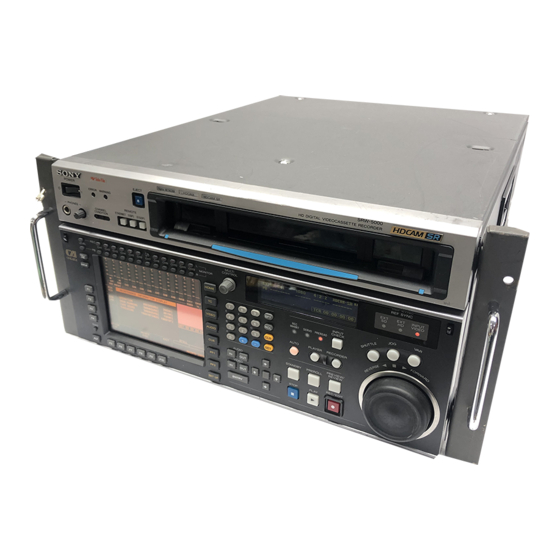
- Page 1 HD DIGITAL VIDEOCASSETTE RECORDER SRW-5000 SRW-5500 FORMAT CONVERTER BOARD HKSR-5001 DIGITAL BETACAM PROCESSOR BOARD HKSR-5002 RGB PROCESSOR BOARD HKSR-5003 OPERATION MANUAL [English] 1st Edition (Revised 4)
-
Page 2: Important Safety Instructions
Important Safety Instructions • Read these instructions. • Keep these instructions. • Heed all warnings. • Follow all instructions. • Do not use this apparatus near water. • Clean only with dry cloth. • Do not block any ventilation openings. Install in accordance with the manufacturer’s instructions. - Page 3 Directive (73/23/EEC) issued by the Commission of the European Community. Compliance with these directives implies conformity to the following European standards: • EN60065: Product Safety (For SRW-5000/5500) • EN55103-1: Electromagnetic Interference (Emission) • EN55103-2: Electromagnetic Susceptibility (Immunity) This product is intended for use in the following...
-
Page 4: Table Of Contents
Chapter 2 Locations and Functions of Parts Chapter 3 Setting Up the VTR Table of Contets 1-1 Features ... 9 1-1-1 Features of the SRW-5000/SRW-5500...9 1-1-2 Features of the Control Panel...11 1-2 Optional Accessories ... 13 1-3 Using the CD-ROM Manual ... 13 1-3-1 CD-ROM System Requirements...13... - Page 5 Chapter 4 Menu Settings 4-1 Registering and Storing Menu Settings ...37 4-1-1 Menu Configuration ...37 4-1-2 Changing Menu Settings ...37 4-1-3 Registering Items to the VTR SETUP Menu...38 4-1-4 VTR Memory Bank Function ...39 4-1-5 Memory Stick Operations ...41 4-1-6 Adding Titles to the Data ...46 4-1-7 Details on VTR Memory Bank and Memory Stick Functions ...46 4-1-8 Memory Stick Data Compatibility ...47...
- Page 6 Chapter 5 Recording/Playback Table of Contets 4-3-11 Superimposition of Character Information (PD CHARA/ CHARA SUPER/H-POS/V-POS)...64 4-4 CUE Menu ... 68 4-4-1 Selecting a Multi-Cue Mode...69 4-4-2 Registering Cue Points...69 4-4-3 Erasing Cue Point Data...71 4-4-4 Prerolling to a Cue Point...71 4-4-5 Changing a Cue Point Into an Edit Point ...72 4-4-6 Backspace Editing...72 4-4-7 TELE FILE Menu ...72...
- Page 7 Chapter 6 Editing Appendix 5-1-4 Simultaneously Monitoring Playback of Video and Audio Signals Being Recorded ...105 5-1-5 Audio Level Meter Display Modes...105 5-2 Recording...106 5-3 Preparing for Playback ...107 5-3-1 Setting Switches and Menus ...107 5-3-2 Adjusting the Audio Playback Level ...107 5-3-3 Selecting the HD-SD Conversion Mode ...108 5-4 Playback ...109 5-4-1 Normal-Speed Playback...109...
- Page 8 Table of Contets Error Messages and Warning Messages ... 134 Error Messages ...134 Warning Messages...135 Error Log Menu ...137 Glossary... 139 Menu List ... 141 Items Relating to VTR Operations (Nos. 001 to ...)... 141 Items Relating to Operation Panels (Nos. 101 to ...) ...145 Items Relating to Remote Interface (Nos.
-
Page 9: Features
LSIs for signal processing and is comparable to the HDCAM HDW-F500 in size, weight and functionality. The SRW-5500 only is a recorder supporting both the HDCAM-SR and HDCAM formats. 1) HDCAM is a trademark of Sony Corporation. - Page 10 HKSR-5002 (option). Video and audio confidence heads Video and audio (channels 1 through 12, or 4 channels for the HDCAM format (SRW-5500 only)) signals can be recorded and simultaneously played back to check the recording. Internal time code generator and reader...
-
Page 11: Features Of The Control Panel
VTR by an external control unit. The VTR also comes with 9-pin REMOTE 1-IN(9P) and REMOTE 1-I/O(9P) connectors to support bridge connection of multiple SRW-5000/5500 units or other VTRs equipped with 9-pin remote connectors for simultaneous operation. Furthermore, you can control the VTR from an external control unit with a parallel (50-pin) interface. - Page 12 A full range of editing functions Two SRW-5000/5500 units can be connected allowing automatic or manual assembe and insert editing. The VTR also features a full range of editing functions, including preview, review, preroll, and the setting or changing of edit points.
-
Page 13: Optional Accessories
1-2 Optional Accessories The following accessories can be used with this unit. HKSR-5001 Format Converter Board This allows format conversion described below: • 2-3 pulldown (23.98PsF to 59.94i, 24PsF to 60i) • Conversion between 1080 and 720P • 4:2:2 between 4:4:4 (Conversion of 4:4:4 to 4:2:2 is possible only when the HKSR-5003 is additionally installed.) HKSR-5002 Digital Betacam Processor Board... - Page 14 • You can purchase a new CD-ROM disc to replace one that has been lost or damaged. Contact a Sony service representative. 1-3 Using the CD-ROM Manual...
-
Page 15: Control Panel
Locations and Functions of Parts 2-1 Control Panel The control panel consists of the following sections: • Upper control panel System set-up panel: Access by opening the lower control panel (see page 23) Lower control panel Note Normally operate the unit with the control panel closed. For details of how to open the control panel, for example for system setup, refer to the Maintenance Manual. -
Page 16: Upper Control Panel
2-1-1 Upper Control Panel 1 POWER switch 2 ERROR indicator 3 WARNING indicator POWER ERROR WARNING PHONES CHANNEL ETHERNET 1(9P) 2(50P) CONDITION 7 CHANNEL CONDITION indicators 8 PHONES level control 9 PHONES jack a POWER switch Pressing on the ‘(’ side of this switch powers the unit and lights up the information display (see page 20) and color display (see page 18). -
Page 17: Lower Control Panel
h PHONES level control Adjusts the output level to the PHONES jack. For details, see “5-1-2 Selecting Audio Signals” on page 103. 2-1-2 Lower Control Panel 1 Menu control section 9 DISPLAY button 0 FULL/FINE button qa PB LEVEL button qs REC LEVEL button 8 DIAG button a MONITOR R buttons... -
Page 18: Display Button
VITC, switch DF/NDF, set the time code to be displayed on an external monitor, and so on. VIDEO button: Press this to go to the VIDEO menu screen. Use it to make video related settings. AUDIO button: Press this to go to the AUDIO menu screen. -
Page 19: Set Button
Press this button again to exit from the recording audio level adjustment mode, and the MONITOR L and R buttons return to the normal status (this status is called the “MONITOR SELECT mode”). 2 Editing control section 1 Numeric buttons and +/– buttons 2 SFT button 3 RCL button 4 CLR button... -
Page 20: Play Button
3 Tape transport control section 1 STANDBY button 2 PREROLL button 3 PREVIEW/REVIEW button PREVIEW/ STANDBY PREROLL REVIEW REC/EDIT STOP PLAY 4 REC/EDIT button 5 PLAY button 6 STOP button a STANDBY button Press this button in other than standby mode to make it light up and place the VTR in standby mode. - Page 21 Displays L1/L2/DID/SDID. This combination is counted as 1 packet. Up to 3 packets can be recorded. On the SRW-5500, the system settings related to recording are shown on the left. If data is detected in the input signal, the L1/L2 values are highlighted. The right side shows playback values detected on the tape.
-
Page 22: Servo Indicator
d SERVO indicator Lights up when the drum servo and capstan servo are locked. e REC INHIBIT indicator Only when this indicator is not lit, you can make settings for assemble/insert editing mode, and carry out recording and playback operations. The status of this indicator depends on the setting of the [F2] (REC INH) button in the HOME menu and the state of the record-protect plug on the cassette. -
Page 23: System Set-Up Panel
2-1-3 System Set-Up Panel Lift the lower control panel up to its horizontal position to access the system set-up panel. CONTROL PANEL connector CONTROL PANEL Card slot eject button Memory stick eject button Memory stick receptacle PCM CIA card slot Harness restraint For details, see “3-4 Using a Memory Stick”... -
Page 24: Connector Panel
2-2 Connector Panel 2 DIGITAL I/O section (see page 27) 1 ANALOG I/O section (see page 25) 3 Remote input/output section 4 Power supply (see page 28) (see page 28) 2-2 Connector Panel... - Page 25 7 HD REF. OUT connectors 8 TIME CODE OUT connector 9 TIME CODE IN connector 0 CUE OUT connector qa CUE IN connector (SRW-5500 only) d REF. INPUT 2 connectors (BNC) and 75Ω termination switch Input a reference video signal of the field frequency selected for the format converter output.
- Page 26 Outputs cue track audio during HDCAM or Digital Betacam playback. Note There is no cue track on an HDCAM-SR tape, and therefore no output. k CUE IN (cue input) connector (XLR 3-31, female) (SRW-5500 only) Enabled only during HDCAM format recording. 2-2 Connector Panel...
- Page 27 2 DIGITAL I/O (input/output) section DIGITAL I/O (AES/EBU) INPUT OUTPUT AUDIO AUDIO CH1/2 CH3/4 CH1/2 CH3/4 CH5/6 CH7/8 CH5/6 CH7/8 CH9/10 CH11/12 CH9/10 CH11/12 a HD SDI (SDI video/audio) INPUT A/B connectors (BNC) These accept SDI video/audio signals. Note The INPUT MONITOR connectors are for use with an input monitor and does not follow the standards for output.
-
Page 28: Power Supply
REMOTE 1-IN(9P) connector (D-sub 9-pin, female) Use this, with the supplied 9-pin remote control cable, to connect the unit to another SRW-5000/5500 unit or another HD VTR unit to carry out editing with a BVE- series editor BVE-900/910/2000/9000/9100. c REMOTE 2 PARALLEL I/O(50P) connector (D- sub 50-pin, female) Inputs an external remote control signal. -
Page 29: Connecting External Equipment
Setting Up the VTR 3-1 Connecting External Equipment 3-1-1 Making HD Digital Connections This example shows the connections when using an HDW- F500 as player and an SRW-5000/5500 as recorder, in 59.94i or 60i mode. HDW-F500 (Player) 9-pin remote control cable a) The figure shows the SRW-5500. -
Page 30: Making Ntsc/Pal Digital Connections
3-1-2 Making NTSC/PAL Digital Connections This example shows how to connect two VTRs, an SRW- 5000/5500 as the player and a DVW-500 D-1 Component Digital VTR as the recorder. SRW-5000/5500 (Player) Input SD OUT COMPOSITE (MONITOR) Video monitor (NTSC/PAL monitor) a) The figure shows the SRW-5500. -
Page 31: Cascade Connection
3-1-3 Cascade Connection This example shows how to connect multiple SRW-5000/ 5500 VTRs together for simultaneous recording. HDW-F500 (Player) TIME CODE OUT TIME CODE IN TIME CODE OUT SRW-5000/5500 (Recorder) TIME CODE IN SRW-5000/5500 (Recorder) Note On the recording VTRs, set the VTR SETUP menu item 613 “TC OUTPUT SIGNAL IN REGENE MODE”... -
Page 32: Reference Signals
3-2 Reference Signals This section describes how reference signals for the video output are selected. 3-2-1 Reference Signals for Output Video Depending on the operating condition, VTR SETUP menu settings, the input signal, and the video output signal from the VTR can be synchronized as follows. Start What is the setting of ext. -
Page 33: Reference Signal Connections
HD: 1080/50i tri-level SYNC signal extrn SD: 625 black burst signal When you have directly connected the input and output connectors of two SRW-5000/5500 units, you can also perform dubbing with the VTR SETUP menu item 005 being set to “input”. -
Page 34: Handling Cassettes
S-size cassette 40 minutes 48 minutes L-size cassette 124 minutes 149 minutes 155 minutes Note HDCAM cassettes are for playback only on the SRW-5000. They can be played back and recorded on the SRW-5500. System frequency 29.97 Hz Digital Betacam cassette S-size cassette... -
Page 35: Preventing Accidental Erasure
Preventing double cassette inserting When a cassette is loaded, an orange lock-out bar appears in the cassette insertion slot to prevent users from attempting to load another cassette. Ejecting the cassette Press the EJECT button. The tape is unthreaded and the cassette is automatically ejected. - Page 36 3-4 Using a Memory Stick turn off the power of the unit or remove the Memory Stick. This may damage the data. Memory Stick and Corporation. MagicGate Memory Stick and Sony Corporation. Labeling position are the trademarks of Sony are the trademarks of...
-
Page 37: Chapter 4 Menu Settings
Menu Settings 4-1 Registering and Storing Menu Settings The operating conditions of the VTR are set using the menu operation section on the lower control panel. Menu items are divided among eight different menus (HOME, TC, VIDEO, AUDIO, CUE, PF1, PF2, SET UP). You can register any frequently used items to the HOME, TC, VIDEO, AUDIO, PF1, and PF2 menu screens. -
Page 38: Registering Items To The Vtr Setup Menu
Press the TC button. The first page of the TC menu appears in the display. P L A Y L O C K T I M E R S E L L T C I N T R P T G A T I M E R R E S E T A I N - - : - - : - - : - -... -
Page 39: Vtr Memory Bank Function
P A G E A L T + H O M E F 1 : 0 0 1 P A E F 2 : Current setting R E A D F 3 : K 1 7 o f f F 4 : F 5 : P A G E F 6 : 3 0 2... - Page 40 Press the SET UP button. The SET UP menu appears in the display. Press the [F1] (VTR BANK) button. The VTR BANK menu appears in the display. V T R B A N K C U R R E N T S E T U P A A A U N D O E D I T...
-
Page 41: Memory Stick Operations
V T R B A N K V T R B A N K C U R R E N T S E T U P S E T U P B A N K 2 ( P r e s e t ) 1 ( P r e s e t ) U N D O 2 ( P r e s e t ) - Page 42 F O R M A T C A R D B A N K 0 C A R D ( B A S E B A L L ) ( P r e s e t ) U N D O ( P r e s e t ) ( P r e s e t ) ( P r e s e t )
- Page 43 The flashing cursor bar indicates the storage destination. To change the title of the bank, press the [F6] (EDIT TITLE) button. For details, see “4-1-6 Adding Titles to the Data” on page 46. Press the [F9] (COPY) button. A message asking you to confirm the operation appears in the display.
- Page 44 A message asking you to confirm the operation appears in the display. Press the [F9] (COPY) button while holding down the SFT button. The VTR stores the cue point list to the memory stick. Press the [F6] (EDIT TITLE) button to add a title to the cue point list.
- Page 45 To change the current VTR menu settings Move the cursor (B) to [C] (CURRENT SETUP). To replace all VTR memory bank contents with memory stick data Press the [F7] (SELECT ALL) button. Note If there are protected items at the destination end, it is not possible to select the [F7] (SELECT ALL) button.
-
Page 46: Adding Titles To The Data
The VTR recalls the cue point list in the memory stick. After the recalling process is completed, the title of the cue point list appears under the CURRENT CUE SET indication Press the [F10] (EXIT) button. The SET UP menu appears again. 4-1-6 Adding Titles to the Data When storing data to a memory bank in a memory stick or the VTR, you can add a title to the data to make data... -
Page 47: Memory Stick Data Compatibility
VTR internally. • There is complete data compatibility between the SRW- 5000 and SRW-5500. However, items which are not available on one model or the other do not appear in the VTR SETUP menu. -
Page 48: Saving And Recalling Default Settings In A "Memory
Make the VTR SETUP menu and PF assignment settings. In the VTR BANK menu screen, save the current settings in any VTR bank. It is preferable to add a title to identify the settings, and protect the settings not to be overwritten. Press the ALT button. - Page 49 DEFAULT BANK is copied from the title of CURRENT SETUP. • There is complete data compatibility between the SRW-5000 and SRW-5500. On how to check the items for which DEFAULT values have been changed from FACTORY PRESET values, see “To check the items for which DEFAULT values...
-
Page 50: Home Menu
Operation mode Servo lock status Tape format Tape running speed Name of the displayed menu H O M E Remaining tape amount Settings PB, EE on, off on/off (SRW-5500 only) off, video, audio, a/v 0 to 30 s on, off... -
Page 51: Selecting The Output Signals (Pb/Ee)
Selecting the insert edit mode Press one of the following INSERT buttons in the HOME menu: [F4] (INS TC), [F5] (INS VIDEO), [F6] (INS AUDIO), [F7] (INS CUE (SRW-5500 only)). For more information about editing operations, see “Chapter 6 Editing” on page 115. -
Page 52: Preread Settings (Pre Read)
For detail on the procedure for DMC playback, see “5-4- 4 DMC Playback” on page 111. During tape editing using two SRW-5000/5500 VTRs, you can use DMC playback to control the playback speed of the player VTR for editing at variable speeds (DMC... -
Page 53: Setting The Stop Code (Stop Code)
For detail on the procedure for DMC editing, see “6-2-1 DMC Editing” on page 126. 4-2-8 Setting the Stop Code (STOP CODE) You can select the stop code detection mode (recording/ confirmation/deletion), and adjust the stop position when a stop code is detected. To call up the STOP CODE menu screen Press the ALT/[F8] (STOP CODE) buttons in the HOME menu. - Page 54 Press the ALT/[F8] (STOP CODE) button. The STOP CODE menu screen appears. Press the [F4] (DETECT ADJUST) button. The setting display lights up. Change the setting with the cursor R or r button. You may also use the MULTI CONTROL knob. Press the [F4] (DETECT ADJUST) button.
- Page 55 Section to insert time code Tape UB “0” 3 frames 20 frames (STOP CODE before deletion) Press the HOME button. The HOME menu screen appears. Press the ALT/[F8] (STOP CODE) buttons. The stop code menu screen appears. Press the [F8] (CODE ERASE) button to select “on”. Pressing the button toggles betwen “on”...
-
Page 56: Tc Menu
4-3 TC Menu The TC menu allows you to set time code-related items through a single menu. The HOME, TC, VIDEO, AUDIO, PF1 and PF2 menus show information that includes the VTR operation mode, time code of the current position, and the time code type, etc. -
Page 57: Setting The Time Data (Timer Sel/Reset/Set/Hold)
4-3-1 Setting the Time Data (TIMER SEL/RESET/SET/HOLD) The display shows the following types of time data: Indication Superimposed Time data type display TCR LTC The LTC the time code reader during playback. TCR VITC The VITC the time code reader during playback. - Page 58 Selecting the time code and the user bits to be recorded Use the [F6], [F7], and [F9] buttons in the TC menu to specify the time code and the user bits to be recorded. The specifications for the various button settings are shown in the following table.
- Page 59 Data entry window P L A Y L O C K T I M E R S E L L T C I N T R P I N T R P T C R T I M E R R E S E T A I N - - : - - : - - : - - A O U T - - : - - : - - : - -...
-
Page 60: Setting The Time Code Reader (Tcr Sel)
To pause the current time Press the [F4] (TIMER HOLD) button. The time is paused only while the button is held down. 4-3-2 Setting the Time Code Reader (TCR SEL) Press the [F5] (TCR SEL) button to select the time code to be read by the time code reader during playback. -
Page 61: Selecting The Drop Frame Mode (Df/Ndf)
4-3-5 Selecting the Drop Frame Mode (DF/NDF) Press the [F9] (DF/NDF) button to select the running mode for the CTL counter and the time code generator. DF: Drop frame mode (DF is displayed.) NDF: Non-drop frame mode (NDF is displayed.) auto: The unit switches to drop frame mode when the field frequency is 29.97 Hz, and switches to non-drop frame mode when the field frequency is 30 Hz. -
Page 62: (Tcconv Menu)
The selected time code is framed with the thick line. Each press of the button switches time code between 24F and 30F. 24F: Presets the 24 frames time code. The A frame of the pulldown sequence is preset. 30F: Presets the 30 frames time code. The A frame of the pulldown sequence is preset. - Page 63 S T A R T I N G T C J U M P I N G C O N V C U R R E N T O R G T C d i s p S T A R T S T A R T J U M P T C P S T...
-
Page 64: Displaying The Pulldown Time Code (Pdtc Disp) (When Hksr-5001 Is Installed)
S T A R T I N G T C J U M P I N G T C C O N V M E N U C U R R E N T O R G T C D I S P S T A R T S T A R T J U M P... - Page 65 Meaning Symbol UBR. VITC reader user bit data Time code data from the time code generator User bit data from the time code generator The duration between any two of the four edit points (IN, OUT, AUDIO IN, and AUDIO OUT) Note When time data or user bits are not read correctly, a “*”...
- Page 66 Display A block B block TAPE UNTHREAD STANDBY OFF T.RELEASE STOP PREROLL PLAY PLAY LOCK PLY-SPD Speed shift from normal speed (%) LOCK EDIT EDIT LOCK STILL SHUTTLE (speed) (speed) (speed D-PREV (speed DMC EDIT DMC-SPD (speed) PREVIEW AUTO EDIT REVIEW a) Initial speed or memorized speed To display a warning message...
- Page 67 When remaining time is 23 minutes. T C R When remaining time is five minutes. T C R When remaining time to is 100 minutes or over. T C R Changing the superimpose position The superimpose position can be set to 16 different positions in the horizontal directions (0 to 15) and 24 different positions in the vertical directions (0 to 23).
-
Page 68: Cue Menu
4-4 CUE Menu Cue points can be registered in a total of 10 pages (numbered 0 to 9), to a total of 100 cue points (numbered 0 to 99). Each page can hold a maximum of 10 cue points. Cue point settings, deletions, and page settings are done through the CUE menu. -
Page 69: Selecting A Multi-Cue Mode
4-4-1 Selecting a Multi-Cue Mode The SRW-5000/5500 has the following two multi-cue modes. PAGE mode Press the ALT/[F8] (PAGE MODE) buttons. In PAGE mode, cue point data can be accessed by page number, thus speeding up cue point registration and cuing operations. - Page 70 P R E V [ ( B l a n k ) E O S [ - - : - - : - - : - - ] P A G E P A G E : 0 0 0 : 0 1 : 1 0 : 0 0 1 0 0 : 0 2 : 1 0 : 0 0 N E X T 2 0 0 : 0 3 : 1 0 : 0 0...
-
Page 71: Erasing Cue Point Data
P R E V [ ( B l a n k ) E O S [ 0 0 : 1 3 : 0 0 : 0 0 ] P A G E P A G E : 1 0 0 0 : 1 0 : 0 0 : 0 0 1 1 0 0 : 1 1 : 0 0 : 0 0 N E X T 1 2 0 0 : 1 2 : 0 0 : 0 0... -
Page 72: Changing A Cue Point Into An Edit Point
Prerolling to a cue point Press the ALT/[F8] (PAGE MODE) buttons or the ALT/[F9] (EXTEND MODE) buttons. If you selected PAGE mode, press the [F1] (PREV PAGE) button or [F2] (NEXT PAGE) button to select a desired page (or use the numeric buttons to enter the page number in the data entry window, then press the [F8] (PAGE SET) button). - Page 73 In HDCAM format: When an MLB-1M-100 memory label (optional) is attached to the cassette, this screen allows operations to read out, enter, or change the cue point information, log (IN/OUT point) information, management information, and so on. Using this information, cassette tape management and tape editing efficiency can be improved.
- Page 74 e REC DATE Displays the date the memory label contents were last modified. f Date/Time Displays the recording date and time. g Duration Displays the recording duration. h File Name Displays the names of files. When the TELE FILE menu display 2 is displayed, you can press the SFT button to switch the TAPE FORMAT display between “59i 1080 422”...
- Page 75 Press the [F7] (SET LETTER) button or the cursor center button. The selected character is entered. F O R M A T R E C D A T E [ 2 0 0 3 / 0 2 / 2 5 ] E O S [ - - : - - : - - : - - ] T - F i l T I T L E [ S O N Y...
- Page 76 State of the already-entered IN point data IN point data has not been Data is not entered updated Updating File Name data To update File Name data, press the cursor t button several times. To update data With the cursor buttons, align the cursor with the File Name data you want to update.
- Page 77 To delete a line To delete a line, with the cursor buttons align the cursor with the line to be deleted, hold down the SFT button, and press the [F5] (DEL POINT) button. This deletes the line, and renumbers the lines following the deleted line. To display other information To display other information, press the [F8] (TAPE INFO) button.
- Page 78 C U E R E C D A T E [ 2 0 0 3 / 0 2 / 2 5 ] S C A N T I T L E [ N o . E N T R Y P O I N T 0 0 : 1 4 : 1 6 : 0 5 I N O U T...
- Page 79 off: Clear write protection for the whole TELE FILE menu. To change the TITLE data Press the ALT/[F3] (ATTRIB EDIT) buttons. With the cursor R or r button, select “TITLE”, and press the ENTRY button. With the cursor T or t button, select the character to be entered.
- Page 80 C U E R E C D A T E [ 2 0 0 3 / 0 2 / 2 5 ] S C A N T I T L E [ S O N Y D e l e t e C u e P o i n t : N o .
- Page 81 To move the cursor using the numeric buttons Enter the line number using the numeric buttons. Then press the [F9] (CUENUM POINT) button. The cursor will move to the line specified by the numeric buttons. Use the numeric buttons to enter the time data in the data entry window, and then press the SET button.
- Page 82 Automatic time data changes during IN/OUT point data entry or modification The table below shows the automatic changes that occur in time data when either the IN point or OUT point is changed. When IN point data is entered or modified: Status of input data IN point The time sequence of the IN/...
- Page 83 R E C D A T E [ 2 0 0 3 / 0 2 / 2 5 ] E O S [ 0 1 : 0 1 : 0 2 : 0 8 ] C U T N o . E D I T T I T L E [ i s p l a y S a m p l e N o .
- Page 84 To change a character Press the cursor R button to move the cursor to the scene data to be changed. Then press the cursor T or t button to move the insertion position. Press the [F10] (SAVE/EXIT) button. The screen that was on before the scene data was entered is displayed again.
- Page 85 To start the procedure over again Press the [F9] (CANCEL) button to start again. To change a character Press the cursor R button to move the cursor to the comment to be changed. Then press the cursor T or t button to move the insertion position. If the entered text is longer than the comment box t or T appears to the left or right of the box.
- Page 86 C U E R E C D A T E [ 2 0 0 3 / 0 2 / 2 5 ] S C A N T I T L E [ T A P E I N F O R M A T I O N N o .
-
Page 87: Video Menu
4-5 VIDEO Menu In the VIDEO menu, adjust the video signal. The VIDEO menu screen shows the VTR operation mode, current position time code, time code type, and so on. About HD image quality adjustments When playing back tapes recorded in Y/P format, HD image quality adjustments are enabled for the HD SDI OUTPUT 1, 2, and MONITOR connectors. -
Page 88: Selecting The Reference Signal (Servo Ref)
4-5-1 Selecting the Reference Signal (SERVO REF) Press the [F2] (SERVO REF) button to select the signal to be used as the reference signal for VTR operations. ext: The servo reference signal is forced to be EXT. input: The signal from the HD SDI INPUT A/B connector is used as the reference signal for VTR operations. - Page 89 ALT/[F8] button BLK LV (ALL): Pressing this button makes it active, and the cursor R and r buttons increase or decrease the value by 1. You can also change the setting with the MULTI CONTROL knob. ALT/[F9] button SETUP (CST): Pressing this button makes it active, and the cursor R and r buttons increase or decrease the value by 0.1.
- Page 90 prst: 100% (4000H) Numerical value: 0.0 (0H) to 141.3% (5A70H) Adjustable range: 0.0% to 141.3% This setting can also be carried out in the VTR SETUP menu item 740 “VIDEO GAIN (ALL)”. Adjusting the chroma gain output level (HD/SD) Make this adjustment with the ALT/[F6] (CRM GA (ALL)) buttons.
-
Page 91: Audio Menu
4-6 AUDIO Menu In the AUDIO menu, make audio signal adjustments. The AUDIO menu screen shows the VTR operation mode, current position time code, time code type, and so on. Indication Button [F1] AUDIO IN [F3] DIGOUT EXCHNG [F4] ANAOUT EXCHNG [F5] SDOUT EXCHNG ALT/[F1]... -
Page 92: Selecting The Audio Input Signal (Audio In)
number on the tape. In this case, if SDOUT EXCHNG is set to “dis”, the button is also highlighted in orange. • The button in the AUDIO menu is highlighted in [F4] orange if even one of the ANALOG audio output channels does not match the corresponding track number on the tape. -
Page 93: Analog Audio Output Signal Source Track Selection
This returns to the AUDIO menu screen. To make output settings for individual channels with the F buttons By pressing any of the [F1] (DIGOUT CH1 TR1) to [F8] (DIGOUT CH8 TR8) buttons menu, and the [F1] (DIGOUT CH9) to [F4] (DIGOUT CH12) buttons in the ALT+DIG OUT screen obtained by pressing the ALT button, you can select the source track for each channel. -
Page 94: Audio Transition Type Selection For Digital Audio Editing
Select the digital audio output signal for each channel. TR1 to TR2: Output the audio signals recorded on tracks 1 to 12. Press the [F10] (EXIT) button. This returns to the AUDIO menu. Making output settings for individual channels with the F buttons By pressing any of the [F1] (SDOUT CH1 TR1) to [F8] (SDOUT CH8 TR8) buttons, you can select the source track for each channel. -
Page 95: Replace)
4-6-7 External Device Digital Audio Edit Preset Command Replace Mode Selection (AUDIO EDIT PRESET REPLACE) You can replace the channel settings for digital audio edit preset commands received from editors and other external devices. For example, some devices are capable of issuing digital audio edit preset commands only for channels 1 to 4 (CH1 to CH4). - Page 96 23.98/24 frame y 25 frame, 29.97 frame y 30 frame), you can set up group relations between audio channels. Press the ALT/[F5] (PITCH GROUP) buttons. The PITCH CORRECTION GROUP SELECT menu appears, together with an image window of channels groups for pitch correction. C H 1 P I T C H C O R R E C T I O N G R O U P S E L E C T G r p _ A...
-
Page 97: Set Up Menu
4-7 SET UP Menu In the SET UP menu, you can store and recall menu settings to and from the VTR memory banks and memory stick, register items to the PF menu, and set items in the VTR SETUP menu and PANEL SETUP menu. For details on storing and recalling data to or from the VTR memory banks or memory stick, and registering items to the PF menus, see “4-1 Registering and Storing Menu... -
Page 98: Vtr Setup Menu
When the ALT/[F8] (REMOTE 9-PIN) buttons are set to “on” You can operate the VTR with a device connected to the REMOTE 1-IN(9P) or REMOTE 1-I/O(9P) connector. When the ALT/[F9] (REMOTE 50-PIN) buttons are set to “on” You can operate the VTR with a device connected to the REMOTE 2 PARALLEL I/O(50P) connector. - Page 99 Scrolling items in the VTR SETUP menu Press the R and r buttons to scroll the items in the VTR SETUP menu. To search the menu by category Items in the VTR SETUP menu are divided into categories according to type of settings they perform. Category Menu number Nos.
-
Page 100: Panel Setup Menu
To continue with changing the settings, repeat steps 1 to 5. Press the [F10] (SAVE/EXIT) button. This saves all the changes, and returns to the SET UP menu screen. To check the items with changed settings In VTR SETUP menu item 131 “CHANGED MENU HIGHLIGHT”, set ITEM SETTING to “on”. - Page 101 Button Indication Function [F1] KEYINH Disables all button operations. [F6] KEY BEEP Sets the keyboard sound. [F7] ALARM BEEP Sets the alarm. [F8] SCREEN Sets the color display screen-saver. SAVER [F9] SCREEN Sets the information display screen-saver. SAVER S [F10] EXIT Returns to the PANEL SETUP menu.
-
Page 102: Chapter 5 Recording/Playback
Recording/Playback 5-1 Preparing for Recording 5-1-1 Setting Switches and Menus Before recording, set the switches and menus as shown in the diagram below. For details, see the pages indicated in the parentheses. REMOTE buttons: None of these buttons light up. POWER switch: ON Menu settings [F2] (REC INH) button in the HOME menu: off... -
Page 103: Selecting Audio Signals
5-1-2 Selecting Audio Signals This section describes how to select the audio signals for input and monitoring. Selecting the audio input signals Proceed as follows to select the audio input signal and channels. Press the AUDIO button, and in the AUDIO menu press the [F1] (AUDIO IN) button, to access the AUDIO INPUT menu. -
Page 104: Adjusting The Recording Level
Selecting non-audio data as the audio input signal Do the procedure below to select non-audio data such as a Dolby E or Dolby Digital (AC-3 input signal. Use the VTR SETUP menu item 831 “NON AUDIO SELECT” to select the audio input signal. 1) Dolby is a trademark of Dolby Laboratories. -
Page 105: Signals Being Recorded
SRW-5000: Cassette format used HDCAM- HDCAM-SR 12ch 12ch HDCAM/ 4ch+CUE D-BETACAM SRW-5500: Cassette format used HDCAM- HDCAM-SR 12ch 12ch HDCAM/ 4ch+CUE D-BETACAM HDCAM HDCAM-SR 4ch+CUE 12ch... -
Page 106: Recording
5-2 Recording To record, follow the procedure below. Check that the REC INHIBIT indicator is off, then insert a cassette. For details on inserting a cassette, see “3-3-2 Inserting and Ejecting Cassettes” on page 34. Press the PLAY button while holding down the REC/ EDIT button. -
Page 107: Preparing For Playback
5-3 Preparing for Playback 5-3-1 Setting Switches and Menus Before starting playback, set the switches and menus as shown in the diagram below. For details, see the pages indicated in the parentheses. POWER switch: ON PB level controls: Playback level 5-3-2 Adjusting the Audio Playback Level Press the PB LEVEL button at the upper left of the... -
Page 108: Selecting The Hd-Sd Conversion Mode
To adjust the audio playback level manually In the PB LEVEL adjustment mode, make the channel active, then adjust to the desired volume with the MULTI CONTROL knob or cursor R and r buttons. When you exit the PB LEVEL adjustment mode, the vertical white line on the right of the audio level meter and a horizontal white line indicating the setting are displayed, indicating that the playback level is subject to manual adjustment. -
Page 109: Playback
5-4 Playback There are four types of playback: • Normal-speed playback • Jog/Shuttle/Variable mode playback • Capstan override playback • DMC (Dynamic Motion Control) playback 5-4-1 Normal-Speed Playback Follow the procedure below to play back at normal speed. Insert a cassette. For details on inserting a cassette, see “3-3-2 Inserting and Ejecting Cassettes”... -
Page 110: Variable Mode Playback
For details on switching the search dial functions, refer to the Maintenance Manual Volume 1. Shuttle mode playback Follow the procedure below to play back in shuttle mode. Press the SHUTTLE button, turning it on. The VTR enters still-picture mode. Rotate the search dial in the desired playback direction and set the angle of rotation as required to obtain the desired playback speed. -
Page 111: Capstan Override Playback
the VTR SETUP menu item 101 “SELECTION FOR SEARCH DIAL ENABLE”. 5-4-3 Capstan Override Playback When playing back the same program on two VTRs, you can adjust the playback phases of the two VTRs so that they are synchronized. There are two ways to make this adjustment: (A) Using the search dial (B) Using the +/–... -
Page 112: Playing Back Non-Audio Data
The tape is prerolled and played back at the initial speed from the preroll point to the speed variation start point. The moment the tape passes the speed variation start point, the MEMORY indicator in the display starts flashing. (The x indicator appears in the time data display window, indicating that tape speed memorization in DMC mode is active.) Rotate the search dial to the position for the desired... -
Page 113: Performing Program Play
Note The program play function is available only when all of the following conditions are met. • Combination of SRW-5000/5500 and HKSR-5001 serial numbers: SRW-5000/5500: Serial No. 12001 or higher HKSR-5001: Serial No. 11001 or higher • Tape format: HDCAM-SR •... - Page 114 Mode2: Search for zero-cross points in the same way as Mode1, but connect zero-cross points only when low- level samples are detected around the zero-cross points. Mode3: At a regular interval corresponding to the playback speed, connect the audio data before and after the processing target with a cross fade.
-
Page 115: Chapter 6 Editing
Editing 6-1 Basic Automatic Editing 6-1-1 Overview of Automatic Editing Automatic edit modes The VTR provides the following two modes for automatic editing: Assemble mode New scenes are added to the end of previously recorded scenes. CTL signals, time codes, video and audio signals on tape in the player are recorded onto tape in the recorder VTR. -
Page 116: Setting Switches And Menus
6-1-2 Setting Switches and Menus Before editing, set the following switches and menus as shown below. POWER switch: ON Recording level indication: recording levels [F1] (TIMER SEL) button in the TC menu: TC or CTL POWER switch: ON Playback level indication: playback levels 6-1 Basic Automatic Editing REMOTE buttons: None of these buttons light up. -
Page 117: Selecting The Edit Mode
6-1-3 Selecting the Edit Mode Select assemble or insert mode. [F3] (ASSEMBLE) button in the HOME menu [F4] (INS TC) to [F6] (INS AUDIO) buttons in the HOME menu Press one of the following buttons to select the respective edit mode: •... -
Page 118: Split Editing
Press the SET button to set the input data. P L A Y L O C K P B / E E L T C I N T R P 2 F D T C R R E C I N H o f f A I N 0 0 : 0 1 : 1 0 : 0 0 A O U T 0 0 : 0 2 : 1 0 : 0 0... - Page 119 Press the appropriate INSERT button ([F4] (INS TC), [F5] (INS VIDEO), [F6] (INS AUDIO)). Press the RECORDER or PLAYER button to select the VTR for which edit points are to be set. The button lights up. To locate the edit points, rotate the search dial in jog or shuttle mode.
-
Page 120: Editing Non-Audio Data
AUDIO IN point IN point Recorder VTR Player VTR AUDIO IN point IN point Automatic setting of AUDIO OUT points When the sixth edit point (AUDIO OUT point) is set, the edit point data is activated and the invalid AUDIO OUT points are automatically deleted. -
Page 121: Cuing Up And Prerolling
• Between AUDIO IN and AUDIO OUT points Durations are calculated as follows. • If both IN and OUT points are set, the duration is the time between the points. • If one of the edit points is not set, the duration is set to 00:00:00. -
Page 122: Modifying Edit Points
During previewing, the PREVIEW/REVIEW button lights After previewing, correct the edit points as required, then do the preview again. For details on modifying edit points, see “6-1-9 Modifying Edit Points” on page 122. To stop previewing Press the STOP button. The tape stops immediately. - Page 123 Moving an edit point position with the numeric buttons 4 2 3 Press one of the IN, OUT, AUDIO IN, or AUDIO OUT button while holding down the RCL button. Time data for the edit point appears in the data entry window.
-
Page 124: Performing Automatic Editing
6-1-10 Performing Automatic Editing Overview Once you have set the necessary edit points, the AUTO button lights up to show that the VTR is ready for automatic editing. Preroll point Recorder VTR Preroll Playback mode Player VTR a) Preroll time: Factory-set to 5 seconds. Can be set from 0 to 30 seconds, in units of seconds, through the VTR SETUP menu. - Page 125 Monitoring signals during editing During editing, you can monitor the following video and audio signals on a monitor connected to the recorder VTR. • Between preroll and IN points: Playback signal of the recorder VTR can be monitored. • Between IN and OUT points: Playback signal of the player VTR can be monitored in E-E mode.
-
Page 126: Advanced Automatic Editing
6-2 Advanced Automatic Editing This section describes the following advanced editing methods: • DMC editing • Animation editing • Preread editing 6-2-1 DMC Editing ® If your player VTR has DT (Dynamic Tracking) capability, you can perform variable speed editing by controlling the playback speed from the lower control panel. -
Page 127: Animation Editing
Press the PREVIEW/REVIEW and PREROLL buttons at the same time. The tape prerolls and the player VTR begins playing at the initial speed. When the x indicator appears with a beep indicating that the IN point has been passed, rotate the search dial to the desired playback speed(s). - Page 128 Video source Digital video input Video switcher Audio Digital mixer audio input Audio source Notes • In preread editing, if an input video signal is used as the reference signal for the output video signal, oscillation may occur because of loop connections. To avoid this, select the external reference signal for preread editing by setting the VTR SETUP menu item 005 “SERVO/AV REFERENCE select”...
-
Page 129: Manual Editing
6-3 Manual Editing Follow the procedure below to perform manual editing. 4 5,6 Enter jog or shuttle mode to position the tape at a place at least three seconds before the position at which you want to set an edit point. Press the AUTO button to turn it off. -
Page 130: Appendix
Appendix Maintenance Head Cleaning Use the BCT-HD12CL Cleaning Cassette to clean the video and audio heads. Read the instructions included with the cleaning cassette carefully, as improper usage can damage the heads. If you insert the cleaning cassette, it is automatically ejected after a head cleaning operation which lasts for 10 seconds. -
Page 131: Specifications
Specifications General Record format HDCAM-SR (SRW-5000/5500) or HDCAM (SRW-5500) Power requirements 100 to 240 V AC, 50/60 Hz Power consumption 320 W (with all option boards installed) Peak inrush current (1) Power ON, current probe method: 54 A (240 V),... - Page 132 Selecting HD or SD in a menu DIGITAL I/O (AES/EBU) INPUT BNC (6) Specifications CH1/2 to CH11/12 AES/EBU format, unbalanced AUDIO INPUT CUE (SRW-5500 only) XLR, 3-pin, female (1) TIME CODE IN XLR 3-pin, female (1) 0.5 to 18 Vp-p, 10 kΩ, balanced Output connectors...
- Page 133 HKSR-5003 RGB Record Playback Board RMM-110 Rack Mount Adaptor BCT-HD12CL Cleaning Cassette Recommended accessories For details about recommended accessories, contact your Sony service representative. Parallel/serial converters HD-694 ASTRO DESIGN Corporation or equivalent XLR/BNC adaptors BCJ-XP-TRA from CANARE Corporation or equivalent For optionally available AC power cords, refer to the supplied Installation Manual.
-
Page 134: Error Messages And Warning Messages
After the error occurs, eliminate the cause of the error and turn the unit back on. If the error message appears again when the unit is turned on, contact your Sony representative. For more information about eliminating errors, refer to the Maintenance Manual (Volume 1). -
Page 135: Warning Messages
Item number Display TAPE TOP ERROR TAPE END ERROR FAN MOTOR ERROR CC TIME OVER SHIFT TIME OVER POSITION BOTH DETECT THREAD BOTH DETECT DR IF ERROR NVRAM CHECK SUM ERROR SV UNDEFINE ERROR SY UNDEFINE ERROR SY1-SY2 DPRAM ERROR SY-FC DPRAM ERROR SY NVRAM CHECK SUM ERROR SY1-SY2 INTERFACE ERROR... - Page 136 To clear a warning message To cancel the display of a warning message, see “Clearing warning messages” on page 138. Item number Display NO EXTERNAL REFERENCE LOST LOCK NO EXTERNAL REFERENCE ON HD & SD REF ASYNCHRONOUS PLL UNLOCK ON FC NO SDI INPUT VIDEO DATA ERROR AUDIO DATA ERROR...
-
Page 137: Error Log Menu
The inserted cassette cannot be recorded or edited because of system settings (recording format, system line, etc). This display applies only to HDCAM/HDCAM-SR cassettes (SRW-5500 only). Cannot lock because there is no 30 frames/second reference information in 720/59.94p HD SDI input signals. -
Page 138: Clearing Warning Messages
Button Display [F1] PAGE TOP [F2] PAGE END [F3] FULL MSG [F4] ALL CLEAR [F5] WARNING [F6] ERROR [F7] CONDITION [F9] TIME [F10] EXIT ALT/[F8] CANCEL EDIT ALT/[F9] REAL TIME For more information about error log menu settings, refer to the Maintenance Manual. Clearing warning messages Press the ALT/[F8] (CANCEL EDIT) buttons. -
Page 139: Glossary
Glossary AES/EBU format A standard format for the transfer of digital audio signals. In this format, two audio signals can be input/output through one XLR-type connector. Assemble editing An edit mode for adding new scenes to the end of previously recorded scenes. - Page 140 External synchronization A method to maintain color subcarrier phase continuity by performing editing in two-frame units in order to achieve stable video without horizontal fluctuation at the edit points. For editing, a recorder VTR (or master VTR) and a player VTR (or source VTR or slave VTR) are used, and external synchronization is commonly used to...
-
Page 141: Menu List
Menu List This section describes all of the VTR SETUP menu items. The VTR SETUP menu items are divided into the following categories by the function. • Items relating to VTR operations (Nos. 001 to ...) • Items relating to operation panels (Nos. 101 to ...) •... - Page 142 Item number Item SERVO/AV REFERENCE select EXTERNAL REFERENCE select SYNC PLAY LOCAL FUNCTION ENABLE Menu List Setting Function [input] The servo reference is determined by the following menu. auto input: The reference signal is obtained from the HD SDI external INPUT A/B connectors.
- Page 143 Item number Item Setting LOCAL KEY MAP Sub items STOP [disable] enable [disable] PLAY enable REC/EDIT [disable] enable STANDBY [disable] enable [disable] EJECT enable [disable] enable SHUTTLE [disable] enable [disable] enable [disable] PREROLL enable [disable] PREVIEW/ REVIEW enable [disable] AUTO enable [disable] INPUT CHECK...
- Page 144 Item number Item PB/EE SELECT MENU Sub items STAND BY OFF STAND BY ON SHUTTLE AUTO EJECT LEVEL1 (HDCAM-SR) Menu List Setting Function Selects output video and audio signals. PB/MU Selects the video and audio output signals in the “standby [EE/EE] off”...
-
Page 145: Items Relating To Operation Panels (Nos. 101 To
Item number Item AUTO EJECT LEVEL2 (HDCAM) P PLAY Items Relating to Operation Panels (Nos. 101 to ...) Item number Item SELECTION FOR SEARCH DIAL ENABLE REFERENCE SYSTEM ALARM REC INHIBIT LAMP FLASHING Setting Function [off] Selects the tape conditions under which a cassette is LEVEL1 automatically ejected in playback (after approx. - Page 146 Item number Item JOG DIAL RESPONSE KEY INHIBIT VARIABLE SPEED LIMIT IN KEY PANEL CONTROL CTL LOCK IN VAR/ SHTL DT MODE POWER-ON MENU select KEY BEEP ALARM BEEP Menu List Setting Function [type1: -1 to +1] Selects the tape speed (VTR command) characteristics for type2: –2 to + 2 search dial rotation.
- Page 147 Item number Item Setting SCREEN SAVER 3 min 10 min 60 min [off] SCREEN SAVER S [off] [off] WARNING DISPLAY INFO DISPLAY rotation MODE latch [momentary] MULTI CUE CLEAR [on] by inject Tele-File MENU [off] auto popup [not clear] Tele-File THREAD COUNTER clear when format mode...
-
Page 148: Items Relating To Remote Interface (Nos. 201 To
Item number Item STOP CODE FUNCTION Sub items DETECT BEEP DETECT STOP STOP ADJUST REC ADJUST S-LCD DIMMER CHANGED MENU HIGHLIGHT Sub items ITEM SETTING DEFAULT SETTING KNOB MODE Items Relating to Remote Interface (Nos. 201 to ...) Item number Item REMOTE 9-PIN REMOTE 50-PIN... -
Page 149: Items Relating To Editing (Nos. 301 To
Item number Item PARALLEL RUNNING VIDEO REMOTE CONTROL SELECT Sub item 1 IMAGE ENHANCER 2 D2 SETUP REMOTE NETWORK Items Relating to Editing (Nos. 301 to ...) Item number Item EDIT OPERATION MODE PREROLL TIME POSTROLL TIME Setting Function [disable] Selects whether two or more VTRs can be operated enable synchronized. - Page 150 Item number Item VAR SPEED RANGE SYNCHRONIZATION EDIT FIELD select SYNCHRONIZE EDIT PRESET REPLACE MODE SELECT ANALOG AUDIO EDIT PRESET REPLACE Sub items ANALOG AUDIO EDIT PRESET REPLACE FOR ANALOG AUDIO EDIT PRESET REPLACE FOR CH10 ANALOG AUDIO EDIT PRESET REPLACE FOR CH11 ANALOG AUDIO...
- Page 151 Item number Item Setting AUDIO EDIT MODE cut edit [cross fade] fade in/out EDIT RETRY [on] PLAY COMMAND –30 frame DELAY START TIME [0 frame] +30 frame VIDEO PREVIEW [VVV] MODE [SSS] AUDIO PREVIEW MODE Function Specifies the type of editing for digital audio signals. cut edit: Cut editing (discontinuity in audio signal may result at the join, causing noise.) cross fade: Cross-fade (see figure below.)
-
Page 152: Items Relating To Prerolling (Nos. 401 To
Items Relating to Prerolling (Nos. 401 to ...) Item number Item FUNCTION MODE AFTER CUE-UP CUEUP BY TC CUEUP BY CTL CUE MENU DEFAULT MODE select CUE MENU PREROLL OFFSET Menu List Setting Function [stop] Selects the operation mode that the VTR changes to after still completing a cue up operation. -
Page 153: Items Relating To Recording Protection (Nos. 501 To
Item number Item AUTO REWIND AUTO CUE UP Items Relating to Recording Protection (Nos. 501 to ...) Item number Item STILL TIMER TAPE PROTECTION MODE FROM SEARCH TAPE PROTECTION MODE FROM STOP DRUM ROTATION IN STANDBY OFF STILL TENSION Setting Function [off] Selects the rewind mode for the end of the tape. -
Page 154: Items Relating To The Time Code (Nos. 601 To
Items Relating to the Time Code (Nos. 601 to ...) Item number Item DF/NDF MODE select TIMER MODE select TCR MODE select TC2 MODE SEL Menu List Setting Function [drop frame] Selects the timing mode for the time code generator and non-drop frame the CTL counter. - Page 155 Item number Item Setting TAPE TIMER +/– 12H [24H] DISPLAY TCG MODE select [preset] regene auto TCG REGENE SDI-LTC SOURCE select SDI-VITC ext-LTC int-VITC [int-LTC] TCG/UBG REGENE [TC UB] MODE [free run] REC RUN/FREE RUN select rec run [on] DOWNCONVERTER VICT output VITC POSITION-1 12,281 line...
- Page 156 Item number Item VITC POSITION-2 select (NTSC) TC OUTPUT SIGNAL IN REGENE MODE PHASE CORRECTION VITC POSITION-1 select (PAL) VITC POSITION-2 select (PAL) LTC OUTPUT PHASE select EXT LTC MODE SUPERIMPOSED CHARACTER Menu List Setting Function 12,281 line When 29.97PsF/59.94i mode is selected on the VTR, this setting specifies the lines in which the VITC signal is inserted.
- Page 157 Item number Item Setting CHARACTER H- POSITION CHARACTER V- POSITION [22] CHARACTER TYPE without BG outlined translucent [with BG] × 1 CHARACTER SIZE [ 2] DISPLAY time data & status INFORMATION time data & UB select time data & CTL time data &...
-
Page 158: Items Relating To The Video Control (Nos. 706 To
1) A-ROUNDING™ A method for rounding a 10 bit signal to 8 bits. This process suppresses step noise that occurs when lines which differ slightly from the horizontal are displayed. A-ROUNDING is a trademark of Sony Corporation. Menu List Setting Function... - Page 159 Item number Item Setting MASTER LEVEL 0.0% (0H) (HD) preset: 100% [100 (4000H) 141.3% (5A70H) Y LEVEL (HD) 0.0% (0H) preset: 100% (4000H) [100 141.3% (5A70H) LEVEL (HD) 0.0% (0H) preset: 100% (4000H) [100 141.3% (5A70H) LEVEL (HD) 0.0% (0H) preset: 100% (4000H) [100...
- Page 160 Item number Item BLACK LEVEL (ALL) (HD/UC/SD/DC) preset: 100% (4000H) MASTER LEVEL (D1) preset: 100% (4000H) Y LEVEL (D1) preset: 100% (4000H) B–Y LEVEL (D1) preset: 100% (4000H) R–Y LEVEL (D1) preset: 100% (4000H) SETUP LEVEL (CST) preset: 7.5 IRE SYNC PHASE (SD) preset: 0 FINE (SD)
- Page 161 (sub item): When this item is selected, the other items all take the same values. When playing back 4:2:2 DUAL format tapes recorded with the SRW-1 on the SRW-5000/5500, selects whether to play back Stream-A or Stream-B. Stream-A: Play back the video of Stream-A.
-
Page 162: Items Relating To The Audio Control (Nos. 807 To
Items Relating to the Audio Control (Nos. 807 to ...) Item number Item AUDIO MONITOR-L select Sub items A-MON CH1 A-MON CH2 A-MON CH3 A-MON CH4 A-MON CH5 A-MON CH6 A-MON CH7 A-MON CH8 A-MON CH9 A-MON CH10 A-MON CH11 A-MON CH12 Menu List Setting... - Page 163 Item number Item Setting AUDIO MONITOR-R select Sub items [disable] A-MON CH1 enable A-MON CH2 disable [enable] [disable] A-MON CH3 enable A-MON CH4 [disable] enable A-MON CH5 [disable] enable A-MON CH6 [disable] enable A-MON CH7 [disable] enable A-MON CH8 [disable] enable A-MON CH9 [disable]...
- Page 164 Item number Item LEVEL METER SCALE AUDIO OUTPUT PHASE preset: 128 PITCH CORRECTION Menu List Setting Function [peak 0 dB] Specifies the mode in which the digital audio level is reference 0 dB displayed. peak 0 dB: Displays minus audio levels with the maximum level set at 0 dB.
- Page 165 Item number Item Setting PITCH CORRECTION GROUP select Sub items PITCH [Grp-A] Grp-B Grp-C CORRECTION Grp-D Grp-E Grp-F OFF GROUP select CH1 [Grp-A] Grp-B Grp-C PITCH CORRECTION Grp-D Grp-E Grp-F OFF GROUP select CH2 PITCH Grp-A [Grp-B] Grp-C CORRECTION Grp-D Grp-E Grp-F OFF GROUP select CH3 Grp-A [Grp-B] Grp-C PITCH...
- Page 166 Item number Item PITCH CORRECTION DETECT MODE select Sub items PITCH CORRECTION DETECT MODE select Group-A PITCH CORRECTION DETECT MODE select Group-B PITCH CORRECTION DETECT MODE select Group-C PITCH CORRECTION DETECT MODE select Group-D PITCH CORRECTION DETECT MODE select Group-E PITCH CORRECTION DETECT MODE...
- Page 167 A-REC LEVEL CH11 A-REC LEVEL CH12 A-REC LEVEL CUE (SRW-5500 only) Function Selects a non-audio input signal. The setting is in units of stereo pairs. When this is set to other than “off”, the setting of item 830 is invalid.
- Page 168 Item number Item AUDIO PB LEVEL Sub items A-PB LEVEL CH1 A-PB LEVEL CH2 A-PB LEVEL CH3 A-PB LEVEL CH4 A-PB LEVEL CH5 A-PB LEVEL CH6 A-PB LEVEL CH7 A-PB LEVEL CH8 A-PB LEVEL CH9 A-PB LEVEL CH10 A-PB LEVEL CH11 A-PB LEVEL CH12 A-PB LEVEL CUE Menu List...
- Page 169 Item number Item Setting DIGITAL AUDIO OUTPUT EXCHANGE Sub items DIGITAL OUT CH1 [TR1] TR12 DIGITAL OUT CH2 [TR2] TR12 DIGITAL OUT CH3 [TR3] TR12 DIGITAL OUT CH4 [TR4] TR12 DIGITAL OUT CH5 [TR5] TR12 DIGITAL OUT CH6 [TR6] TR12 DIGITAL OUT CH7 [TR7] TR12...
- Page 170 Item number Item DIGITAL OUT CH12 TR1 ANALOG AUDIO OUTPUT EXCHANGE Sub items ANALOG OUT CH1 [TR1] ANALOG OUT CH2 TR1 ANALOG OUT CH3 TR1 ANALOG OUT CH4 TR1 Menu List Setting Function [TR12] Sets the signal track to be superimposed on the analog audio signal output channels 1 to 4.
- Page 171 Item number Item Setting SD AUDIO OUTPUT EXCHANGE Sub items SDOUT EXCG [disable] enable [TR1] SD OUT CH1 TR12 SD OUT CH2 [TR2] TR12 SD OUT CH3 [TR3] TR12 SD OUT CH4 [TR4] TR12 SD OUT CH5 [TR5] TR12 SD OUT CH6 [TR6] TR12 SD OUT CH7...
-
Page 172: Items Relating To Digital Processing (Nos. 902 To
Items Relating to Digital Processing (Nos. 902 to ...) Item number Item FREEZE MODE FREEZE CONTROL FROM KEY PANEL STOP FREEZE CONTROL ACTIVE LINE 1035 CONVERT MODE ACTIVE LINE 1080 CONVERT MODE Menu List Setting Function [field] Specifies the freeze (still-picture) mode and freeze timing field1 during manual freezing (by REMOTE 1-IN(9P) or REMOTE field2... - Page 173 Item number Item Setting SLOW PROCESS [off] MODE SOFT BLANKING [off] ASPECT FLAG OFF [off] [EDGE-CROP] DOWNCONVERTER MODE (DC) LETTER BOX SQUEEZE [16:9] LETTER BOX MODE (DC) 14:9 13:9 H CROP –120 POSITION (DC) preset: 0 CROSS COLOR (DC) preset: 8 DETAIL GAIN (DC) preset: 64 [64] (0 dB)
- Page 174 Item number Item CRISP THRESHOLD (DC) preset: 0 LEVEL DEPEND THRESHOLD (DC) Sub items DEPEND BLACK (DC) DEPEND WHITE (DC) H DETAIL FREQUENCY select (DC) H/V RATIO (DC) preset: 3 GAMMA (DC) GAMMA LEVEL (DC) preset: 0 CROSS COLOR CRISP (DC) preset: 4 V-FILTER SELECT CONVERTER...
- Page 175 Item number Item Setting UP CONVERTER FIELD PROCESS FRAME [ADAPTIVE] ADAPTIVE-2 ADAPTIVE-3 DETAIL GAIN (UC) preset: 64 [64] LIMITTER (UC) preset: 32 [32] CRISP THRESHOLD (UC) preset: 8 LEVEL DEPEND THRESHOLD (UC) preset: 8 H DETAIL 3.2MHz FREQUENCY (UC) 4.5MHz [5.0MHz] 4.0MHz H/V RATIO (UC)
-
Page 176: Items Relating To The Pulldown Control (Nos. A01 To
Item number Item ALPHA CHANNEL LEVEL Stop freeze operation MODE (Before) STILL (dynamic tracking on) CAPSTAN drive (includes shuttling up to Reel drive (includes shuttling over • A “DT picture” is a frozen picture in noiseless DT playback mode. The picture freezes in frame mode when the dynamic tracking is performing a frame operation. - Page 177 Item number Item Setting PD EXT SD REF [off] LOCK MODE lock1 lock2 [off] SUPERIMPOSED TIME CODE ID PD CHARACTER [off] 24F TIME CODE MODE FC REFERENCE extrn HD [extrn SD] select Function When the operating frequency is set to 23.98PsF, specifies whether or not the pulldown output signal and down- converted output signal are synchronized with the reference signal by the REF.
-
Page 178: Other Items (Nos. T01 To
Item number Item TC sense data select Other Items (Nos. T01 to ...) Item number Item AUTO REPEAT MODE INTERNAL VIDEO SIGNAL GENERATOR (HD) INTERNAL AUDIO SIGNAL GENERATOR Note Items T01, T02, and T04 are reset to their factory default settings whenever the power is turned off. - Page 179 Recording and playback formats Recording and playback formats: Cassette type HDCAM-SR HDCAM (playback only on SRW-5000) Recording formats: Cassette type Digital Betacam (optional HKSR-5002 required) a) When the number of valid input signal lines is 1035, the system detects this and automatically selects 1035 recording mode.
- Page 180 Recording tape format conversion outputs System 1080 frequency Recording 23.98PsF 24PsF tape format 1080 23.98PsF 24PsF 25PsF 29.97PsF 30PsF 59.94i 59.94P a: Normal playback of video, audio, and time code possible. z: 0.1% off-speed playback of video, audio, and time code possible. f: Off-speed playback of video and audio possible.
- Page 181 Recording and playback tape formats and conversion output Cassette type Recording/playback mode HDCAM or HDCAM-SR 1080/4:2:2 1035/4:2:2 HDCAM-SR 720/4:2:2 Digital Betacam 1080/4:2:2 720/4:2:2 1080/4:2:2 720/4:2:2 HDCAM-SR 1080/4:4:4 a) Optional HKSR-5001 required. b) Optional HKSR-5002 required. c) Optional HKSR-5003 required. d) When the system setting is 1080, only playback is possible. e) When the system setting is 720, only playback is possible.
- Page 182 Relation between HKDV-900/503 setting items and setup menu items of this unit In the cells of the “Setup menu items of this unit” column, the brackets indicate available outputs. Setup menu items of this unit HKDV-900/503 setting items HD Master 708: MASTER LEVEL (HD) [HD/UC] HD Y 709: Y LEVEL (HD) [HD/UC]...
-
Page 183: Index
Index AC IN connector 28 Adjusting audio playback level 107 output video signal 88 Advanced Automatic Editing 126 ALT button 18 Assemble mode 115 AUDIO IN/OUT buttons 19 AUDIO Menu 91 AUDIO OUTPUT CH1 to CH4 connectors 25 AUTO button 19 Automatic edit modes 115 Automatic editing 115 animation editing 127... - Page 184 Maintenance 130 Manual editing 129 Memory label 10, 11, 73 Memory stick adding titles 46 data compatibility 47 formatting 41 operations 41 recalling 44 storing 42 storing cue point lists 43 Menu changing a CUE point into an edit point 72 configuration 37 control section 17 list 141...
- Page 185 Time code reader (TCR) 60 Time data resetting 59 selecting the time data display 57 setting 57 Upper control panel 16 USB connector 28 User bits setting 59 Using a Memory Stick 35 Using the CD-ROM manual 13 VAR button 22 Variable speed playback 109 VIDEO CONTROL connector 28 VIDEO Menu 87...
- Page 186 The material contained in this manual consists of information that is the property of Sony Corporation and is intended solely for use by the purchasers of the equipment described in this manual. Sony Corporation expressly prohibits the duplication of any...
- Page 187 Sony Corporation SRW-5000/5500 (SY) 3-792-075-05 (1) © 2003...