
Related Manuals for Sony XDCU-50


Summary of Contents for Sony XDCU-50
-
Page 1: Operating Instructions
4-260-666-11 (1) HD Camera Extension Unit Operating Instructions Before operating the unit, please read this manual thoroughly and retain it for future reference. XDCU-50 4260666110 © 2010 Sony Corporation... - Page 2 WARNING To reduce the risk of fire or electric shock, do not expose this apparatus to rain or moisture. To avoid electrical shock, do not open the cabinet. Refer servicing to qualified personnel only. THIS APPARATUS MUST BE EARTHED. Using this unit at a voltage other than 120 V may require the use of a different line cord or attachment plug, or both.
- Page 3 This product is intended for use in the following Electromagnetic Environments: E1 (residential), E2 (commercial and light industrial), E3 (urban outdoors), E4 (controlled EMC environment, ex. TV studio). The manufacturer of this product is Sony Corporation, 1-7-1 Konan, Minato-ku, Tokyo, Japan.
- Page 4 électromagnétiques suivants : E1 (résidentiel), E2 (commercial et industrie légère), E3 (urbain extérieur) et E4 (environnement EMC contrôlé, ex. studio de télévision). Le fabricant de ce produit est Sony Corporation, 1-7-1 Konan, Minato-ku, Tokyo, Japon. Le représentant autorisé pour EMC et la sécurité des produits est Sony Deutschland GmbH, Hedelfinger Strasse 61, 70327 Stuttgart, Allemagne.
- Page 5 (Wohnbereich), E2 (kommerzieller und in beschränktem Maße industrieller Bereich), E3 (Stadtbereich im Freien) und E4 (kontrollierter EMV-Bereich, z.B. Fernsehstudio). Der Hersteller dieses Produkts ist Sony Corporation, 1-7-1 Konan, Minato-ku, Tokyo, Japan. Der autorisierte Repräsentant für EMV und Produktsicherheit ist Sony Deutschland GmbH, Hedelfinger Strasse 61, 70327 Stuttgart, Deutschland.
-
Page 6: Table Of Contents
Table of Contents Overview...7 Features... 7 Using the CD-ROM... 8 Example System Configurations... 9 Names and Functions of Parts ... 11 Preparations and Settings ... 17 Appendix ... 21 Important Notes on Operation... 22 Specifications ... 23 Table of Contents Reading the CD-ROM Manuals ... -
Page 7: Overview
Overview The XDCU-50 HD Camera Extension Unit (called “the unit” below) can be combined with a camcorder fitted with a XDCA-53 or XDCA-55 HD Camera Adaptor and equipment such as a remote control unit to configure a recording and long-distance transmission system. The maximum transmission distance is 100 m (328 feet). -
Page 8: Using The Cd-Rom
Adobe Reader. In such a case, install the latest version you can download from the URL mentioned in “Preparations” above. Note If you have lost or damaged the CD-ROM, you can purchase a new one to replace it. Contact a Sony service representative. Using the CD-ROM... -
Page 9: Example System Configurations
Example System Configurations The following sections provide examples to show how a system can be configured. System including the PMW-320/350/500 and XDCA-55 DXF-C50W/51 Viewfinder PMW-320/350/500 (with the XDCA-55 attached) VCT-U14 Tripod adaptor Portable camera tripod System Including the PMW-EX3 and XDCA-53 Compact-size LCD monitor PMW-EX3 (with the XDCA-53 attached,... - Page 10 Note To check return video signals on the PMW-EX3, you must mount a monitor on the PMW-EX3 or XDCA-53. For information about mountable monitors, contact your dealer or a Sony service representative. Example System Configurations...
-
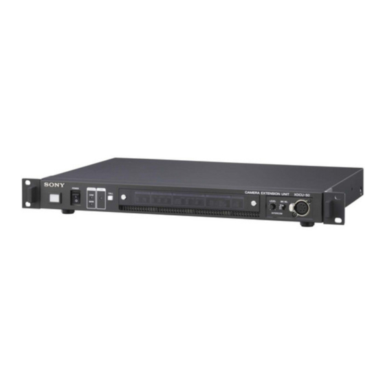
Page 11: Names And Functions Of Parts
Lights in green when the unit is powered on. This unit is equipped with a cooling fan. If the fan fails, this indicator flashes. In this case, power the unit off immediately and contact your dealer or a Sony service representative. d Camera adaptor indicator Lights in green when power is being supplied from this unit to a camera adaptor. - Page 12 i LINK indicator Lights in green when a data transfer link between this unit and a camera adaptor has been established, and when device authentication between the camera adaptor and the camcorder has been established. System setting switches Use the supplied front cover to protect the system setting switches from misoperation.
- Page 13 RETURN INPUT SELECT switches Make settings related to return video signals. Switch name HDSDI/SDSDI/ VIDEO AUTO/ SQUEEZE/ LETTER BOX/ EDGE CROP For details, see “Return Video Signal Input and Output” (page 21). Switch name Settings ASPECT SQUEEZE: Squeeze mode LETTER BOX: Letter box mode EDGE CROP: Edge crop mode DETAIL LEVEL HIGH: High...
-
Page 14: Rear Panel
If you set it to anything other than “4W”, the intercom system may not operate properly. For information about connections to an intercom system, contact your dealer or a Sony service representative. 2 AUX connector 3 GENLOCK INPUT connectors 5 CA connector... - Page 15 For details about the general purpose lines, see “AUX connector” (page 14). For details about the pin assignments of the CA connector, contact a Sony service representative. f - AC IN connector (3-pin) Connect to an AC power source with the specified power cable.
- Page 16 System format (number of Signal format system lines/frame rate) 1080/50i PAL (625/50i) 720/50P The SD analog composite signals output from this connector and the video output pin of the REMOTE connector, and the SDSDI signals output from the OUTPUT SDI connector, are SD signals that have been internally down converted from HD signals by this unit.
-
Page 17: Preparations And Settings
Preparations and Settings Example Connections Connecting to the XDCA-55 CCZ-A cable (Max. 100 m (328 feet)) This unit Connecting to the XDCA-53 CCZ-A cable (Max. 100 m (328 feet)) This unit To fix the connection cables using the cable clamp belt The cables to connect this unit and the camera adaptor can be fixed to the camera or plate by using the cable clamp belt supplied with the camera adaptor. -
Page 18: Attaching Rack Mount Brackets
Belt bracket attachment screws (XDCA-55) Belt bracket (supplied with XDCA-55) Cable clamp belt (supplied with XDCA-55) Bundle the three connection cables with the cable clamp belt. Pass the cables so as to make a loop as illustrated. Adjust the tightening force of the belt to suit the diameters of the cables. -
Page 19: Starting The System
Starting the System Notes • After connecting the system with a CCZ-A and BNC cables, power on the devices as described below. • Do not connect or disconnect the cables connecting this unit and the camera adaptor (CCZ-A and BNC cables) while the system is powered on. -
Page 20: Genlocking The System
Genlocking the System To genlock the system, input a reference sync signal to the input side GENLOCK INPUT connector of this unit. The reference sync signal can be an analog HD signal (tri-level sync) or an analog SD signal (bi-level sync). The reference sync signal input to the input side GENLOCK INPUT connectors is output from the loop-through output side connector (... -
Page 21: Appendix
Appendix Return Video Signal Input and Output Return video signals input to this unit are sent to the camera adaptor as HDSDI signals. The camera adaptor switches between the return video signal received from this unit and the signal received from the camcorder, and outputs the signal from the MONI.OUT connector. -
Page 22: Important Notes On Operation
Fan alarms The POWER indicator flashes at a frequency of 4 Hz when the unit’s cooling fan is not rotating during operation of the unit. Important Notes on Operation Important Notes on Operation Use and storage locations Avoid using or storing the unit in the following places. •... -
Page 23: Specifications
× 11 notice. Note Always verify that the unit is operating properly before use. SONY WILL NOT BE LIABLE FOR DAMAGES OF ANY KIND INCLUDING, BUT NOT LIMITED TO, COMPENSATION OR REIMBURSEMENT ON ACCOUNT OF THE LOSS OF PRESENT OR... - Page 24 Printed in China...