Sony XCD-V60, XCD-SX90, XCD-U100 Technical Manual
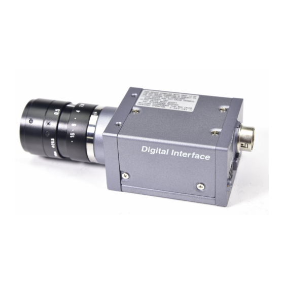
Color and black and white digital camera module
Hide thumbs
Also See for XCD-V60, XCD-SX90, XCD-U100:
- Operating instructions (2 pages) ,
- Technical manual (39 pages) ,
- Service manual (30 pages)

Related Manuals for Sony XCD-V60, XCD-SX90, XCD-U100


Summary of Contents for Sony XCD-V60, XCD-SX90, XCD-U100
- Page 1 A-CUJ-100-11 (1) Digital Camera Module Technical Manual XCD-V60CR/SX90CR/U100CR (Color model) XCD-V60/SX90/U100 (Black and white model) © 2007 Sony Corporation...
-
Page 2: Table Of Contents
Control of IIDC Standard Features ...21 The formula for absolute value shutter control register address ...24 Control of IIDC Optional Features ...25 Control of Sony’s Unique Features ...26 LUT (LookUp Table) ...26 3 × 3 Filter ...27 Display of Test Chart ...27 Trigger Inhibition ...28... -
Page 3: Overview
Overview The six models of the XCD-series digital camera modules (Black and white models and RAW color models) employing the IEEE1394b-2002 standard are equipped with quality digital camera features. Although it is compact, the camera allows high-speed image transfer and daisy chain connection with two IEEE1394b connectors. -
Page 4: System Components
Select an IEEE1394b interface board if you use the transfer speed of 800 Mbps. 5 VCT-ST70I tripod adaptor (Sony) Attach this adaptor to the bottom of the camera module to fix the camera module to a tripod. 6 DC-700/700CE camera adaptor (Sony) -
Page 5: Connection Diagram
Connection Diagram XCD-V60/V60CR/SX90/ SX90CR/U100/U100CR C-mount lens IEEE1394b cable VCT-ST70I Tripod Adaptor Host adaptor card Host equipment (PC, etc.) -
Page 6: Location And Function Of Parts And Operation
Location and Function of Parts and Operation Front/Top/Bottom 1 Lens mount (C-mount) Attach any C-mount lens or other optical equipment. Note The lens must not project more than 10 mm (13/32 inch) from the lens mount. 1 Lens mount face 210 mm (13/32 inch) or less 2 Auxiliary holes (top) 3 Reference holes (bottom) These precision screw holes are for locking the... -
Page 7: Installation
Installation Fitting the lens Remove the lens mount cap. Screw in the lens (not supplied), and turn it until it is secured. Note Clean the optical filter with a commercially available blower brush to remove dust. Using a tripod To use the tripod, install the VCT-ST70I tripod adaptor (not supplied) on the camera module. -
Page 8: Functions
Functions Gain Both Manual and Auto Gain settings are available with this camera. The variable range extends from 0 to 24 dB for the black and white models or from 0 to 18 dB for the color models. The camera is designed so that the gain can be subdivided and set by 0.0359 dB. -
Page 9: Auto Exposure
Auto Exposure AutoExposure is a function that automatically adjusts the gain and shutter settings, based on the brightness of the subject. When the gain or shutter is set to Auto, the brightness is adjusted automatically to the value specified with AutoExposure. Gamma This camera uses the gamma function to select the lookup table. -
Page 10: Trigger
Trigger Trigger shutter is useful for capturing images in response to a trigger that starts the exposure to match a preset timing. It can also be used to capture an image using multiple cameras with the same timing. When a trigger shutter is used, the required trigger is input via the 12-pin connector on the rear panel. -
Page 11: Pan/Tilt
Pan/Tilt Pan/Tilt is a function used to move a camera up and down or left and right. However this camera supports a video mode much smaller than the CCD’s effective pixels by cutting out images from the whole screen. You can specify the portion to be cut out using Pan/Tilt commands. -
Page 12: Strobe Control
Strobe Control A strobe control signal is assigned in the 12-pin connector. This allows direct command of light- emission from the strobe connected to the camera and controls the light-emission timing and the signal width. The output terminal is of the open-collector type and should be pulled at the strobe side. -
Page 13: Memory Shot
Memory Shot The camera is equipped with Memory Shot that temporarily stores an image in the frame memory inside the camera and transfers it later. When multiple cameras are connected in the same bus, all the cameras may not output images at the same time due to the restriction of 800 Mbps band. -
Page 14: Partial Scan
Partial Scan The partial scan is a function for outputting part of a whole image as a region of interest on the whole image. Based on the unit cell as the unit, continuous parts can be selected. Only rectangles can be selected. The screen cannot be cut in convex and L shapes. -
Page 15: Binning Mode
Binning Mode The mode used when the sensitivity is increased and the frame rate is multiplied based on mixing the CCD pixel data, is called the Binning mode. There are two types of binning: 1 × 2 binning when the output image is compressed in the vertical direction only, and 2 ×... -
Page 16: Control
Control Camera Command Status Register This camera complies with IIDC 1394-based Digital Camera Specification, Version 1.31 (hereinafter referred to as IIDC v1.31). The standards document can be purchased from 1394TA (the 1394 Trade Association). As it is very helpful in understanding the explanations in this Technical Manual, we recommend that you purchase a copy of IIDC v1.31. -
Page 17: Configurationrom
The serial number and firmware version of the camera are stored in ConfigurationROM to be used when required. Note that the setting method for the serial number and firmware version information is of Sony’s unique specification and is not compatible with cameras of other manufacturers. - Page 18 Vender Name Leaf 464h 468h 470ch For offset address 464h, the length of the VendorNameLeaf is 3 Quadlets. The subsequent 8 bytes are fixed at 00. After that, the four characters for “SONY” are entered. ModelNameLeaf Offset Model Name Leaf 474h 478h...
-
Page 19: Control Base Address
Control Base Address Every register address is decided based on the base address found in the CommandRegsBase field of ConfigrationROM. F0F00000h is the control base address on this camera. Inquiring about Supported Video Modes First, we will find out what video formats are supported. Data Address XCD-V60/... -
Page 20: Video Mode Settings (S800)
Video Mode Settings (S800) Select the video mode you want to use from the tables, and make the required settings. As examples, the register settings for Format0, Mode5, and a frame rate of 60 fps for the XCD-V60; Format2, Mode2, and a frame rate of 30 fps for the XCD-SX90, and Format2, Mode5, and a frame rate of 15 fps for the XCD-U100 are shown. -
Page 21: Control Of Iidc Standard Features
Control of IIDC Standard Features Before transmitting the control command, check the variable ranges of settings and if there is an automatic mode for each feature. As the variable ranges of the settings vary with video modes for the Pan and Tilt features, be sure to check them if the video mode is changed. - Page 22 Address F0F0051Ch CB00347Eh (Shutter) F0F00520h 8B000***h (Gain) F0F00530h 8C81C003h (Trigger) F0F00534h 89000FFFh (TriggerDelay) F0F00584h 89******h (Pan) F0F00588h 89******h (Tilt) F0F0058Ch 89000***h (OpticalFilter) * According to the IEEE 1394 specifications, the most significant bit is shown as 0, and the least significant bit as 31. Data This feature exists.
- Page 23 Actual control can be carried out by setting registers from F0F00800 onward. ddd indicates the control value expressed as a 12 bit hexadecimal number. xxx indicates that any setting made will be ignored. Brightness control Address Data F0F00800 82000ddd Adjusts the black level. AE reference control Address Data...
-
Page 24: The Formula For Absolute Value Shutter Control Register Address
Pan/Tilt control Address Data F0F00884 82000ddd Sets Pan manually. F0F00888 82000ddd Sets Tilt manually. Optical Filter control Address Data F0F0088C 882000ddd For black and white models, selects 3 × 3 filter. For color models, changes the Bayer pattern. GPIO control Address Data F0F20400... -
Page 25: Control Of Iidc Optional Features
Control of IIDC Optional Features Check if the camera is equipped with optional features by reading bit 3 of BASIC_FUNC_INQ. Address Data F0F00400 9080018F (BASIC_FUNC_INQ) Check the supported feature by reading Opt_Function_Inq. Address Data F0F0040Ch 50000000h Opt_Function Does not support PIO. _Inq Does not support SIO. -
Page 26: Control Of Sony's Unique Features
Control of Sony’s Unique Features LUT (LookUp Table) Enabling writing the Lookup table Write the following three commands in sequence. Address Data F0F30000 08004600 F0F30004 0030FFFF F0F30008 80000000 Disabling writing the Lookup table Write the following three commands in sequence. -
Page 27: 3 × 3 Filter
3 × 3 Filter Enabling writing the filter Write the following three commands in sequence. Address Data F0F30000 08004600 F0F30004 0031FFFF F0F30008 80000000 Disabling writing the filter Write the following three commands in sequence. Address Data F0F30000 08004600 F0F30004 0031FFFF F0F30008 00000000 When writing of the filter is enabled, the addresses... -
Page 28: Trigger Inhibition
Trigger Inhibition Enabling Trigger inhibition Write the following three commands in sequence. Address Data F0F30000 08004600 F0F30004 0032FFFF F0F30008 80000000 Disabling Trigger inhibition Write the following three commands in sequence. Address Data F0F30000 08004600 F0F30004 0032FFFF F0F30008 00000000 User Free Memory Enabling User free memory Write the following three commands in sequence. -
Page 29: Setting Awb (Auto White Balance) Parameters
Setting AWB (Auto White Balance) Parameters Enabling AWB parameter setting Write the following three commands in sequence. Address Data F0F30000 08004600 F0F30004 0034FFFF F0F30008 80000000 The detection frame is highlighted. Disabling AWB parameter setting Write the following three commands in sequence. Address Data F0F30000... -
Page 30: Memory Shot
Memory Shot Switching to Memory shot mode Write the following three commands in sequence. Address Data F0F30000 08004600 F0F30004 0010FFFF F0F30008 80000000 Switching to normal mode Write the following three commands in sequence. Address Data F0F30000 08004600 F0F30004 0010FFFF F0F30008 00000000 When the Memory shot mode is set, the following control registers become effective. -
Page 31: Notes On The Camera Operations
Notes on the Camera Operations If Frame Rate Decrease Occurs On this camera, frame rate may decrease depending on your shutter settings. a When the exposure time is shorter than one frame, and the exposure time setting is shortened using the shutter b When the shutter is set to Auto, and the exposure time decreases automatically... -
Page 32: Specifications
Specifications Specifications Image sensor 1/3-type progressive scan IT Number of effective pixels Interface format Transfer speed Protocol Image format (fixed size) Frame rate (depends on the image format) Image format (Format7) (* for Partial scan) Partial scan function Lens mount Flange back Minimum illumination Black and white model: 2 lx (Iris: F1.4, Gain: +24 dB, Shutter: 129 (XCD-V60) / 182 (XCD-SX90/... -
Page 33: Video Modes Supported
Video Modes Supported Fixed format Format Mode Image Size 640 × 480 640 × 480 800 × 600 1024 × 768 800 × 600 1024 × 768 Color Frame Rate XCD-V60/ Coding V60CR Mono8 1.875 3.75 Mono16 1.875 3.75 Mono8 Mono8 1.875 3.75... - Page 34 Format Mode Image Size 1280 × 960 1600 × 1200 1280 × 960 1600 × 1200 Free format Format Mode Partial scan Frame rate 2 × 2 binning Frame rate 1 × 2 binning Frame rate Full size mode Frame rate 90 fps mode Frame rate To operate with a frame rate of 180 fps, the shutter speed should be faster than 1/180 s.
-
Page 35: Appendix
Appendix Spectral Sensitivity (Relative Response) Parameters XCD-V60 Spectral sensitivity (relative response) parameters (without lens and light source parameters) Wave Length [nm] XCD-V60CR Spectral sensitivity (relative response) parameters (without lens and light source parameters) Wave Length [nm] XCD-SX90 Spectral sensitivity (relative response) parameters (without lens and light source parameters) XCD-SX90CR Spectral sensitivity (relative response) parameters... - Page 36 XCD-U100CR Spectral sensitivity (relative response) parameters (without lens and light source parameters) Wave Length [nm]...
-
Page 37: Dimensions
Dimensions 2 - M3, depth 4 – M3, depth 44 (1 (8 ( 4 - M3, depth 4 - M3, depth 13 ( 65.5 (2 57.5 (2 50 (2) 12-pin connector IEEE1394b connector Unit: mm (inches) - Page 38 Technical information contained herein is for reference only and does not convey any license by any implication or otherwise under any intellectual property right or other right of Sony or third parties. Sony cannot assume responsibility for any right infringements arising out of the use of this information. Sony Corporation...