Emerson EIM 2000 Aquanaught Series Operation And Maintenance Manual
Operate submerged actuators confidently
Hide thumbs
Also See for EIM 2000 Aquanaught Series:
- Installation and maintenance manual (31 pages) ,
- User manual (16 pages) ,
- Installation and maintenance manual (27 pages)

Related Manuals for Emerson EIM 2000 Aquanaught Series


Summary of Contents for Emerson EIM 2000 Aquanaught Series
- Page 1 Operation and Maintenance Manual E2K-200-0718 Rev. 0 July 2018 EIM Series 2000 Aquanaught Operate Submerged Actuators Confidently...
-
Page 3: Table Of Contents
Operation and Maintenance Manual Table of Contents E2K-200-0718 Rev. 0 July 2018 Table of Contents Section 1: Introduction Section 2: Features Section 3: Local Display Module 3.0.1 Operation ................... 4 3.0.2 Local Operation .................. 4 3.0.3 Operational Display ................5 3.0.4 Alarms Display .................. -
Page 5: Section 1: Introduction
Operation and Maintenance Manual Section 1: Introduction E2K-200-0718 Rev. 0 July 2018 Section 1: Introduction WARNING Failure to follow instructions for proper electrical wiring, storage, setup, and maintenance may cause serious injury, damage equipment, or void the warranty. Refer to Manual E796 for instructions on storage, electrical hook-up, and maintenance. -
Page 6: Section 2: Features
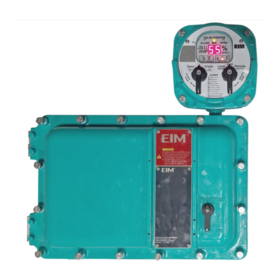
Section 2: Features Operation and Maintenance Manual July 2018 E2K-200-0718 Rev. 0 Section 2: Features The actuator features several assemblies as listed below – refer to Figure 1. • LDM – Local Display Module: Contains actuator micro-processor which monitor the system health and indicate the control feedback. •... - Page 7 Operation and Maintenance Manual Section 2: Features E2K-200-0718 Rev. 0 July 2018 Figure 2 Features...
-
Page 8: Section 3: Local Display Module
Section 3: Local Display Module Operation and Maintenance Manual July 2018 E2K-200-0718 Rev. 0 Section 3: Local Display Module Contains micro-processor controller. This is the main controller used to setup and operate the actuator. This module displays operating parameters, valve position, and alarms, and provides for configuration of the actuator controls. -
Page 9: Operational Display
Operation and Maintenance Manual Section 3: Local Display Module E2K-200-0718 Rev. 0 July 2018 3.0.3 Operational Display Valve position indication for Close / Mid Stroke / Open position is through use of long lasting LED’s. Percentage of Open or Close is shown on the digital readout during normal operation &... -
Page 10: Alarms Display
Section 3: Local Display Module Operation and Maintenance Manual July 2018 E2K-200-0718 Rev. 0 3.0.4 Alarms Display When an alarm occurs, it is automatically displayed by the two character LED display. The yellow MID LED will flash while any alarm is present. The display will alternate between the current position and the active alarm(s). -
Page 11: Section 4: Wiring
Operation and Maintenance Manual Section 4: Wiring E2K-200-0718 Rev. 0 July 2018 Section 4: Wiring Refer to wiring diagrams located at the back of this manual for wiring connections. Refer on Figure 1 for location of enclosures and conduit entries. Use conduit and seals in accordance with National Electric Code (NEC) and local codes. -
Page 12: Section 5: Limit Switch Settings
Section 5: Limit Switch Settings Operation and Maintenance Manual July 2018 E2K-200-0718 Rev. 0 Section 5: Limit Switch Settings Set Open and Close valve travel and torque limits in the AEE before operating valve in automatic mode. Travel and torque limits are set using a common screw driver. NOTE: If electrical operation is used to move the valve while setting limits, stop movement short of the desired position and use hand wheel to complete valve travel. - Page 13 Operation and Maintenance Manual Section 5: Limit Switch Settings E2K-200-0718 Rev. 0 July 2018 Place the screwdriver in the Close setting slot shown in Figure 5. Use the hand wheel to close the valve to the desired Close position. Note the rotation of the screwdriver while closing the valve.
- Page 14 Section 5: Limit Switch Settings Operation and Maintenance Manual July 2018 E2K-200-0718 Rev. 0 Insert the screwdriver in the Disengage Shaft slot as shown in Figure 6. Push the shaft down and rotate shaft 90 Figure 6 Use the screwdriver in the Close setting slot as shown in Figure 5. If the LSC switch rotor arrow does not line up vertically (within +15 ), rotate screwdriver in same direction noted in Step 2 until switch just rotates.
-
Page 15: Torque Seated Valves
Operation and Maintenance Manual Section 5: Limit Switch Settings E2K-200-0718 Rev. 0 July 2018 5.0.2 Torque Seated Valves If valve is torque seated and the geared limit contacts are used for indication only, the LSC (close limit) switch should be set several handwheel turns ahead of torque switch contact action. - Page 16 Section 5: Limit Switch Settings Operation and Maintenance Manual July 2018 E2K-200-0718 Rev. 0 To set Close Torque Switch (TSC) Close valve using hand wheel. Set valve to desired torque. Observe rotating dial for number that corresponds to desired Close Torque. Insert screwdriver in TSC slot.
-
Page 17: Section 6: Electronics Setup
Operation and Maintenance Manual Section 6: Electronics Setup E2K-200-0718 Rev. 0 July 2018 Section 6: Electronics Setup Use the Local Control (left) knob and Selector (right) knob to enter setup mode and to execute Setup functions. The table below outlines the knob functions for Setup mode. To access the electronics SETUP mode of operation, ensure the Selector Knob is placed in the OFF (Stop) position. -
Page 18: Alarm History Display
Section 6: Electronics Setup Operation and Maintenance Manual July 2018 E2K-200-0718 Rev. 0 When the actuator LDM is placed in SETUP mode of operation it first displays the Alarm History (AH) menu. The alarm history may be viewed without entering a passcode (See Alarm History Display section). -
Page 19: Setup Mode Display Sequence
Operation and Maintenance Manual Section 6: Electronics Setup E2K-200-0718 Rev. 0 July 2018 Setup Mode Display Sequence The three (3) amber LED’s for the LOR section flash to indicate Setup Mode. When in setup mode, the user must enter the REMOTE (NEXT) or LOCAL (BACK) within 120 seconds or the display will revert back to the normal display mode. - Page 20 Section 6: Electronics Setup Operation and Maintenance Manual July 2018 E2K-200-0718 Rev. 0 Table 3. Menu Parameter Value Units Default Display Alarm History? 0-1 0=No, Skip to 1st Passcode 1=Yes, Display History 1st older alarm Alarm None 2nd older alarm Alarm None 3rd older alarm...
-
Page 21: Analog Output Calibration
Operation and Maintenance Manual Section 6: Electronics Setup E2K-200-0718 Rev. 0 July 2018 Analog Output Calibration Analog position feedback is a loop powered 4-20mA output. Power must be supplied to the loop from an external loop supply. The 24VDC power available at terminals 6 and 7 of Connector P3-1 may be used to power the loop. -
Page 22: Emergency Shut Down (Esd) Setup
Section 6: Electronics Setup Operation and Maintenance Manual July 2018 E2K-200-0718 Rev. 0 6.4.1 Emergency Shut Down (ESD) Setup Local ESD is a hardware circuit within the Local Display Module that will detect an externally wired closed loop circuit connected to Terminals 5 and 7 of P3-1. When an open circuit is detected the local ESD is activated. - Page 23 Section 6: Electronics Setup Operation and Maintenance Manual E2K-200-0718 Rev. 0 July 2018 Figure 10 Wiring Diagram Electronics Setup...
- Page 24 Section 6: Electronics Setup Operation and Maintenance Manual July 2018 E2K-200-0718 Rev. 0 Figure 11 Typical User Wiring Diagram Electronics Setup...
- Page 26 The Emerson logo is a trademark and service mark of Emerson Electric Co. T +36 22 53 09 50 is a mark of one of the Emerson family of companies. All other marks are property of their respective owners. Strada Biffi 165 29017 Fiorenzuola d’Arda (PC)