
Related Manuals for Emerson EIM E796 M2CP


Summary of Contents for Emerson EIM E796 M2CP
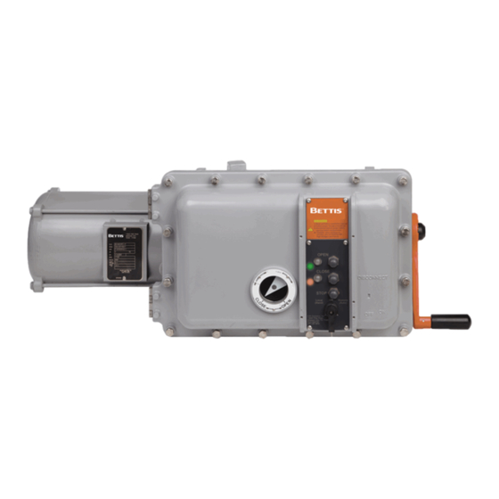
- Page 1 Installation and Maintenance Manual E2K-402-0817 Rev. 2 August 2017 EIM 2000 Series E796 M2CP...
-
Page 3: Table Of Contents
Installation and Maintenance Manual Table of Contents E2K-402-0817 Rev. 2 August 2017 Table of Contents Section 1: Introduction DO ........................ 1 DON'T ......................1 Lubrication ....................2 Maintenance ....................2 Pressure Relief ....................2 Short Term Storage ..................3 Long Term Storage ..................3 Section 2: M2CP Electical Hook Up Electrical Hook Up .................. -
Page 4: Section 1: Introduction
Section 1: Introduction Installation and Maintenance Manual August 2017 E2K-402-0817 Rev. 2 Section 1: Introduction DO follow proper storage procedures. Improper storage will voidwarranty. DANGER: DO check for proper motor rotation. If valve goes wrong direction when button is pushed, you have no torque or limit protection. 3-Phase incoming power voltage must have 2 wires reversed. -
Page 5: Lubrication
Installation and Maintenance Manual Section 1: Introduction E2K-402-0817 Rev. 2 August 2017 Lubrication EIM Actuators are factory filled with a high quality lubricant carefully selected to insure actuator performance under specified operating conditions. Refer to EIM JOB SPEC SHEET to identify the lubricant provided. Normal operation may not require lubricant replacement. -
Page 6: Short Term Storage
Section 1: Introduction Installation and Maintenance Manual August 2017 E2K-402-0817 Rev. 2 Short Term Storage (Stored at Job Site less than one year from shipment) Actuator should be stored with motor shaft in horizontal position and electrical enclosure in either the horizontal or vertical position. Figure 1 Cover Cover... -
Page 7: Section 2: M2Cp Electical Hook Up
Installation and Maintenance Manual Section 2: M2CP Electrical Hook Up E2K-402-0817 Rev. 2 August 2017 Section 2: M2CP Electical Hook Up Remove PWR and TBM covers to expose terminals for customer wiring. EIM Modular Modular Control Package (M2CP) is available configured in many combinations of electrical and electronic parts. -
Page 8: Electrical Hook Up
Section 2: M2CP Electrical Hook Up Installation and Maintenance Manual August 2017 E2K-402-0817 Rev. 2 Electrical Hook Up Step 1. Move valve to mid-position by handwheel. This will allow sufficient time to stop actuator in case of improper hook-up or reversed incoming power voltage phases. -
Page 9: Section 3: Assembly To Valves
Installation and Maintenance Manual Section 3: Assembly to Valves E2K-402-0817 Rev. 2 August 2017 Section 3: Assembly to Valves Threaded Valve Stem 3.1.1 Locknut Lockpin Installation Figure 3 ( 56) ( 55) (52) (54) With actuator in place on valve, ensure proper flange mating and valve actuator orientation. -
Page 10: Mounting Screws
Section 3: Assembly to Valves Installation and Maintenance Manual August 2017 E2K-402-0817 Rev. 2 Lower actuator over Stem onto valve flange. The screws thru valve flange into actuator must engage a minimum of one full screw diameter deep into bottom base and be tightened to a preload. -
Page 11: Spline Bushing (Quarter-Turn)
Installation and Maintenance Manual Section 3: Assembly to Valves E2K-402-0817 Rev. 2 August 2017 3.2.2 Spline Bushing (Quarter-Turn) EIM removable Spline Bushing allows easy adaptation to valve shaft diameter and Key. Actuator may be rotated with respect to valve shaft for unexpected or awkward field installations. - Page 12 Section 3: Assembly to Valves Installation and Maintenance Manual August 2017 E2K-402-0817 Rev. 2 Figure 5 Full MCP Frame Type M/MG (side mount) EIM Modular Control Package (MCP) is available configured in thousands of possible combinations of electrical and electronic parts. Refer to WIRING DIAGRAM and EIM JOB SPEC SHEET provided by EIM with each actuator.
-
Page 13: Section 4: Limit Switch Setting Instructions
Installation and Maintenance Manual Section 4: Limit Switch Setting Instructions E2K-402-0817 Rev. 2 August 2017 Section 4: Limit Switch Setting Instructions Before making limit switch setting Move valve to mid-position (use handwheel). Phase the power (motor) voltage and make sure that open contactor moves valve Open and close contactor moves valve Closed. - Page 14 Section 4: Limit Switch Setting Instructions Installation and Maintenance Manual August 2017 E2K-402-0817 Rev. 2 Disengage spring loaded gear: Push Disengage Shaft in (Fig. 7a) down, then rotate 90° so shaft is captured down. This will disengage limit switch gears from spring loaded drive gear.
-
Page 15: Set (Lsc) Close Limit Switch
Installation and Maintenance Manual Section 4: Limit Switch Setting Instructions E2K-402-0817 Rev. 2 August 2017 Line up LSO indicator: If switch rotor arrow does not line with round holes (within ± 15°) on plate as shown in Fig. 8a, rotate screwdriver in same direction noted in Step 1 until switch just rotates. -
Page 16: To Set Intermediate Switch (Lsa Or Lsb), If Included
Section 4: Limit Switch Setting Instructions Installation and Maintenance Manual August 2017 E2K-402-0817 Rev. 2 To set Intermediate Switch (LSA or LSB), if included Open Valve to desired position, then repeat steps 2 thru 5 of LSO. NOTE: “Jiggle” adjusting shafts. Torque Seated Valves If valve is a torque seated valve, and the geared limit contacts are used for indication only, the LSC switch should be set several handwheel turns ahead of torque switch contact... -
Page 17: To Set Open Torque Switch (Tso)
Installation and Maintenance Manual Section 4: Limit Switch Setting Instructions E2K-402-0817 Rev. 2 August 2017 DANGER: Reverse power voltage phasing removes torque switch protection from reversing contrac- tor coil circuits. Valve damage could occur. If phasing has not been checked, do so before proceeding. -
Page 18: Section 5: Multi-Turn Actuators
Section 5: Multi-turn Actuators Installation and Maintenance Manual August 2017 E2K-402-0817 Rev. 2 Section 5: Multi-turn Actuators Multi-turn top-mounted and side-mount bevel gear actuators require use of Gear Reduction Assembly part no. 84055-0000 for Mechanical Dial Position Indication MDPI and 1-turn Pot. -
Page 19: Quarter-Turn Model P, Q, R & M
Installation and Maintenance Manual Section 5: Multi-turn Actuators E2K-402-0817 Rev. 2 August 2017 Quarter-Turn Model P, Q, R & M Top-mount P, Q and R and several models of M/MG’s side-mount do not require MDPI gear reduction assembly for 1-turn Pot. If multi-turn Pot is required, EIM JOB SPEC SHEET will list 84131-0000 or the correct assembly. -
Page 20: Section 6: M2Cp Wiring Diagram Symbols
Section 6: M2CP Wiring Diagram Symbols Installation and Maintenance Manual August 2017 E2K-402-0817 Rev. 2 Section 6: M2CP Wiring Diagram Symbols Description Refer to EIM JOB SPEC SHEET and EIM WIRING DIAGRAM for components furnished. Figure 13 Potentiometer 1K Ohm CLOSE Potentiometer slider is geared to Valve Position and "in-step"... - Page 21 Installation and Maintenance Manual Section 6: M2CP Wiring Diagram Symbols E2K-402-0817 Rev. 2 August 2017 Figure 19 Pushbuttons N.C. STOP Momentary N.C. Contact Figure 20 Pushbuttons N.O. OPEN Momentary N.O. contacts connects control voltage to reversing contactor 8 coils. Seal-in contacts C and O (14,13) on contactor allow travel without continued holding down of pushbutton.
- Page 22 Section 6: M2CP Wiring Diagram Symbols Installation and Maintenance Manual August 2017 E2K-402-0817 Rev. 2 Figure 25 Reversing Contactor Showing Open and Close coils, Mechanical Interlock, and Electrical Interlock Contacts O (21, 22) & C (21, 22) Figure 26 Nuisance Trip To prevent (TSO) contact tripping when valve has been jammed closed - LSC contact allows valve to open slightly.
- Page 23 Installation and Maintenance Manual Section 6: M2CP Wiring Diagram Symbols E2K-402-0817 Rev. 2 August 2017 Figure 29 3 Phase Motor with overload relay heaters & contractor contacts MOTOR Thermal Protector Figure 30 SS Table S1 X O O S2 O O X S3 O X X S4 X X O S5 X O O...
-
Page 24: Section 7: Troubleshooting
Section 7: Troubleshooting Installation and Maintenance Manual August 2017 E2K-402-0817 Rev. 2 Section 7: Troubleshooting Symptom Probable Cause Corrective Action Check Fuse and Replace Blown Control Fuse as necessary Refer to appropriate wiring Motor will not Run Open in Control Circuit diagram and check for continuity Insulation Resistance... - Page 25 Installation and Maintenance Manual Section 7: Troubleshooting E2K-402-0817 Rev. 2 August 2017 Motor Bearing Assembly Repair or replace as necessary Malfunction Sheared gear key Replace (fastener pin) Motor runs but will not Stripped Gearing Replace operate the valve Broken Valve Stem or Repair or replace as necessary Stripped Stem Nut PS shifter position or...
- Page 27 ©2017 Emerson. All rights reserved. No. 1 Lai Yuan Road EUROPE Wuqing Development Area The Emerson logo is a trademark and service mark of Emerson Electric Co. Tianjin 301700 Berenyi u. 72- 100 is a mark of one of the Emerson family of companies.