
Related Manuals for Emerson EIM HQ Series


Summary of Contents for Emerson EIM HQ Series
- Page 1 Installation, Operation and Maintenance Manual VCIOM-15257-EN Rev. 1 May 2020 EIM HQ Series Quarter-Turn Electric Actuator Models HQ-006 / Manual HQ-402-0606...
- Page 2 Notes Installation, Operation and Maintenance Manual May 2020 VCIOM-15257-EN Rev. 1 This page intentionally left blank...
-
Page 3: Table Of Contents
Installation, Operation and Maintenance Manual Table of Contents VCIOM-15257-EN Rev. 1 May 2020 Table of Contents Section 1: General Generalities ......................1 Section 2: Actuator Mounting Actuator Mounting ....................2 Section 3: External Construction External Construction ..................... 3 Section 4: Standard Wiring Diagram Standard Wiring Diagram .................. -
Page 4: Section 1: General
Section 1: General Installation, Operation and Maintenance Manual May 2020 VCIOM-15257-EN Rev. 1 Section 1: General HQ series electric actuators are design to provide reliable and efficient operation of 90° quarter-turn valves, dampers, etc. WARNING Use caution when working in, with, or around valves and actuators. High pressures, forces, voltages and flammable media can be present. -
Page 5: Section 2: Actuator Mounting
Installation, Operation and Maintenance Manual Section 2: Actuator Mounting VCIOM-15257-EN Rev. 1 May 2020 Section 2: Actuator Mounting The actuator may be mounted in any position. The HQ-006 actuator is supplied with a female output drive and adaptor bushings. ISO5211 FO3/FO5 and FO7 Bolt patterns are provided for actuator mounting. -
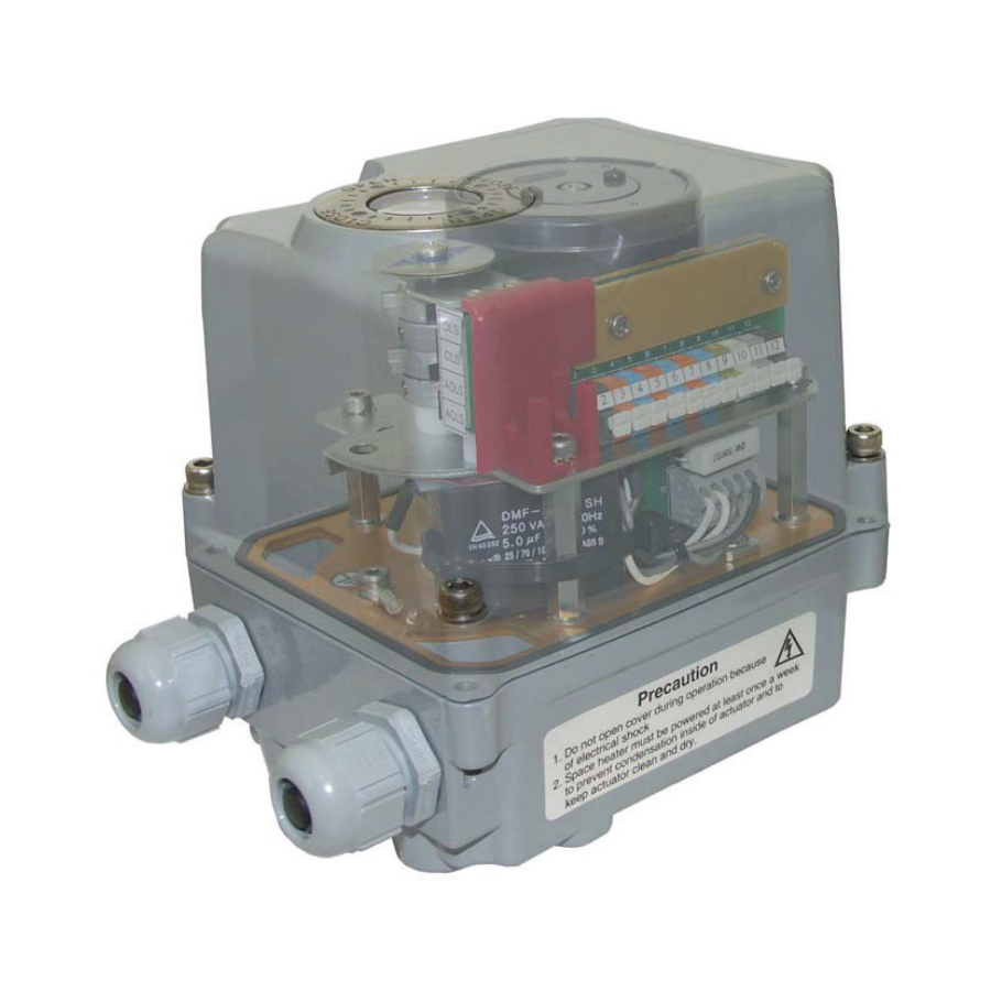
Page 6: Section 3: External Construction
Section 3: External Construction Installation, Operation and Maintenance Manual May 2020 VCIOM-15257-EN Rev. 1 Section 3: External Construction Figure 2 CABLE ENTRY 2 Plcs PG 0.531" (13.5) (1/4" - 1/2" Wire Cable) External Construction... -
Page 7: Section 4: Standard Wiring Diagram
Installation, Operation and Maintenance Manual Section 4: Standard Wiring Diagram VCIOM-15257-EN Rev. 1 May 2020 Section 4: Standard Wiring Diagram Figure 3 INCOMING POWER 1 PH (110 OR 220 V A C) AUX. CONTACT 2 EXTRA SWITCHES MAX. 250 V AC 3 A CLOSE OPEN CLOSE... -
Page 8: Section 5: Manual Override
Section 5: Manual Override Installation, Operation and Maintenance Manual May 2020 VCIOM-15257-EN Rev. 1 Section 5: Manual Override The HQ-006 actuator comes standard with a manual override nut. This is located on the bottom of the unit, and can be easily operated with a 5M wrench. Figure 4 Manual Override... -
Page 9: Section 6: Electrical Connection
Installation, Operation and Maintenance Manual Section 6: Electrica l Connection VCIOM-15257-EN Rev. 1 May 2020 Section 6: Electrical Connection • Move valve to mid-position by override nut. This will allow sufficient time to stop actuator in case of improper hook-up. •... -
Page 10: Section 7: Limit Switch Setting Instructions
Section 7: Limit Switch Setting Instructions Installation, Operation and Maintenance Manual May 2020 VCIOM-15257-EN Rev. 1 Section 7: Limit Switch Setting Instructions • Operate the actuator manually to closed position • Using a hex wrench, loosen the cam adjustment screw in the CLS limit switch cam •... -
Page 11: Section 8: Lubrication
Installation, Operation and Maintenance Manual Section 8: Lubrication VCIOM-15257-EN Rev. 1 May 2020 Section 8: Lubrication The HQ series actuators are totally enclosed units with a permanently lubricated gear trains (Moly EP Grease). Once installed lubrication should not be required. However, periodic preventative maintenance will extend the operating life of the actuator. -
Page 12: Section 9: Mdpi Settings
Section 9: MDPI Settings Installation, Operation and Maintenance Manual May 2020 VCIOM-15257-EN Rev. 1 Section 9: MDPI Settings • Manually rotate actuator to fully closed position • Remove actuator cover • Loosen indicator screw • Adjust indicator to correct orientation •... -
Page 13: Section 10: Maintenance And Storage
VCIOM-15257-EN Rev. 1 May 2020 Section 10: Maintenance and Storage At least once a year a check should be made of your EIM HQ Series Actuator. • Disconnect all power to actuator. • Open electrical enclosure. Inspect and tighten all electrical connections. -
Page 14: Section 11: Troubleshooting
Section 11: Troubleshooting Installation, Operation and Maintenance Manual May 2020 VCIOM-15257-EN Rev. 1 Section 11: Troubleshooting The following instructions are offered for the most common difficulties encounter during installation and start-up. Table 1. SYMPTOM PROBABLE CAUSE CORRECTIVE ACTION Refer to appropriate wiring diagram Open in control circuit and check for continuity Motor will not run... -
Page 15: Section 12: Product Features And Specifications
Installation, Operation and Maintenance Manual Section 12: Product Features and Specifications VCIOM-15257-EN Rev. 1 May 2020 Section 12: Product Features and Specifications Enclosure Rated Weatherproof IP67 Enclosure High grade aluminium alloy, corrosion coated Power Supply 110/220 V AC, 1 PH, 50/60 Hz Motor Reversible Motor Limit Switches... - Page 16 Székesfehérvár 8000 T +86 22 8212 3300 Hungary The Emerson logo is a trademark and service mark of Emerson Electric Co. T +36 22 53 09 50 is a mark of one of the Emerson family of companies. All other marks are property of their respective owners.