Kenwood NX-200 Service Manual
Vhf digital transceiver
Hide thumbs
Also See for NX-200:
- Function reference (608 pages) ,
- Service manual (172 pages) ,
- Instruction manual (136 pages)
Table of Contents
Advertisement
Quick Links
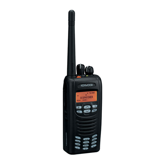
VHF DIGITAL TRANSCEIVER
NX-200(G)
SERVICE MANUAL
NX-200(G) K
Knob (Selector)
(K29-9408-13)
Knob (Volume)
(K29-9407-03)
Badge
(B43-1606-14)
Knob (PTT)
(K29-9405-03)
Packing (6 key)
(G53-1765-11)
Plastic cabinet assy
(6 key)
(A02-4002-23)
GENERAL .................................................................. 2
SYSTEM SET-UP ....................................................... 3
REALIGNMENT ......................................................... 3
INSTALLATION .......................................................... 6
DISASSEMBLY FOR REPAIR ................................... 8
CIRCUIT DESCRIPTION ......................................... 13
COMPONENTS DESCRIPTION .............................. 19
PARTS LIST ............................................................. 21
EXPLODED VIEW .................................................... 32
PACKING ................................................................. 33
TROUBLE SHOOTING ............................................ 34
ADJUSTMENT ......................................................... 39
TERMINAL FUNCTION ........................................... 61
This product complies with the RoHs directive for the European market.
NX-200(G) K2
Helical Antenna
(KRA-43G: option)
CONTENTS
PC BOARD
SUB (GPS) UNIT (X58-5240-10) ........................ 69
CONTROL UNIT (X53-4590-XX) ........................ 70
TX-RX UNIT (X57-8950-12) ................................ 74
INTERCONNECTION DIAGRAM ............................. 78
SCHEMATIC DIAGRAM .......................................... 80
BLOCK DIAGRAM .................................................. 94
LEVEL DIAGRAM ................................................... 98
KNB-47L (Li-ion Battery Pack) ......................... 99
KNB-48L (Li-ion Battery Pack) ......................... 99
KRA-43G (VHF,GPS Helical Antenna) .............. 99
SPECIFICATIONS ................................ BACK COVER
© 2014-01 PRINTED IN JA PAN
RQ018 ( K ) B5B-7111-00
Knob (Selector)
(K29-9408-13)
Knob (Volume)
(K29-9407-03)
Badge
(B43-1606-14)
Knob (PTT)
(K29-9405-03)
Packing (18 key)
(G53-1766-11)
Plastic cabinet assy
(18 key)
(A02-4003-23)
This product uses Lead Free solder.
Advertisement
Table of Contents

Related Manuals for Kenwood NX-200


Summary of Contents for Kenwood NX-200
-
Page 1: Table Of Contents
VHF DIGITAL TRANSCEIVER NX-200(G) SERVICE MANUAL © 2014-01 PRINTED IN JA PAN RQ018 ( K ) B5B-7111-00 NX-200(G) K NX-200(G) K2 Helical Antenna (KRA-43G: option) Knob (Selector) Knob (Selector) (K29-9408-13) (K29-9408-13) Knob (Volume) Knob (Volume) (K29-9407-03) (K29-9407-03) Badge Badge (B43-1606-14) -
Page 2: General
Disclaimer KENWOOD product memories. While every precaution has been taken in the preparation of this manual, JVC KENWOOD Corporation assumes no NXDN Transceivers: responsibility for errors or omissions. Neither is any liability The AMBE+2(TM) voice coding technology is embedded assumed for damages resulting from the use of the informa- in the fi... -
Page 3: System Set-Up
NX-200(G) SYSTEM SET-UP Merchandise received Frequency range (MHz) RF power Type DTMF keypad TX/RX 136~174 NX-200(G) K Choose the type of transceiver TX/RX 136~174 NX-200(G) K2 A personal computer, programming interface (KPG-36A/36U), and programming software (KPG-111D) Transceiver programming are required for programming. - Page 4 NX-200(G) REALIGNMENT 5-2. Connection procedure 2. How to Enter Each Mode 1. Connect the transceiver to the computer using the inter- Mode Operation face cable (KPG-36A/36U). (Conection is the same as in User mode Power ON the PC Mode.) Panel test mode...
- Page 5 NX-200(G) REALIGNMENT 6-2. Connection procedure 7. Clone Mode Connect the transceiver to the personal computer using Programming data can be transferred from one transceiv- the interface cable (KPG-36A/36U). (Connection is the same er to another by connecting them via their external universal as in the PC Mode.)
-
Page 6: Installation
NX-200(G) REALIGNMENT 4. Power ON the target transceiver. 5. Connect the cloning cable (part No. E30-3325-05) to the Cloning cable (E30-3325-05) universal connectors on the source and target. 6. Press the [ ] key on the source while the source displays “CLONE MODE”. - Page 7 NX-200(G) INSTALLATION 3. Remove the coaxial cable from the GPS PCB. 6. Fold the fi brous sheet (G11-1362-04) in half, and cover Note: When you remove the coaxial cable from the GPS the terminal of the coaxial cable as shown in the fi gure.
-
Page 8: Disassembly For Repair
NX-200(G) INSTALLATION Voice Guide & Storage Unit (VGS-1: Option) ■ Installing the VGS-1 VGS-1 . Attach the flat spring (G02-1846-03) to the VGS-1 as shown in the fi gure. Note: PCB hollow Attach the fl at spring so that its convex fi ts the PCB hol- Flat spring low of the VGS-1. - Page 9 NX-200(G) DISASSEMBLY FOR REPAIR 2. Precautions for Disassembly ■ Removing the TX-RX unit from the chassis 1. Remove the cord ASSY from the connector of the TX-RX unit (CN400) a . 2. Remove the PTT FPC from the connector of the TX-RX unit (CN401) b .
- Page 10 NX-200(G) DISASSEMBLY FOR REPAIR ■ Removing the lithium cell (W09-0971-05) ■ Inserting the Volume and Channel switch into Insert a non-conductive screwdriver to groove of one side the chassis of the socket (CN401,CN11) and pry the lithium cell up Insert the volume and channel switch into the chassis from the socket.
- Page 11 NX-200(G) DISASSEMBLY FOR REPAIR ■ Relay hardware (E29-1242-04) installation procedure ■ Forming the GPS coaxial cable(E37-1716-05) 1. Fit one side of the relay hardware to a right corner of the Form the GPS coaxial cable as shown in the fi gure.
- Page 12 Part Number Remark Sticker B42-7417-04 “NEXEDGE” is printed. Plastic Cabinet (6-key) A02-4002-23 Badge B43-1606-04 “KENWOOD” is printed. Plastic Cabinet (18-key) A02-4003-23 Fibrous Sheet (SP) G10-1373-04 Used for fi xing the LCD ASSY on the Illumination Guide (LCD). LCD ASSY B38-0923-05...
-
Page 13: Circuit Description
CIRCUIT DESCRIPTION 1. Overview 2. Frequency Confi guration The NX-200(G) is a VHF portable transceiver designed The receiver is a double-conversion superheterodyne us- to operate in the frequency range of 136 to 174MHz. The ing the fi rst intermediate frequency (IF) of 58.05MHz and the unit consists of receiver, transmitter, phase-locked loop (PLL) second IF of 450kHz. - Page 14 NX-200(G) CIRCUIT DESCRIPTION 3-3. Audio Amplifi er Circuit 3-4. Squelch Circuit Audio processing (high-pass filter, low-pass filter, de- It amplifies the demodulated noise signal from IC108 emphasized and so on) at FM mode and decoding at NXDN after fi ltering through the BPF circuit. Then, the amplifi ed sig- mode are processed by DSP.
- Page 15 NX-200(G) CIRCUIT DESCRIPTION 4-3. VOX 4-5. APC Circuit IC716 (2/2) amplifi es the audio signal captured in the mi- The APC circuit always monitors the current flow- crophone. The signal is then converted into the DC voltage, ing through the Final power amplifier (Q106) and keeps rectifi...
- Page 16 NX-200(G) CIRCUIT DESCRIPTION 5-3. PLL IC (IC3) 5-4. Doubler (Q4) The PLL IC compares the differences in phases of the The doubler (Q4) extracts the twice harmonic component VCO oscillation frequency and the VCTCXO reference from the signal from the VCO. This twice harmonic compo- frequency, returns the difference to the VCO CV terminal nents is then fed into PLL (IC3) through band pass fi...
- Page 17 NX-200(G) CIRCUIT DESCRIPTION 6-2. Memory Circuit 6-6. DSP The memory circuit consists of the ASIC (IC108) and the The DSP circuit consists of a DSP (IC102) and process- SRAM (IC103) and fl ash memory (IC101). The fl ash memory es the base band signal. The DSP operates on an external has capacity of 32M-bit that contains the transceiver control clock of 18.432MHz (the same as the IC108), the I/O section...
- Page 18 NX-200(G) CIRCUIT DESCRIPTION 8. Signaling Circuit TX-RX unit (X57) F400 RF Final AMP 8-1. Encode (QT/DQT/LTR/DTMF/2-tone/MSK) 2.5A Each signaling data signal of QT, DQT, LTR, DTMF, IC400 /SAVE 2-tone and MSK is generated by the DSP circuit, super- Q405 posed on a modulation signal and output from IC108. The...
-
Page 19: Components Description
NX-200(G) COMPONENTS DESCRIPTION Control unit (X53-4590-XX) Ref. No. Part Name Description Ref. No. Part Name Description Q103 12key backlight switch LCD contrast Q401,402 Level converter IC101 FLASH ROM Q403 Transistor SB2 switch IC102 Q404 SB2 switch control IC103 SRAM Q405... - Page 20 NX-200(G) COMPONENTS DESCRIPTION TX-RX unit (X57-8950-12) Ref. No. Part Name Description Ref. No. Part Name Description Diode Ripple fi lter Temperature sensor D2,3 Diode f-in RF switch AF AMP for VCO tune Diode Bypass diode PLL IC D5,6 Diode f-in RF switch...
-
Page 21: Parts List
Les articles non mentionnes dans le Parts No. ne sont pas fournis. C : China X : Australia M : Oth er Areas Teile ohne Parts No. werden nicht geliefert. NX-200 (G) CONTROL UNIT (X53-4590-XX) Desti- Desti- Ref. No. Ad dress Parts No. - Page 22 NX-200(G) PARTS LIST CONTROL UNIT (X53-4590-XX) Desti- Desti- Ref No. Ad dress Parts No. Description Ref No. Ad dress Parts No. Description nation nation CC73HCH1H221J CHIP C 220PF C443 CK73HB1E103K CHIP C 0.010UF K CC73HCH1H101J CHIP C 100PF C445 CK73HB1H102K...
- Page 23 NX-200(G) PARTS LIST CONTROL UNIT (X53-4590-XX) Desti- Desti- Ref No. Ad dress Parts No. Description Ref No. Ad dress Parts No. Description nation nation C759,760 CK73HB1E103K CHIP C 0.010UF K L702 L92-0162-05 BEADS CORE C761 CC73HCH1H100D CHIP C 10PF L704-709...
- Page 24 NX-200(G) PARTS LIST CONTROL UNIT (X53-4590-XX) Desti- Desti- Ref No. Ad dress Parts No. Description Ref No. Ad dress Parts No. Description nation nation R145-147 RK73HB1J104J CHIP R 100K 1/16W R448 RK73HB1J103J CHIP R 1/16W R449-452 RK73HB1J474J CHIP R 470K J...
- Page 25 NX-200(G) PARTS LIST CONTROL UNIT (X53-4590-XX) Desti- Desti- Ref No. Ad dress Parts No. Description Ref No. Ad dress Parts No. Description nation nation R725 RK73HB1J100J CHIP R 1/16W R803 RK73HB1J103J CHIP R 1/16W R726 RK73HB1J104J CHIP R 100K J...
- Page 26 NX-200(G) PARTS LIST CONTROL UNIT (X53-4590-XX) TX-RX UNIT (X57-8950-12) Desti- Desti- Ref No. Ad dress Parts No. Description Ref No. Ad dress Parts No. Description nation nation D409,410 DA2S101 DIODE Q403 2SJ648-A D411 KDR720F-P DIODE Q404 SSM3K15TE(F) D412 KDS121-P DIODE...
- Page 27 NX-200(G) PARTS LIST TX-RX UNIT (X57-8950-12) Desti- Desti- Ref No. Ad dress Parts No. Description Ref No. Ad dress Parts No. Description nation nation C45-47 CK73HB1H471K CHIP C 470PF C139 CK73HB1H471K CHIP C 470PF C93-1906-05 CHIP TNTL 0.047UF 35WV C140...
- Page 28 NX-200(G) PARTS LIST TX-RX UNIT (X57-8950-12) Desti- Desti- Ref No. Ad dress Parts No. Description Ref No. Ad dress Parts No. Description nation nation C236,237 CK73FB1A106K CHIP C 10UF C416 CK73GB1E105K CHIP C 1.0UF C238 CK73HB1C103K CHIP C 0.010UF K...
- Page 29 NX-200(G) PARTS LIST TX-RX UNIT (X57-8950-12) Desti- Desti- Ref No. Ad dress Parts No. Description Ref No. Ad dress Parts No. Description nation nation L104 L92-0138-05 CHIP FERRITE RK73HB1J223J CHIP R 1/16W L105 L40-4775-92 SMALL FIXED INDUCTOR (47NH) RK73HB1J000J CHIP R...
- Page 30 NX-200(G) PARTS LIST TX-RX UNIT (X57-8950-12) Desti- Desti- Ref No. Ad dress Parts No. Description Ref No. Ad dress Parts No. Description nation nation R133 RK73HB1J331J CHIP R 1/16W R245 RK73HB1J104J CHIP R 100K J 1/16W R134 RK73HB1J561J CHIP R...
- Page 31 NX-200(G) PARTS LIST TX-RX UNIT (X57-7360-10) Desti- Desti- Ref No. Ad dress Parts No. Description Ref No. Ad dress Parts No. Description nation nation EM6M2 R440 RK73HB1J473J CHIP R 1/16W R452 RK73HB1J102J CHIP R 1.0K 1/16W 2SK508NV (K52) 2SJ347F R453...
-
Page 32: Exploded View
NX-200(G) EXPLODED VIEW Control unit (X53) Sub (GPS) unit (X58) Hx10 TX-RX unit (X57 A/2) : N08-0564-04 : N09-2426-14 C M2.6 x 8 : N09-2440-15 : N09-6549-04 E M2.6 x 4 : N09-6554-05 : N14-0844-04 2 x 5 : N83-2005-48 Parts with the exploded numbers larger than 700 are not supplied. -
Page 33: Packing
NX-200(G) PACKING 60 Belt clip (B09-0712-03) (J29-0730-05) 53 Packing (Cap) (G53-1769-04) G Pan head machine screw (N09-6585-19)x2 A Dressed screw (N08-0564-04) 94 Packing fixture (H12-4293-02) 95 Cartion board (H13-2135-04) 14 Instruction manual (B62-2014-10) 96 Item cartion case (H52-2839-02) Parts with the exploded numbers larger than 700 are not supplied. -
Page 34: Trouble Shooting
NX-200(G) TROUBLE SHOOTING Fault Diagnosis of the BGA (Ball Grid Array) IC ■ Overview A fl owchart for determining whether or not the transceiver can be powered on (the LCD does not function even if the power switch is turned on) due to broken BGA parts. - Page 35 NX-200(G) TROUBLE SHOOTING When a normal ● Checking the output signal value is confirmed. from the ASIC When an abnormal value is confirmed. Points to be checked Normal voltage Remove R432. If the ASIC side is 0V, SBC R432 3.3V the ASIC/FLASH/SRAM may be broken.
- Page 36 NX-200(G) TROUBLE SHOOTING Failure Diagnosis of the GPS section ■ Overview When the GPS function does not operate, use this fl ow chart to determine the problem. ■ Major parts for a GPS circuit (TX-RX unit and Sub (GPS) unit) •...
- Page 37 NX-200(G) TROUBLE SHOOTING When a normal condition is confirmed. When an abnormal When an abnormal condition is confirmed. condition is confirmed. Verify the GPS data (TXD). [The TXD1 line circuit is faulty] Verify the state of the TXD1 line. R10: High (3.3V) Replace any abnormal parts.
- Page 38 Various Adjustment Data General adjustment values for the (PC Test mode) X53-459 (NX-200G). Model name: [X53-459] NX-200/300S1 (No DTMF keypad) or NX-200/300S2 (with DTMF Kenwood ESN keypad) Type: K The same number as the Kenwood ESN label is written. The shielding plate is soldered...
-
Page 39: Adjustment
If changing to the original Kenwood ESN and NXDN ESN, please contact our service center. Note: A UPC code and UPC barcode is not printed on the Kenwood ESN Label. If necessary, cut the label at the cut-off line and attach only the serial number. ADJUSTMENT... - Page 40 NX-200(G) ADJUSTMENT ■ Key operation • LED indicator Red LED Lights during transmission. “FNC” not appears on the sub LCD display Green LED Lights when there is carrier. Function Display • Sub LCD indicator [Selector] - “FNC” Appears at function on.
- Page 41 NX-200(G) ADJUSTMENT • Analog mode signaling • LCD display in panel tuning mode CV voltage, AD value, etc None None Sub LCD display None 100Hz Square Wave CNTR Main LCD display LTR Data: LTR Data: AREA=0, GOTO=12 AREA=0, GOTO=12 HOME=12...
- Page 42 NX-200(G) ADJUSTMENT ■ Adjustment item supplement Adjustment Item Description LCD contrast The contrast of LCD display can be changed. “Counterclockwise Volume” is adjusted at the minimum volume position. Counterclockwise Volume “Clockwise Volume” is adjusted at the maximum volume position. These adjustments can correct the volume variation.
- Page 43 NX-200(G) ADJUSTMENT ■ Adjustment item and Display Aw (Analog An (Analog Nn (NXDN Nar- Nv (NXDN Very Adjusutment Main LCD Adjust item Wide) Narrow) row) Narrow) Order Sub LCD display item display Number Adjustment range 1 point ADJ Common LCD contrast...
- Page 44 NX-200(G) ADJUSTMENT Aw (Analog An (Analog Nn (NXDN Nar- Nv (NXDN Very Adjusutment Main LCD Adjust item Wide) Narrow) row) Narrow) Order Sub LCD display item display Number Adjustment range (RSSI measurement Receive Sensitivity 2 SENS2 value) Section 3 1~256...
- Page 45 NX-200(G) ADJUSTMENT [Side2] Analog MAX Deviation Analog MAX Deviation Narrow Wide ADEV ADEV ] press ] hold 5 reference level Adjustments [Side2] QT Deviation QT Deviation Narrow Wide ] press ] hold [Side2] DQT Deviation DQT Deviation Narrow Wide ] press...
- Page 46 In order to turn the volume nut and the channel selector Ω Li-ion Normal Capacity Battery: R1=560k nut, use a recommendation tool. KENWOOD part No.: W05-1123-00 Schematic diagram ■ Battery jig (W05-1370-00) –Terminal Connect the power cable properly between the battery...
- Page 47 NX-200(G) ADJUSTMENT ■ Universal connector BLU (7) To transceiver PTT SW Use the interface cable (KPG-36A/36U) for PC tuning or the lead wire with plug (E30-3287-28) and screw (N08-0535- BRN (10) 08) for panel tuning. Connect the plug to the universal con- nector of the transceiver and tighten the screw.
- Page 48 NX-200(G) ADJUSTMENT Radio Check Section Condition Measurement Adjustment Specifi cations / Item Test- Remarks Panel test mode PC test mode Unit Terminal Unit Parts Method equipment 1. Frequency 1) CH-Sig: 1-1 1) Test Channel f. counter Panel ANT Check an internal ±0.5ppm...
- Page 49 NX-200(G) ADJUSTMENT Condition Measurement Adjustment Specifi cations / Item Test- Remarks Panel test mode PC test mode Unit Terminal Unit Parts Method equipment 5. Sensitivity 1) CH-Sig: 1-1 1) Test Channel Check 12dB SINAD or check SSG output Channel: 1...
- Page 50 NX-200(G) ADJUSTMENT Condition Measurement Adjustment Specifi cations / Item Test- Remarks Panel tuning mode PC test mode Unit Terminal Unit Parts Method equipment 5. Receive 1) Adj item: [RAST] 1) Adj item: Panel [Panel The sub LCD 2.5V±0.1V Assist Adjust: []٭٭٭...
- Page 51 NX-200(G) ADJUSTMENT Transmitter Section Condition Measurement Adjustment Specifi cations / Item Test- Remarks Panel tuning mode PC test mode Unit Terminal Unit Parts Method equipment 1. High 1) Adj item: [HIPWR] 1) Adj item: [High Power meter Panel ANT Panel [Panel 5.0W...
- Page 52 NX-200(G) ADJUSTMENT Condition Measurement Adjustment Specifi cations / Item Test- Remarks Panel tuning mode PC test mode Unit Terminal Unit Parts Method equipment Maximum 1) Adj item: [Nv NDEV] 1) Adj item: [Maximum Deviation Panel ANT Panel [Panel 1337Hz 1311~1363Hz Deviation Adjust: []٭٭٭٭...
- Page 53 NX-200(G) ADJUSTMENT Condition Measurement Adjustment Specifi cations / Item Test- Remarks Panel tuning mode PC test mode Unit Terminal Unit Parts Method equipment 1) Adj item: [Aw QT] 1) Adj item: [QT Devia- Deviation Panel ANT Panel [Panel Write the value as 0.75kHz±0.05kHz...
- Page 54 NX-200(G) ADJUSTMENT Condition Measurement Adjustment Specifi cations / Item Test- Remarks Panel tuning mode PC test mode Unit Terminal Unit Parts Method equipment 10. Single 1) Adj item: [An TONE] 1) Adj item: [Single Deviation Panel ANT Panel [Panel Write the value as 1.50kHz±0.05kHz...
- Page 55 NX-200(G) ADJUSTMENT Condition Measurement Adjustment Specifi cations / Item Test- Remarks Panel tuning mode PC test mode Unit Terminal Unit Parts Method equipment 15. BATT 1) Adj item: [BATT] 1) Adj item:[Battery Power meter Panel ANT Press the PTT detection Adjust: []٭٭٭...
- Page 56 NX-200(G) ADJUSTMENT Necessary adjustment and order Mode Signaling Wide Narrow Very Narrow Step1. Balance adjust Step1. Balance adjust Audio Step2. Maximum Deviation (NXDN Narrow) Step2. Maximum Deviation (NXDN Very Narrow) NXDN Step1. Balance adjust CWID Step2. Maximum Deviation (Analog Narrow) Step3.
- Page 57 NX-200(G) ADJUSTMENT Condition Measurement Adjustment Specifi cations / Item Test- Remarks Panel tuning mode PC test mode Unit Terminal Unit Parts Method equipment 3. Sensitivity 2 1) Adj item: [SENS2] 1) Adj item: Panel ANT Panel [Panel Write the value as followings.
- Page 58 NX-200(G) ADJUSTMENT Condition Measurement Adjustment Specifi cations / Item Test- Remarks Panel tuning mode PC test mode Unit Terminal Unit Parts Method equipment 5. Open 1) Adj item: [An SQL] 1) Adj item: Panel ANT [Panel tuning mode] “Open Squelch”...
- Page 59 NX-200(G) ADJUSTMENT Condition Measurement Adjustment Specifi cations / Item Test- Remarks Panel tuning mode PC test mode Unit Terminal Unit Parts Method equipment Low RSSI 1) Adj item: [Aw LRSSI] 1) Adj item: [Low RSSI Panel ANT [Panel tuning mode] at 118dBm Adjust: []٭٭٭...
- Page 60 NX-200(G) ADJUSTMENT Condition Measurement Adjustment Specifi cations / Item Test- Remarks Panel tuning mode PC test mode Unit Terminal Unit Parts Method equipment High RSSI 1) Adj item: [Nv 1) Adj item: [High Panel ANT [Panel tuning mode] Adjust with the at –80dBm...
-
Page 61: Terminal Function
NX-200(G) TERMINAL FUNCTION Control unit (X53-4590-XX) Pin No. Name Function Pin No. Name Function Power output after passing through the fuse Chip select output Power input after power switch /RES LCD reset output CN404 Address bus 0 output LED_G Green LED control output... - Page 62 NX-200(G) TERMINAL FUNCTION Pin No. Name Function Pin No. Name Function Thermistor voltage input OPT2 PLL lock detect input 38M output RXEO Refer to “CN710 26-pin connector SCK1 PLL clock output RXEI specifi cation” described on pages 62 to 64.
- Page 63 NX-200(G) TERMINAL FUNCTION SUB (GPS) unit (X58-5240-10) Pin No. Name Function Side_G Key matrix input (SIDE1,2 key) Pin No. Name Function Side_1 Key matrix output (SIDE1 key) CN10 W_/N No connection No connection SDO1 PLL serial data input UART data output...
- Page 64 NX-200(G) TERMINAL FUNCTION Universal connector Rating and Condition Signal Pin No. Name I/O Function Type Parameter Unit EXT/INT speaker switch input Digital L: External speaker ON H: Internal speaker ON [8Ω load] Max output power (1kHz, Batt=7.5V) Analog BTL output + for external speaker [8Ω...
- Page 65 NX-200(G) TERMINAL FUNCTION CN710 26-pin connector specifi cation Rating and Condition Pin No. Name Signal Type Parameter Unit OPT1 [Input] VIH OPT4 [Input] VIL OPT5 Digital [Output] VOH OPT8 [Output] VOL OPT11 OPT3 [Input] VIH OPT7 [Input] VIL Digital OPT2...
- Page 66 NX-200(G) TERMINAL FUNCTION Rating and Condition Pin No. Name Signal Type Parameter Unit Output Amplitude (1kHz, 60% deviation) mVp-p Coupling Capacitor µF RXEO Analog Ω Output Impedance 2.2k Allowable Frequency 3000 Input Amplitude (1kHz, 60% deviation) mVp-p Coupling Capacitor µF...
- Page 67 NX-200(G) TERMINAL FUNCTION Pin No. Name Device Connection Function ANI board 26P_RD VGS-1 Serial data input Scrambler board Serial data input ANI board 26P_TD VGS-1 Serial data output Scrambler board Serial data output ANI board PTT signal output VGS-1 Enable...
- Page 68 NX-200(G) TERMINAL FUNCTION Pin No. Name Device Connection Function ANI board Man-Down Man-Down output VGS-1 User programmable port OPT11 None: Hi-Z with Pull up Scrambler board [COR] L: Detect carrier [TOR] L: Detect signaling [LOK](Conventional) L: Transmitting [LOK](LTR) L: Link...
-
Page 69: Sub (Gps) Unit (X58-5240-10)
NX-200(G) PC BOARD SUB (GPS) UNIT (X58-5240-10) Component side view (J79-0432-09) J79-0432-09 SUB (GPS) UNIT (X58-5240-10) Foil side view (J79-0432-09) J79-0432-09 CN10 CN11 BATTER +SIDE UP OPT5 Ref. No. Address Ref. No. Address... -
Page 70: Control Unit (X53-4590-Xx)
NX-200(G) NX-200(G) PC BOARD ADJUSTMENT CONTROL UNIT (X53-4590-XX) -10: K -11: K2 Component side view (J79-0131-39) J79-0131-39 Ref. No. Address Ref. No. Address Ref. No. Address IC415... - Page 71 NX-200(G) PC BOARD CONTROL UNIT (X53-4590-XX) -10: K -11: K2 Component side view (J79-0131-39) CN22 CN23 /RES R406 C452 R500 CN24 Component side Layer 1 Layer 2 Layer 3 Layer 4 Layer 5 Layer 6 Foil side...
- Page 72 NX-200(G) NX-200(G) PC BOARD ADJUSTMENT CONTROL UNIT (X53-4590-XX) -10: K -11: K2 Foil side view (J79-0131-39) R402 D409 L719 R472 R496 C429 R442 Q405 L410 R474 C440 IC413 C415 + L401 R462 R133 R489 C437 C416 R132 R471 C438 R490...
- Page 73 NX-200(G) PC BOARD CONTROL UNIT (X53-4590-XX) -10: K -11: K2 Foil side view (J79-0131-39) R735 Q102 Q101 C712 R750 R112 R117 R114 R745 IC707 C115 R106 R793 C717 C722 R829 C767 R758 R755 R108 R753 C745 L710 C118 C108 D101...
-
Page 74: Tx-Rx Unit (X57-8950-12)
NX-200(G) NX-200(G) PC BOARD ADJUSTMENT TX-RX UNIT (X57-8950-12) Component side view (J79-0438-09 ) C131 C152 C127 R165 C141 R149 R150 R164 Q105 R155 R157 R319 Q104 C128 R170 D106 D103 R134 C129 R126 C120 R166 C168 R321 R254 R253 C262... - Page 75 NX-200(G) PC BOARD TX-RX UNIT (X57-8950-12) Component side view (J79-0438-09) R144 R147 C143 C458 Side_G C457 R148 Side_1 C468 Side_2 C133 R151 C499 R420 Q107 Q405 R155 R421 R157 C410 D400 R407 D401 F400 C407 IC501 C404 D502 R131 R504...
- Page 76 NX-200(G) NX-200(G) PC BOARD ADJUSTMENT TX-RX UNIT (X57-8950-12) Foil side view (J79-0438-09) R162 R152 R163 L118 C154 L115 C166 C507 L116 CN102 C136 L110 C149 C146 C135 C414 L117 C299 D209 R422 C466 R438 D211 C304 C307 L224 C306 R314...
- Page 77 NX-200(G) PC BOARD TX-RX UNIT (X57-8950-12) Foil side view (J79-0438-09 ) L112 C173 C134 L106 R142 R137 R133 C130 L108 R171 C124 Q106 Q103 R124 C178 L103 C114 R123 R103 L104 C102 C115 C116 C111 L100 R102 C160 R119 C101...
-
Page 78: Interconnection Diagram
NX-200(G) INTERCONNECTION DIAGRAM POWER SW/ SWITCH UNIT AF VOL SELECTOR X41-384 6KEY/SP/MIC CN403 CN23 /RES CONTROL UNIT X53-459 CN701 CN710 CN405 CN10 UNIVERSAL CONNECTOR SUB (GPS) UNIT X58-524... - Page 79 NX-200(G) INTERCONNECTION DIAGRAM CORD ASSY CN404 CN400 X42-351 LED_G LED_G /EMG /EMG LED_R LED_R /SAVE /SAVE I2CCK I2CCK /5TC /5TC I2CSDA I2CSDA /T_R /T_R ASSIST ASSIST SWITCH UNIT VAGC VAGC X41-383 TCXO_MOD TCXO_MOD PGND CN401 RSSI RSSI PGND AGND Side_G...
-
Page 80: Schematic Diagram
NX-200(G) SCHEMATIC DIAGRAM CONTROL UNIT (X53-4260-XX) R406 /LCDRST IC402 R407 TC7WZ245FK-F LCD CONTRAST NJM2130F3-ZB R408 IC401 TC74LCX245FK -7.13V 3.28V 100p C402 0.1u /CS4 C405 2.2u16 IC401,402 BUS SW IC403 -9.74V LM2682MMX C403 4.92V 2.2u16 C401 R409 0.1u L707 VoUT VOLTAGE... - Page 81 NX-200(G) SCHEMATIC DIAGRAM CONTROL UNIT (X53-4590-XX) X2_CLKIN L712 R126 100 MCDIAF R127 0 DVSS7 R128 0 BCLKX1 MCSCKAF R135 100k CVSS8 FSDET CVDD5 C119 1u R141 100k INT3 INT3 CVSS9 INT2 DVDD5 C101 INT1 /DINT R150 1k 0.1u INT0 /SYMTIM...
- Page 82 NX-200(G) SCHEMATIC DIAGRAM CONTROL UNIT (X53-4590-XX) GPIo7 ASQDET AUD_IREFC X2_CLKIN AD12_IREFF R158 XTALI XTALo CN104 DSPCK /RINT USRCKI ADD0 ADD1 ADD2 ADD3 ADD4 ADD5 L713 ADD6 ADD7 IC107 BUFFER ADD8 SM5023CNDH-G X102 ADD9 18.432MHz ADD10 C130 ADD11 oUTPUT 0.01u ADD12...
- Page 83 NX-200(G) SCHEMATIC DIAGRAM CONTROL UNIT (X53-4590-XX) GPIo7 GPIo7 33A-1 IC108 ASIC R470 IFADCN 33MAS 33MAS 33A-1 33A-1 SPCS10 SPCS10 RESET X53-459 4/10...
- Page 84 NX-200(G) SCHEMATIC DIAGRAM CONTROL UNIT (X53-4590-XX) C459 GPIo7 L101 470p 33A-1 C460 L102 VOL SW/ENC 6800p C461 POWER SW/AF VOL 470p DGND3 CN403 R501 DGND2 DGND1 2.2k L714 R506 VOL_GND DVDIo7 L403 2.2k L716 DVDIo6 R510 DVDIo5 CHANNEL SELECTOR ENC3...
- Page 85 NX-200(G) SCHEMATIC DIAGRAM CONTROL UNIT (X53-4590-XX) D702 R819 DA2S101 R790 CONTROL ASQDET R798 100k OPT10 C755 47p R803 ASQ DET NOISE ASQAPC IC711 DETECTOR TC75W51FK(F) D705 R824 SQL BPF/ RB706F-40 R739 C716 SQL DC AMP R809 C771 680p 330k 0.22u...
- Page 86 NX-200(G) SCHEMATIC DIAGRAM CONTROL UNIT (X53-4590-XX) Q406 R : 5.14V 2SB798AZ(DLDK Q406,407 R471 VOLTAGE REGULATOR (AF AMP) R496 100k Q407 KRC660U-P Q405 IC413 AUDIO AF AMP SW TPA6201A1DRBR R459 SHUTDoWN Q405 C440 0.1u SSM6N16FE-F BYPASS C437 R489 D409 0.056u DA2S101...
- Page 87 NX-200(G) SCHEMATIC DIAGRAM CONTROL UNIT (X53-4590-XX) SWITCH UNIT (X41-3720-10) CN23 AGND R20 1k 6_/KEYI0 6_/KEYI0 R21 1.2k BL_SB BL_SB R22 1k 6_KEYO1 6_KEYO1 6KEY R23 1k 6_KEYO0 6_KEYO0 R25 1.2k BL_SB R24 1k 6_KEYO2 6_KEYO2 R26 1k 6_/KEYI1 6_/KEYI1 D18,19...
- Page 88 NX-200(G) SCHEMATIC DIAGRAM CONTROL UNIT (X53-4590-XX) D405,406,IC407 VOLTAGE REGULATOR (33M) DC/DC CONVERTER L402 L401 IC404 XC6204B332D-G 3.284V VOUT R438 3.82V 100k L702 IC407 R456 LT1616ES6-PBF 470k R439 D416 100k Q402 R548 47K SSM6N16FE-F D416 LEVEL CONVERTER 33A CONTROL R435 100k...
- Page 89 NX-200(G) SCHEMATIC DIAGRAM CONTROL UNIT (X53-4590-XX) DC SW DC SW POWER SUPPLY CN402 7.49V Q414 Q415 EMD12 EMD12 BATT INT 7.49V 6.05V IC414 DC SW CN404 XC61CC5602N-G D408 Q408 R511 1k LED_G DC/DC EMD12 LED_G RESET CONVERTER R512 100 /EMG...
- Page 90 NX-200(G) SCHEMATIC DIAGRAM TX-RX UNIT : (X57-8950-12) R501 CN400 SWITCH UNIT LED_G LED_G (X41-3830-10) C441 47p CN401 R490 /EMG /PTT C442 47p LED_R LED_R Side_G Side_G C443 47p R500 SIDE 1 SIde_1 SIde_1 Side_2 Side_2 TX/RX LED C444 47p TX/RX LED...
- Page 91 NX-200(G) SCHEMATIC DIAGRAM TX-RX UNIT (X57-8950-12) /T_R Q1,2,13 R : 4.967V R : 4.66V BUFFER T : 0.37V T : 4.78V RN142S R : 3.265V RN142S SWITCH T : 95mV R : 2.225V 470p 470p 1000p D5,6 T : 2.4V...
- Page 92 NX-200(G) SCHEMATIC DIAGRAM TX-RX UNIT (X57-8950-12) CN102 TH100 100k -t ° DRIVE AMP Q103 RD01MUS1-T113 R : 0V PRE-DRIVE AMP T : 2.11V Q102 BUFFER AMP L105 R : 4.769V R : 17.5mV 2SK3077F C178 R124 C117 T : 4.789V T : 1.596V...
- Page 93 NX-200(G) SCHEMATIC DIAGRAM TX-RX UNIT (X57-8950-12) D105 R : 0.5mV ANTENNA T : 1.615V FINAL AMP SWITCH RN142S L109 L110 L113 L116 H : 2.44V L119 L118 L114 D104 Q106 C166 C136 L : 1.92V RD07MVS1BT122 RN142S C142 C146 C180...
-
Page 94: Block Diagram
NX-200(G) BLOCK DIAGRAM Control unit (X53-4590-XX) X102 18.432MHz SM5023CNDH-G IC107 TCXO IC101 IC103 Flash SRAM IC102 Memory /DRST,DCLK,/SYMTIM,/RSSITIM, /DINT,/SWUP,FSDET,/HINT IC401 TC74LCX245FK MCD1AF,/MCSCKAF,/MCCSAF,MCD0AF,MCD1CN, BUS SW IC402 /MCCXCN,/MCD0CN,/MCCSRCN,MCSCKCN TC7WZ245FK-F D0~15,A0~20,/RD,/WR,/CS0,/CS2,/CS3,/CS4/HDS2,/HRDY /LCDRST TXD0,RXD0,RTS0,CTS0 DSR,/PTT,/UDET,RXD3 IC703 M62364FP-F(7/8) ENC1,ENC2,ENC3,ENC4 LCDCNT /BINT,/PSW IC105 XC6109C29AN-G NJM2130F3-ZB RESET ASQDET –10V... - Page 95 NX-200(G) BLOCK DIAGRAM IC404 D406 , D405 XC6204B332D-G IC407 LT1616ES6-PBF DCDC Converter IC717 D408 Q402 SSM6N16FE-F XC9235A15CM-G 1SS301F DCDC DCSW /PSW Q408 IC414 Q401 SSM6N16FE-F EMD12 XC61CC5602N-G IC406 RESET /BINT XC6204B332M-G IC416 S-812C31BPI-G SCTAM1 DCSW Q413 2SA1955A-F Q412 SSM3K15TE(F) DCSW...
- Page 96 NX-200(G) BLOCK DIAGRAM TX-RX unit (X57-8950-12) CN400 I2CCK 2SC5383-T111 I2CSDA Ripple Filter Q7 SSM6L05FU-F /T_R LM73CIMKX-0 Q9 2SJ347F Temp. Q100 Sensor SKY72310-362 2SC5636 TCXO_MOD Loop BUFF BUFF TCXO Filter X1 19.2MHz TLV2381IDBV 2SK879-F(Y) 2SC5636 Q8,10 2SK508NV(K52) D8 1SV325F BUFF D13 HVC376B...
- Page 97 NX-200(G) BLOCK DIAGRAM TX/RX : 136~174MHz D104,105 D100,201 Q102 Q103 Q106 D209,211 HSC277x2 2SK3077F RD01MUS1-T113 RD07MVS1BT122 HVC131x4 Pre- Drive Final Drive Q110 EMD5 Q104 DC SW DC SW /APCSW 2SC5383-T111 /DSW L503 IC100 TA75W01FUF Q107 Q105 TC75W51FUF(2/2) 2SK1824-A LTC044EEBFS8 Protect...
-
Page 98: Level Diagram
NX-200(G) LEVEL DIAGRAM... -
Page 99: Optional Accessories
NX-200(G) OPTIONAL ACCESSORIES KNB-47L (Li-ion Battery Pack) KNB-48L (Li-ion Battery Pack) ■ External View ■ External View ■ Specifi cations ■ Specifi cations Voltage ................7.4V Voltage ................7.4V Battery capacity ............1950mAh Battery capacity ............2550mAh KRA-43G (VHF Helical Antenna) ■... -
Page 100: Specifications
Modulation ............16K0F3E, 11K0F3E, 8K30F1E, 8K30F1D, 8K30F7W, 4K00F1E, 4K00F1D, 4K00F7W, 4K00F2D Analog measurements made per TIA/EIA 603 and specifi cations shown are typical. JVC KENWOOD reserves the right to change specifi cations without prior notice or obligation. JVC KENWOOD Corporation Communications Equipment Div... - Page 101 NX-200(G) NX-200(G) PC BOARD PC BOARD CONTROL UNIT (X53-4590-XX) -10: K -11: K2 CONTROL UNIT (X53-4590-XX) -10: K -11: K2 Component side view (J79-0131-39) Component side view (J79-0131-39) CN22 CN23 /RES R406 C452 R500 CN24 J79-0131-39 Component side Layer 1 Ref.
- Page 102 NX-200(G) NX-200(G) PC BOARD PC BOARD CONTROL UNIT (X53-4590-XX) -10: K -11: K2 CONTROL UNIT (X53-4590-XX) -10: K -11: K2 Foil side view (J79-0131-39) Foil side view (J79-0131-39) R402 R735 D409 L719 R472 Q102 Q101 C712 R496 R112 R750 R117...
- Page 103 NX-200(G) NX-200(G) PC BOARD PC BOARD TX-RX UNIT (X57-8950-12) TX-RX UNIT (X57-8950-12) Component side view (J79-0438-09 ) Component side view (J79-0438-09) C131 C152 C127 R165 C141 R144 R149 R147 R150 C143 C458 R164 Side_G R148 Side_1 C457 C468 Side_2 C133...
- Page 104 NX-200(G) NX-200(G) PC BOARD PC BOARD TX-RX UNIT (X57-8950-12) TX-RX UNIT (X57-8950-12) Foil side view (J79-0438-09) Foil side view (J79-0438-09 ) L112 C173 R162 C134 R152 R163 L106 L118 R142 C154 R137 R133 L115 C130 C166 L108 R171 C507 L116...
- Page 105 SWITCH UNIT (X41-3720-10) TX-RX UNIT : (X57-8950-12) GPIo7 GPIo7 GPIo7 GPIo7 C459 DC SW DC SW TH100 CN102 R : 0.5mV D105 ANTENNA ASQDET 33A-1 33A-1 L101 470p CN23 VOLTAGE REGULATOR (33M) DC/DC CONVERTER D405,406,IC407 POWER SUPPLY CN402 7.49V CN400 R501 100k -t °...
- Page 106 Control Unit (X53-4590-XX) D406 , D405 IC404 XC6204B332D-G IC407 LT1616ES6-PBF X102 DCDC 18.432MHz Converter SM5023CNDH-G IC107 TCXO IC717 D408 Q402 SSM6N16FE-F XC9235A15CM-G 1SS301F IC101 IC103 DCDC DCSW /PSW Flash Q408 IC414 SRAM IC102 Q401 SSM6N16FE-F EMD12 Memory XC61CC5602N-G IC406 RESET /BINT XC6204B332M-G IC416...
- Page 107 TX-RX Unit (X57-8950-12) CN400 TX/RX : 136~174MHz I2CCK 2SC5383-T111 I2CSDA Ripple Filter Q7 SSM6L05FU-F /T_R LM73CIMKX-0 Q9 2SJ347F D104,105 Temp. Q100 D100,201 Q102 Q103 Q106 D209,211 Sensor SKY72310-362 2SC5636 HSC277x2 2SK3077F RD01MUS1-T113 RD07MVS1BT122 HVC131x4 Pre- Drive TCXO_MOD Loop BUFF BUFF Final Drive TCXO...
- Page 108 POWER SW/ SWITCH UNIT AF VOL SELECTOR X41-384 6KEY/SP/MIC CORD ASSY CN403 CN23 CN404 CN400 X42-351 LED_G LED_G /EMG /EMG LED_R LED_R /SAVE /SAVE I2CCK I2CCK /5TC /5TC I2CSDA I2CSDA /T_R /T_R ASSIST ASSIST SWITCH UNIT VAGC VAGC X41-383 /RES TCXO_MOD TCXO_MOD PGND...