Table of Contents
Advertisement
Advertisement
Table of Contents

Related Manuals for Danfoss MCX-RTU


Summary of Contents for Danfoss MCX-RTU
- Page 1 User Guide MCX-RTU Rooftop unit...
-
Page 2: Table Of Contents
User Guide | MCX-RTU Rooftop Contents Document history ................3 Product Introduction..............3 Ordering ..................3 Specifications ................4 Approvals ..................4 Installation ...................5 Connections .................6 Network Topology ...............8 Sequence of Operation ...............9 Cooling Mode ..................9 Heating Mode ...................10 Dehumidification Mode..............10 CO2 Mode ..................11 DOAS Mode ..................11... -
Page 3: Document History
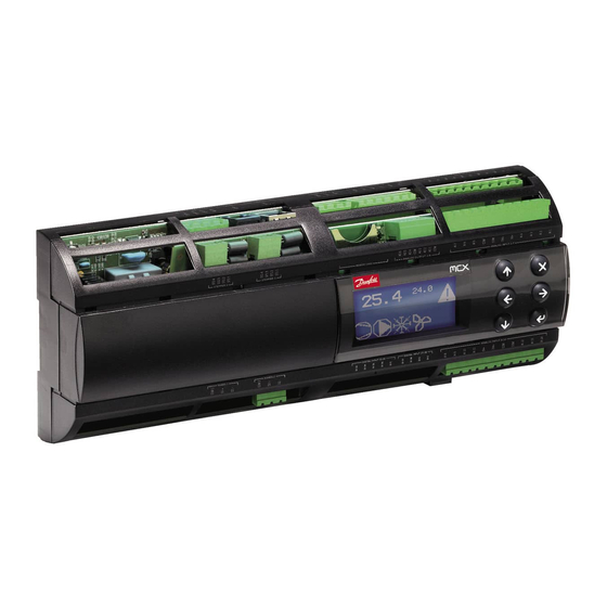
Firmware v1.04 Update Product Introduction The MCX-RTU controller is a complete solution for controlling a small to medium sized commer- cial rooftop unit. The controller provides energy efficient control of the rooftop while maintai- ning designed comfort levels and safety of the controlled space. It is also designed to comple- ment the Danfoss full store control via the connection to the AK-SM 800 series front end. -
Page 4: Specifications
All Dry contacts except DI17 (24 V AC or 230 V AC driven) AK-SM 800 Firmware required to interface with the MCX-RTU must be VG8.033 or greater and StoreView Desktop version 1.13 or greater must be used for remote access. -
Page 5: Installation
User Guide | MCX-RTU Rooftop Installation The MCX-RTU is mounted on a DIN rail with enough room to easily connect power and other interface wires. This image provides the dimensions of the MCX-RTU controller for determining space for mounting. Make sure that you allow enough space for easy routing of the required interface cables for power, inputs and outputs. -
Page 6: Connections
User Guide | MCX-RTU Rooftop Connections Wiring Diagram MCX 152V - top and bottom MCX152V - TOP COM 1 ST2 4 AK-SM 800 ST2 3 D1 + Modbus connection ST2 2 D1 - ST2 1 Not used ST1 4 ST1 3... - Page 7 AI 8 AI 7 AI 9 AI 6 AI 5 AI 10 AI 11 User Guide | MCX-RTU Rooftop 15V+ 15V+ Wiring Diagram MCX 152V - top and bottom AI 4 AI 12 AI 3 AI 2 AI 13 AI 14...
-
Page 8: Network Topology
Be sure to configure the Modbus repeater AKA 222 (code#084B2240) to the correct baud rate. MCX-RTU baud rate must be set to 38.4 K when used with the AK-SM 800. MCX-RTU cannot be on the same 485 bus with SLVs. -
Page 9: Sequence Of Operation
User Guide | MCX-RTU Rooftop Sequence of Operation Cooling Mode The Controller is in Cooling Mode when the Zone Temperature is above Cool1 Target minus two times the programmed Cool Range. At this point Free Cooling will be active if the Damper and Free Cooling are enabled. -
Page 10: Heating Mode
User Guide | MCX-RTU Rooftop Heating Mode The Controller is in Heating Mode when the Zone Temperature is below Cool1 Target minus 2x the Cool Range. Before any heating stages are activated, the fan must be proofed by either a digital input or analog input to insure the fan is operational. -
Page 11: Co2 Mode
User Guide | MCX-RTU Rooftop on. For Variable Speed Fan, the fan will run at Cooling Max Fan Speed until all stages of dehumi- dification are running at 100% capacity for the time specified in the Max Capacity Period setting. -
Page 12: Status Screens
User Guide | MCX-RTU Rooftop Status Screens Main Status Screen What the keys do on the Main Status Screen Enter – Parameter Screen – Current Alarms Down Arrow – Current Sensor Values Left Arrow – Broadcast Sensor Values Received Access Current Sensor Values from Main Status Screen using the Down Arrow button. - Page 13 User Guide | MCX-RTU Rooftop Access Broadcast Sensor Values from the Main Status Screen using the Left Arrow button. Broadcast Sensor Screen This screen shows the values that have been received via the broadcast from the AK-SM 800. The sensors that start with RH and CO2, are just that.
-
Page 14: Configuration
User Guide | MCX-RTU Rooftop Configuration The configuration screens are accessed by pressing the Enter button (lower right button) on the controller. Select Login and enter the password( default: 300) for the following screen. Note that every time the Main Status Screen is visible the password entered is cleared and must be reentered to access the password protected items. - Page 15 User Guide | MCX-RTU Rooftop To configure the controller, go to the Setup Options menu and make selections for your instal- lation. Below is a list of the Setup Options along with their definitions. Setup Options Function Default Units Fan Type Select Fan Type –...
- Page 16 User Guide | MCX-RTU Rooftop Setup Options Function Default Units Compr3 AO Type Select AO Range for Cool3(0-5,1-5,0-10,2- 10,Custom) Compr4 AO Type Select AO Range for Cool4(0-5,1-5,0-10,2- 10,Custom) Damper AO Type Select AO Range for Damper(0-5,1-5,0-10,2- 2-10 10,Custom) Custom AO Min Set Min VDC for Custom AO(0.0-10.0vdc)
- Page 17 User Guide | MCX-RTU Rooftop Next go to the Parameters menu for the screen below. The table below shows all the parameters available to edit along with their definitions. Parameters > Function Default Units General ON/OFF Master Switch (Off/On) Temperature Units...
- Page 18 User Guide | MCX-RTU Rooftop Parameters > Function Default Units General Avg RH1 Select RH1 sensor for Average(None/Local/ None Glbl1-5) Avg RH2 Select RH2 sensor for Average(None/Local/ None Glbl1-5) Avg RH3 Select RH3 sensor for Average(None/Local/ None Glbl1-5) Not Used...
- Page 19 User Guide | MCX-RTU Rooftop Parameters > Function Default Units Cool CL1 Target Cool 1 Target Temperature (10.0-40.0°C) 40.0 °C/°F CL1 PreDelay Cool 1 Pre Delay (0-240) CL1 PostDelay Cool 1 Post Delay (0-240) CL2 Target Cool 2 Target Temperature (10.0-40.0°C) 40.0...
- Page 20 User Guide | MCX-RTU Rooftop Parameters > Function Default Units Heat Reclaim HR1 PreDelay Heat Reclaim 1 Pre Delay (0-240) HR1 PostDelay Heat Reclaim 1 Post Delay (0-240) HR2 Target Heat Reclaim 2 Target Temperature (10.0- 22.2 °C/°F 40.0°C) HR2 PreDelay...
- Page 21 User Guide | MCX-RTU Rooftop HT Night Set- Aux Heat Mode Night Setback (0.0-30.0K) back Gas Fan Delay Gas - Fan Delay Off (0-600) HT SupplyAir Aux Heat Mode Supply Air Target for VS 30.6 °C/°F Fan (0.0-100.0°C) HT Min Fan Aux Heat Mode Min Fan Speed (0.0-100.0)
- Page 22 User Guide | MCX-RTU Rooftop HUM Parameters > Function Default Units Dehumd Cp2 Press Target Dehumidification Compr 2 Pressure Target bar/psi (0.0-100.0) Cp3 Press Target Dehumidification Compr 3 Pressure Target bar/psi (0.0-100.0) Cp4 Press Target Dehumidification Compr 4 Pressure Target bar/psi (0.0-100.0)
- Page 23 User Guide | MCX-RTU Rooftop Parameters > Function Default Units Alarm Config Zone - Low Temp Zone Temp Low Alarm (0.0-40.0) °C/°F Zone - Delay Zone Temp Delay (0-240) CO2 - High Level CO2 High Alarm (0-2000) 1000 CO2 - Delay...
-
Page 24: Overrides
User Guide | MCX-RTU Rooftop Overrides Overrides OV1 and OV2, are used to enable Night Setback and Title24 modes. Overrides OV3 – OV8 are used to place the specific features (as shown below) in manual opera- tion. The override value will be displayed by stage, %, OFF, ON, etc. For analog outputs a value of zero shuts down the feature and 100 will enable 100% of the feature overridden. -
Page 25: Schedule Enable
User Guide | MCX-RTU Rooftop Schedule Enable How it works On the AK-SM 800, select the MCX-RTU to assign a schedule and select the Schedule tab. (Note: it is preferred to set up schedules under configuration -> Refrigeration -> Schedules – see page 28) If no schedule has been setup, you will see a screen, similar to the one below. -
Page 26: Backup / Restore
The Backup/Restore feature menu items are located in the Service Menu. Backup - After you have inserted a SD card into the MCX-RTU, go to the Service Menu and select Backup. Allow a minute for the backup to complete. The backup file is saved to the SD card with the Modbus address of the MCX-RTU as part of the name. -
Page 27: Data Logging
Value of Global Outdoor Temp The Data Log file may be converted to an Excel file by using the DecodeLog converter program. The program can be requested from Danfoss Tech Support. RS8KE102 | 27 © Danfoss | ADAP-KOOL® | 2018.11... -
Page 28: Broadcast Configuration
Configure Schedules The schedules used by the MCX-RTU are setup on the AK-SM 800. The schedule status of the first 16 schedules are broadcasted to all the MCX-RTU controllers. There is no assignment of individu- al MCX-RTU at the AK-SM 800. The schedule assignments are only configured in the MCX-RTUs. -
Page 29: Ak-Sm 800 Mcx-Rtu Commission
User Guide | MCX-RTU Rooftop AK-SM 800 MCX-RTU To commission a MCX-RTU controller on a AK-SM 800, use the following steps. Commission Connect to the AK-SM 800 using Storeview Desktop or a web browser and log in. Next go to Configuration. - Page 30 User Guide | MCX-RTU Rooftop This starts the Layout wizard. Click the Right Arrow on the upper right corner. Enable the MODBUS-RS485 channel by selecting Disabled next to MODBUS-RS485 and change to Enabled. Click the arrow to advance to next screen RS8KE102 | 30 ©...
- Page 31 User Guide | MCX-RTU Rooftop Click the Scan button to start the scanning process. Once scanning is complete a list of the HVAC controllers are displayed. Click Right Arrow (upper right corner) to proceed. RS8KE102 | 31 © Danfoss | ADAP-KOOL® | 2018.11...
- Page 32 User Guide | MCX-RTU Rooftop Now add additional offline controllers or proceed. To add offline controllers, follow the instruc- tions on the screen. Click the Right Arrow (upper right corner) to proceed. View a summary of the HVAC controllers attached to the AK-SM 800. If correct click on the Right Arrow (upper right corner) .
- Page 33 User Guide | MCX-RTU Rooftop Pop Up indicating completion using HVAC Layout Wizard. RS8KE102 | 33 © Danfoss | ADAP-KOOL® | 2018.11...
-
Page 34: Io List
User Guide | MCX-RTU Rooftop IO List I/O CONFIGURATION ANALOG INPUTS Type Zone Temperature -30.0°C 170.0°C PT1000 Supply Air -30.0°C 170.0°C PT1000 Return Air -30.0°C 170.0°C PT1000 Zone RH 0.0 % 100.0 % 0-5 V Outdoor RH 0.0 % 100.0 %... - Page 35 User Guide | MCX-RTU Rooftop DIGITAL INPUTS Type Cool 4 Proof N.O. (Located on Expansion Module) N.C. (Located on Expansion Module) N.C. (Located on Expansion Module) N.C. (Located on Expansion Module) N.C. (Located on Expansion Module) N.C. (Located on Expansion Module) N.C.
- Page 36 User Guide | MCX-RTU Rooftop Danfoss can accept no responsibility for possible errors in catalogues, brochures and other printed material. Danfoss reserves the right to alter its products without notice. This also applies to products already on order provided that such alternations can be made without subsequential changes being necessary in specifications already agreed.