
Summary of Contents for VeriFone Forecourt Controller Interface
- Page 1 Forecourt Controller Forecourt Controller Interface Interface Installation Guide Date: August 11, 2016...
- Page 3 - without written permission of the publisher. The content of this document is subject to change without notice. The information contained herein does not represent a commitment on the part of Verifone. All features and specifications are subject to change without notice.
- Page 4 Forecourt Controller Interface Installation Guide Revision History Date Description June 25, 2012 Initial documentation release. November 2, 2012 Added Warning below. Also, added new part numbers for the FCI kit and manual. May 1, 2014 Added references to Commander Site Controller and current loop board changes.
- Page 5 4. Installation measures must be taken to prevent physical damage to the power supply cord, including proper routing of the power supply cord. 5. When replacing the cover on the Forecourt Controller Interface, tighten the thumbscrews securely with a screwdriver.
-
Page 7: Table Of Contents
Preparing to Install ....... 13 Installing the Forecourt Controller Interface Box... . 14 Installing the Boards . - Page 8 Forecourt Controller Interface Installation Guide August 11, 2016...
-
Page 9: Introduction
The Forecourt Controller Interface allows fuel and DCR communications between the dispensers and the Commander Site Controller. Note: The Forecourt Controller Interface is not used for fuel communication for Tokheim, Bennett, and sites required to use the Smart Fuel Controller (SFC). -
Page 10: Before You Install
Carefully inspect the shipping carton and its contents for any damage that might have occurred during shipment. If anything appears damaged, immediately file a claim with the shipping company or carrier and notify your Verifone representative. Never use damaged equipment. A shock or fire hazard may exist if equipment is energized in a damaged condition. -
Page 11: General Requirements
General Requirements Before you start, read the following important information: 1. Changes or modifications not expressly approved by Verifone, Inc., could void the user’s authority to operate this equipment. 2. This equipment is not intended to be repaired by the user. All repairs must be performed by an Authorized Service Technician or a Verifone VASC. -
Page 12: Safety Instructions
6. Installation measures must be taken to prevent physical damage to the power supply cord, including proper routing of the power supply cord. 7. Do not connect the Forecourt Controller Interface unit to the AC power until the installation is complete. - Page 13 Forecourt Controller Interface Installation Guide DANGER: Disconnect all power to this equipment during installation, service, or maintenace. Tag breakers to prevent others from reconnecting power. DANGER: This equipment is to be installed in an indoor location only. Do not install this equipment in a hazardous location.
- Page 14 Forecourt Controller Interface Installation Guide August 11, 2016...
-
Page 15: Installing The Forecourt Controller Interface Box
General Requirements section in Chapter 1.) Determining a Location The Forecourt Controller Interface box must be mounted in an indoor location. Locate the box at least 18 inches above the floor in an area where liquids will not be spilled onto it. -
Page 16: Existing Equipment
If there is an existing distribution box at the site, disconnect the cables from the box and remove it. It is not used with the Forecourt Controller Interface. The Forecourt Controller Interface box can be mounted in the same location. -
Page 17: Wayne Sites
Forecourt Controller Interface Installation Guide Wayne Sites If there is a Wayne distribution box, disconnect all the dispenser control cables. – The terminals on the distribution box are marked ( ) and ( ); mark the positive ) wires. The dispenser control cables will be reconnected to the FCI. Also, disconnect the cables that go to the Electronics Cabinet. - Page 18 Forecourt Controller Interface Installation Guide Wayne Electronics Cabinet August 11, 2016...
-
Page 19: Tokheim Sites
(P/N 13581-01) to connect the Commander Site Controller to the VXDHC or DHC. Note: If the Verifone Site Controller is being replaced rather than a new installation, use the existing VXDHC/DHC box, cable and connector as described above. -
Page 20: Bennett Sites
(P/N 13641-01) to connect the Commander Site Controller to the 515 Box. Note: If the Verifone Site Controller is being replaced rather than a new installation, use the existing 515 box, cable and connector as described above. Bennett 515 Box... -
Page 21: Preparing To Install
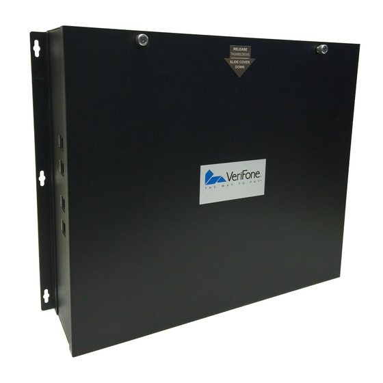
Forecourt Controller Interface Installation Guide Preparing to Install Before you begin the installation, loosen the two thumbscrews that attach the cover of the FCI enclosure. Push the cover forward 1/2- inch and lift. Thumbscrews (2) August 11, 2016... -
Page 22: Installing The Forecourt Controller Interface Box
Installing the Boards Note: The Forecourt Controller Interface box come with one current loop board installed. Additional boards must be ordered separately. Installing the Current Loop Boards The current loop boards (Kit # 29721-01) support both current loop and RS232 communications. - Page 23 Forecourt Controller Interface Installation Guide 2. Locate the mounting posts on the FCI box. Mounting Post Locations August 11, 2016...
- Page 24 Forecourt Controller Interface Installation Guide 3. Position the first current loop board over the mounting posts in location 1 above, and secure the board to the posts using the four screws (P/N SCR-0001) provided with the Current Loop Board kit.
- Page 25 Installing the RS485 Boards The RS485 Board 8-Channel Interface Kit (Kit # 29376-01) supports RS485 communications and must be used for Dresser Wayne CAT/Ovation, Tokheim DPT, Bennett Secure Payment Module (SPM), and Verifone Secure PumpPAY installations. To install the RS485 boards: 1.
- Page 26 Forecourt Controller Interface Installation Guide 2. Locate the mounting posts on the FCI box. Mounting Post Locations August 11, 2016...
- Page 27 Forecourt Controller Interface Installation Guide 3. Locate the four screws (P/N SCR-0001) provided with the RS485 Board kit. 4. Position the RS485 board over the mounting posts in location 1 above. Secure the board to the posts using the four screws.
-
Page 28: Mounting The Unit
Forecourt Controller Interface Installation Guide Mounting the Unit Before you mount the unit, remove one or more of the 1-inch knockouts into which to install 1-inch conduit fittings for routing the dispenser control wires. The number of knockouts to be removed will depend on how many dispenser control wires there are. - Page 29 Forecourt Controller Interface Installation Guide Forecourt Controller Interface Box Ports Conduit Fitting Mount the FCI box securely to the wall with toggle bolts through the pre-drilled tabs. Screw Screw Holes Holes Rear View To mount the FCI Box: 1. Using the box as a template, mark the hole placement for the four toggle bolts on the desired wall location where the distribution boards can be easily connected to the existing dispenser control cables.
-
Page 30: Connecting The Dispenser Control Cables
Forecourt Controller Interface Installation Guide 2. For mounting into drywall, use four 1/8-inch toggle bolts, 3 inches long. To install the toggle bolts: a. Open a hole of the recommended size (usually 3/8 or 1/2 inch) at the center of the holes marked in step 2. -
Page 31: Connecting To Current Loop Boards
Forecourt Controller Interface Installation Guide 3. Route the dispenser control wires through the conduit fittings installed earlier. Conduit Fitting Dispenser Control Wires Connecting to Current Loop Boards 1. Locate the loop cables provided with the Current Loop Board kit. Eight loop cables can be connected to each distribution board. - Page 32 Forecourt Controller Interface Installation Guide 3. Using wire nuts, connect one dispenser control wire to each FCI current loop wire. Connect positive ( ) to positive. Repeat for each current loop distribution board. Note that it might be necessary to reverse some of the connections after you check the communications from the FCI to the dispensers.
- Page 33 Forecourt Controller Interface Installation Guide 5. Connect the power cable and one of the communications ribbon cables to the current loop board. Connect the ribbon cables in the order shown. Board 1 Board 2 Board 3 Board 4 Ribbon Power...
-
Page 34: Connecting To Rs485 Boards
Forecourt Controller Interface Installation Guide Connecting to RS485 Boards Note: At sites with Tokheim and Bennett, all of the drain or ground wires are tied together to a single wire connected to chassis ground using a wire nut as shown below. - Page 35 Forecourt Controller Interface Installation Guide 2. Strip 1/4-inch of insulation from each DCR wire and twist the ends. Connect the wires to the connector blocks and secure by tightening the screws on the connector block. Connector Block with 2 Wires —...
- Page 36 Forecourt Controller Interface Installation Guide 4. Connect the power cable and one of the ribbon cables to the current loop board. Connect the ribbon cables in the order shown. Board 1 Board 2 Board 3 Board 4 Power Ribbon Cable Cable 5.
-
Page 37: Connecting To A Tokheim Ted
Forecourt Controller Interface Installation Guide Connecting to a Tokheim TED The TED will connect to a single channel of an RS485 board in the FCI. Tokheim uses three wires for DPT connections (Positive, Negative and Ground). The single ground wire coming into the FCI from the TED should be grounded to the lower left mounting screw of the RS485 board. -
Page 38: Completing The Installation
Completing the Installation This section provides instructions for closing up the box, connecting communications cables between the Forecourt Controller Interface and the Commander Site Controller, and connecting to the AC power supply. 1. Replace the cover on the enclosure and secure by tightening the two thumbscrews. - Page 39 Forecourt Controller Interface Installation Guide 6. Plug the female end of the power cord into the power connector on the FCI box. Make sure the connector locks securely in place. 7. Plug the other end of the power cord into the dedicated AC outlet.