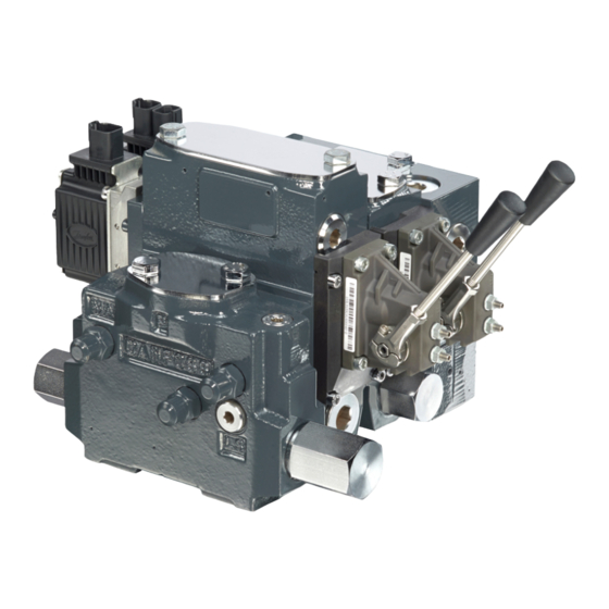
Danfoss PVG 120 Technical Information
Proportional valve group
Hide thumbs
Also See for PVG 120:
- Service manual (50 pages) ,
- Technical information (48 pages) ,
- Installation manual (8 pages)
Table of Contents
Advertisement
Quick Links
Download this manual
See also:
Service Manual
Advertisement
Table of Contents

Related Manuals for Danfoss PVG 120


Summary of Contents for Danfoss PVG 120
- Page 1 Technical Information Proportional Valve Group PVG 120 powersolutions.danfoss.com...
- Page 2 Date Changed March 2017 minor updates 1002 Mar 2014 Chapters re-order, Modules selection chart Dec 2013 Converted to Danfoss layout – DITA CMS 2006 - 2012 Various updates AB - IC Apr 2006 New edition 520L0356 | BC00000040en_US1002 © Danfoss | March 2017...
-
Page 3: Table Of Contents
PVB, Basic Module..................................24 PVLP, Shock Valve Characteristic (with Pressure Relief Valve)..................26 PVLP/PVLA, Suction Function..............................27 Hydraulic system examples Example of PVG 120 with variable displacement pump....................28 Example of PVG 120 with fixed displacement pump......................29 Other operating conditions Hydraulic fluids for PVG................................30 Particle Content, Degree of Contamination.........................30... - Page 4 PVHC, High Current Actuator..............................39 PVE, Electrical Actuation................................39 PVT, tank side module..................................39 PVAS, Assembly Kit..................................40 PVG 120 Modules Selection Chart PVG 120 module selection chart.............................. 41 Order specification Ordering of modules for oil flow exceeding 180 l/min [47.6 US gal/min]..............45 Order Form....................................... 45 Reordering....................................46 520L0356 | BC00000040en_US1002 ©...
-
Page 5: Literature Reference For Pvg Products
Technical Information PVG 120 Proportional Valve Group Literature reference for PVG products Literature reference Literature title Type Order number PVG 32 Proportional Valve Group Technical Information 520L0344 PVG 100 Proportional Valve Group Technical Information 520L0720 PVG 120 Proportional Valve Group... -
Page 6: General Information
General Information Valve System Load sensing proportional valve type PVG 120 is a combined directional and flow control valve which is supplied as a valve group consisting of modules specified to match particular customer needs. The flexible nature of this valve will allow an existing valve bank to be easily adapted to suit changes in requirements. -
Page 7: Basic Module - Pvb
Technical Information PVG 120 Proportional Valve Group General Information Basic Module – PVB • Integrated pressure compensator in channel P • Interchangeable spools • Depending on requirements the basic module can be supplied with: Shock/suction valves ‒ Adjustable LS pressure limiting valve for ports A and B ‒... -
Page 8: Remote Controls Units
Technical Information PVG 120 Proportional Valve Group General Information Remote Controls Units PVRE, electrical control unit, 162F… PVRH, hydraulic control unit, 155N… 155N0003 155N0001 155N0004 155N0005 155N0002 PVREL, electrical control unit, 155U… PVRES, electrical control unit, 155B… Prof 1, 162F…... -
Page 9: Function
PVG 120 Proportional Valve Group Function PVG 120 with PVP Open Center When the pump is started and the main spools (1) in the individual basic modules are in neutral position, oil flows from the pump, through connection P, across the pressure adjustment spool (2) to tank. -
Page 10: Pvg 120 Sectional View
Technical Information PVG 120 Proportional Valve Group PVG 120 sectional view PVG 120 sectional view V310100.A Legend: 1 – Main spool 7 – Shock and suction valve PVLP 2 – Pressure adjustment spool in PVP 8 – Suction valve PVLA 3 –... -
Page 11: Safety In Application
Technical Information PVG 120 Proportional Valve Group Safety in application All types of control valves (incl. proportional valves) can fail, thus the necessary protection against the serious consequences of function failure should always be built into the system. For each application an assessment should be made for the consequences of pressure failure and uncontrolled or blocked movements. -
Page 12: Control System Example
Technical Information PVG 120 Proportional Valve Group Safety in application Control system example Example of a control system for manlift using PVE Fault monitoring input signals and signals from external sensors to ensure the PLUS+1 main ® controllers correct function of the manlift. - Page 13 PVG 100 – alternative LS dump or pilot supply disconnect: • PVPP, pilot oil supply shut off • External cartridge valve connecting LS pressure or main pressure to tank PVG 120 – pump disconnect / block for variable pumps: 520L0356 | BC00000040en_US1002 | 13 © Danfoss | March 2017...
-
Page 14: Examples Of Wiring Block Diagram
Technical Information PVG 120 Proportional Valve Group Safety in application • PVPE, full flow dump for the PVG 120 • External cartridge valve connecting LS pressure to tank Examples of wiring block diagram Example of a typical wiring block diagram using PVEH with neutral power off switch and fault monitoring output for hydraulic deactivation. - Page 15 Technical Information PVG 120 Proportional Valve Group Safety in application Example of fault monitoring for deactivation of the hydraulic system with extra fault inputs using the PVE’s with DI (Direction Indication) function. Emergency Man present Stop switch PVE 1 Neutral detection / Supply control...
-
Page 16: Technical Data
Technical Information PVG 120 Proportional Valve Group Technical Data PVG 120 technical data continuous 350 bar [5075 psi] Maximum pressure Port P 400 bar [5800 psi] intermittent 400 bar [5800 psi] Port A/B 25 bar/40 bar [365/580 psi] Port T, static/dynamic 240/300 l/min [63.4/79.3 US gal/min]... -
Page 17: Pvh, Hydraulic Actuation
The hysteresis is stated at rated and f = 0,02 Hz for a cycle. One cycle includes the movement from neutral position to max. spool travel direction A, via neutral position to max. spool travel in direction B, and back to neutral position. Further information can be obtained by contacting the Danfoss Power Solutions Sales Organization. - Page 18 Technical Information PVG 120 Proportional Valve Group Technical Data PVPE, electrical relief valve, normally open (continued) 12 to 75 mm /s [65 to 347 SUS] Oil viscosity Operating range 4 mm /s [39 SUS] Min. viscosity 460 mm /s [2128 SUS] Max.
-
Page 19: Pveo, On-Off
Technical Information PVG 120 Proportional Valve Group Electrical Actuation PVEO, ON-OFF The main features of PVEO: • Compact • Robust operation • Hirschmann or AMP connector • Low electrical power V310185.A PVEO parameters 12 V 24 V Supply voltage U... -
Page 20: Pveh, Inductive Transducer (Lvdt - Linear Variable Differential Transformer)
Technical Information PVG 120 Proportional Valve Group Electrical Actuation The main features of PVEH: • Inductive transducer • Integrated pulse width modulation • Low hysteresis • Fast reaction time • Hirschmann or AMP connector • Fault monitoring with transistor output for signal source •... -
Page 21: Pveh, Pulse Width Modulation (Integrated)
Technical Information PVG 120 Proportional Valve Group Electrical Actuation PVEH, Pulse Width Modulation (Integrated) Positioning of the main spool in PVEH is based on the pulse width modulation principle. As soon as the main spool reaches the required position, modulation stops and the spool is locked in position. -
Page 22: Pveh, Connection To Fault Monitoring Output
Technical Information PVG 120 Proportional Valve Group Electrical Actuation Fault monitoring specification † LED light Memory† Type Fault Delay Error mode Error Fault monitoring before output output on error out status PVE* PVEO No fault monitoring PVEH Active 500 ms No fault <... -
Page 23: Technical Characteristics
Technical Information PVG 120 Proportional Valve Group Technical Characteristics General All characteristics and values in the technical information are typical measured results. For the hydraulic system a mineral based hydraulic oil with a viscosity of 21mm /s [102 SUS] and a temperature of 50°C [122°F] was used. -
Page 24: Pvb, Basic Module
Technical Information PVG 120 Proportional Valve Group Technical Characteristics PVB, Basic Module Oil flow characteristics = Signal voltage; = Supply voltage Port conditions at rated oil flow Port Metric units US units 65 l/min [17.2 US gal/min] 95 l/min [25.1 US gal/min] 130 l/min [34.3 US gal/min]... - Page 25 Technical Information PVG 120 Proportional Valve Group Technical Characteristics Load independent oil flow Pressure drop Q T in neutral position /spools with open neutral position, (p). The oil flow Q is shown as a function of the load (p). Pressure drop A/B → T at full spool travel 520L0356 | BC00000040en_US1002 | 25 ©...
-
Page 26: Pvlp, Shock Valve Characteristic (With Pressure Relief Valve)
Technical Information PVG 120 Proportional Valve Group Technical Characteristics Pressure drop A/B → T, spools with open neutral position PVLP, Shock Valve Characteristic (with Pressure Relief Valve) PVLP, shock valve characteristic (with Pressure Relief Valve) The shock valve PVLP is designed to absorb shock effects. Consequently, it shall not be used as a pressure relief valve. -
Page 27: Pvlp/Pvla, Suction Function
Technical Information PVG 120 Proportional Valve Group Technical Characteristics PVLP/PVLA, Suction Function PVLP/PVLA, suction function characteristic 520L0356 | BC00000040en_US1002 | 27 © Danfoss | March 2017... -
Page 28: Hydraulic System Examples
Technical Information PVG 120 Proportional Valve Group Hydraulic system examples Example of PVG 120 with variable displacement pump 520L0356 | BC00000040en_US1002 28 | © Danfoss | March 2017... -
Page 29: Example Of Pvg 120 With Fixed Displacement Pump
Technical Information PVG 120 Proportional Valve Group Hydraulic system examples Example of PVG 120 with fixed displacement pump 520L0356 | BC00000040en_US1002 | 29 © Danfoss | March 2017... -
Page 30: Other Operating Conditions
Water-oil emulsions (HFB fluids) • Oil-water emulsions (HFAE fluids) Biodegradable fluids PVG 120 valves can be used in systems using rape-seed oil. The use of rape-seed oil is conditional on: • it complying with the demands on viscosity, temperature and filtration, etc. •... -
Page 31: Conversion Factors
Pressure filters must be fitted to suit max. pump oil flow. Internal filters The filters built into PVG 120 are not intended to filter the system but to protect important components against large particles. Such particles can appear in the system as a result of pump damage, hose fracture, use of quick- couplings, filter damage, starting up, contamination, etc. -
Page 32: Dimensions
Technical Information PVG 120 Proportional Valve Group Dimensions PVG 120 dimensions 158[6.22] 152[5.98] [1.10] DIN 43650 105[4.13] 35.5 33.5 33.5 PG 11 [prop.] [1.398] [1.319] 15[0.59] [1.319] 25[0.98] 55.5[2.185] PG 9 [on-off ] max.61[2.40] 27[1.06] max. 262.5[10.335] 21.5[0.846] 111[4.37] 27.8 [1.094]... - Page 33 Technical Information PVG 120 Proportional Valve Group Dimensions Port ¾ in SAE flange (415 bar) ∕ –12 UN O-ring Boss (6020 psi) 1 in SAE flange (415 bar) ∕ –12 UN O-ring Boss (6020 psi) G ¼ ½–20 UNF ∕...
-
Page 34: Pvm, Lever Positions
Technical Information PVG 120 Proportional Valve Group Dimensions PVM, Lever Positions Base with an angle of 37.5° Base with an angle of 22.5° V310018.A V310014.A 520L0356 | BC00000040en_US1002 34 | © Danfoss | March 2017... -
Page 35: Modules And Code Numbers
Technical Information PVG 120 Proportional Valve Group Modules and Code Numbers PVP and PVPV, Pump Side Modules Port type Symbol Description Code number Open center PVP for pumps with fixed displacement. Metric flange 155G5021 Pressure gauge connection. SAE flange 155G5037... -
Page 36: Pvb, Basic Modules
Technical Information PVG 120 Proportional Valve Group Modules and Code Numbers PVB, Basic Modules Symbol Description Code number No facilities for Facilities for shock shock valves A/B valves A/B (high (low modules) modules) Pressure compensated Metric flange 155G6014 155G6005 Port connections:... -
Page 37: Pvla, Suction Valve
Technical Information PVG 120 Proportional Valve Group Modules and Code Numbers PVLA, Suction Valve Symbol Code number 155G1065 PVLP, Shock and Suction Valves for A/B Port Connections Symbol Fixed setting Code number bar [psi] [725] 155G0050 [1100] 155G0075 [1450] 155G0100... -
Page 38: Pvbs, Main Spools
Technical Information PVG 120 Proportional Valve Group Modules and Code Numbers PVBS, Main Spools Symbol ISO Symbol Description Code number Size 65 l/min 95 l/min 130 l/min 180 l/min [17.2 US [25.1 US [34.3 US [47.6 US gal/min] gal/min] gal/min] gal/min] 4-way, 3-position. -
Page 39: Pvhc, High Current Actuator
Technical Information PVG 120 Proportional Valve Group Modules and Code Numbers PVHC, High Current Actuator Symbol Description Code number Hirschmann Deutsch PVHC 12 V – – 11110597 24 V – – 11110598 PVE, Electrical Actuation Symbol Description Code number Hirschmann... -
Page 40: Pvas, Assembly Kit
Technical Information PVG 120 Proportional Valve Group Modules and Code Numbers PVT, tank side module (continued) Port type Symbol Description Code number Lower part of PVE, Mounting thread 155G7040 pilot oil supply for electrical actuations. metric Filter mesh: 125 µm... -
Page 41: Pvg 120 Modules Selection Chart
Technical Information PVG 120 Proportional Valve Group PVG 120 Modules Selection Chart PVG 120 module selection chart PVG 120 modules exploded view V310173.A PVB, high basic module O-ring Metric flange Weight flange Boss kg [lb] Facilities for shock valves AB... - Page 42 Technical Information PVG 120 Proportional Valve Group PVG 120 Modules Selection Chart Accessory modules for PVB Code number Weight, kg [lb] Plug, PVBP 155G6081 0.4 [0.9] press. relief valve, PVBR 155G6080 External LS connection, PVBC 155G6082 Module for oil flow > 180 l/min [47.6 US gal/min], PVBU...
- Page 43 Technical Information PVG 120 Proportional Valve Group PVG 120 Modules Selection Chart PVP, pump side module Code number O-ring Metric flange Weight Boss flange kg [lb] Open Excl. PVPD, PVPH, PVPE 155G5023 155G5037 155G5021 10.0 [22.1] centre For PVB-oil flow > 180 l/min [47.6...
- Page 44 Technical Information PVG 120 Proportional Valve Group PVG 120 Modules Selection Chart PVLP, shock and suction valve A/B (continued) Pressure setting 2550 155G0175 2900 155G0200 3250 155G0225 3650 155G0250 4000 155G0275 4350 155G0300 4700 155G0325 5100 155G0350 5400 155G0375 5800 155G0400 0.175 [0.386]...
-
Page 45: Order Specification
The code number of the spring and plug is 155G6035 (PVBU, accessory module). Order Form An order form for PVG 120 hydraulic valve is shown on next page. The form can be obtained from the Danfoss Power Solutions Sales Organisation. -
Page 46: Reordering
Reordering The space at the top right-hand corner of the form is for Danfoss to fill in. The code number for the whole of the specified valve group (PVG No.) is entered here. In the event of a repeat order all you have to do is enter the number Danfoss has given on the initial confirmation of order. - Page 47 Technical Information PVG 120 Proportional Valve Group 520L0356 | BC00000040en_US1002 | 49 © Danfoss | March 2017...
- Page 48 Phone: +86 21 3418 5200 Danfoss can accept no responsibility for possible errors in catalogues, brochures and other printed material. Danfoss reserves the right to alter its products without notice. This also applies to products already on order provided that such alterations can be made without changes being necessary in specifications already agreed.