
Related Manuals for Samsung MTP02P Series


Summary of Contents for Samsung MTP02P Series
- Page 1 MTP02P Series Installation Manual Describes product installation and requirement procedure. Document Version 1.0 April 2018 Document Number: 2600-00M896GAA...
- Page 2 SAMSUNG Electronics Co., Ltd., its subsidiaries or employees for any direct or indirect loss or damage caused by omissions from or inaccuracies in this document. SAMSUNG Electronics Co., Ltd. reserves the right to change details in this publication without notice. SNMTC-v3-0312 This manual should be read and used as a guideline for properly installing and/or operating the product.
-
Page 3: Table Of Contents
Identification Tag Attachment ....................70 Cabling Diagram ..........................71 Grounding ............................72 Connecting Ground Cable ......................72 Power Cabling ..........................76 Connecting Power Cable ......................77 External Interface Connection ....................... 80 MTP02P Series Installation Manual v1.0 Copyright © 2018, All Rights Reserved. - Page 4 Inspect the Installation Appendix A Acronyms Appendix B Clean the Optical Connectors Introduction ........................... 89 Measure the Optical Output and Connecting the Optical Connector ........89 Appendix C Standard Torque MTP02P Series Installation Manual v1.0 Copyright © 2018, All Rights Reserved.
- Page 5 Fixing MMU on the Pole_Up Tilting Installation (2) ............... 42 Leveling MMU on the Pole_Up Tilting Installation ................ 43 Plate Adjustment ..........................43 MMU Marking Dimensions ......................45 Marking_Wall Type ........................46 Drilling & Anchoring (1) ........................47 MTP02P Series Installation Manual v1.0 Copyright © 2018, All Rights Reserved.
- Page 6 Connecting Power Cable (3) ......................79 Connecting LINK Cable (1) ......................80 Connecting LINK Cable (2) ......................81 Connecting LINK Cable (3) ......................82 Installation Inspection Procedure ....................84 MTP02P Series Installation Manual v1.0 Copyright © 2018, All Rights Reserved.
- Page 7 Construction Situation Check list ....................85 Table 30. Standard Torque Value for Fastening Bolts ................... 91 Table 31. Brass Bolts Torque Value........................ 91 Table 32. Connector Connection Torque Value ..................... 91 MTP02P Series Installation Manual v1.0 Copyright © 2018, All Rights Reserved.
-
Page 8: Preface
This manual describes how to install the 2.5 GHz MMU including how to connect cables. This manual includes the following 2.5 GHz MMU: MTP02P-41A Conventions in this Document Samsung Networks product documentation uses the following conventions. Symbols Symbol Description Indicates a task. -
Page 9: Revision History
This annex describes the procedure of cleaning the optical Connectors connector and cleaning tool. Appendix C Standard Torque This annex describes the standard torque when fastening the bolt. Related Documentation LTE SMBS System Description MTP02P Series Installation Manual v1.0 Copyright © 2018, All Rights Reserved. -
Page 10: Personal And Product Safety
Installation Installation must be carried out by trained and competent engineers only. All relevant safety measures should be taken to ensure equipment is not connected to MTP02P Series Installation Manual v1.0 Copyright © 2018, All Rights Reserved. - Page 11 The anti-static wrist strap and cord must be checked at regular intervals for their suitability for use. Grounding To comply with EN 60950, the equipment must be connected to a safety MTP02P Series Installation Manual v1.0 Copyright © 2018, All Rights Reserved.
- Page 12 Devices that are not marked according to the relevant national safety standards may produce hazardous conditions on the network. Product Disposal To reduce the environmental impact of products, Samsung has joined WEEE compliance activities. The WEEE symbol on the product indicates that the product is covered by the European Directive 2002/96/CE for the disposal of Waste Electrical and Electronic Equipment (WEEE).
- Page 13 - Connect the equipment into an outlet on a circuit different from that to which the receiver is connected. - Consult the dealer or an experienced radio/TV technician for help. MTP02P Series Installation Manual v1.0 xiii Copyright © 2018, All Rights Reserved.
-
Page 14: Equipment Markings
The system must be installed in a restricted area, and make sure the work is done by personnel properly trained for the job. Protective earth MMU should be grounded. MTP02P Series Installation Manual v1.0 Copyright © 2018, All Rights Reserved. -
Page 15: Chapter 1 Before Installation
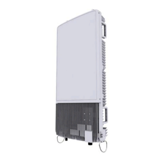
System Configuration and Interface MMU Configuration The configuration of MMU is as follows. MMU Configuration Unit: in. (mm) [Top View] 19.7 (500) [Left View] [Front View] [Right View] [Rear View] [Bottom View] MTP02P Series Installation Manual v1.0 Copyright © 2018, All Rights Reserved. -
Page 16: Mmu Interface
Confidential Chapter 1 Before Installation MMU Interface The interface structure of MMU is as follows. MMU Interface [MMU Bottom View] Ground Terminal DC_PWR LINK MTP02P Series Installation Manual v1.0 Copyright © 2018, All Rights Reserved. -
Page 17: Specifications
5~100 Hz, 0.15 grms (Telcordia GR-63-CORE) Vibration in Use 5~200 Hz, 0.89 grms (Telcordia GR-63-CORE) Transportation Vibration FCC part 15 subpart B Safety EN 60950-1 EN 60950-22 FCC part27 MTP02P Series Installation Manual v1.0 Copyright © 2018, All Rights Reserved. -
Page 18: Cautions For Installation
When operator installs the MMU, the MMU must be within the protective angle (left/right side 45° each from the central axis) to prevent the MMU from lightning MTP02P Series Installation Manual v1.0 Copyright © 2018, All Rights Reserved. -
Page 19: After Installing
Make sure that worker does not damage installed cables while cleaning the system. While cleaning the power supply device, take caution that the device does not come in contact with foreign objects that may cause power failure. MTP02P Series Installation Manual v1.0 Copyright © 2018, All Rights Reserved. -
Page 20: Installation Tools
Tape measure for length measurement Level Normal For horizontality of MMU, and so on Power Extension Cable 100 ft. Basic tool Heating Gun Shrinking heat shrink tube 122~572°F (50~300°C) MTP02P Series Installation Manual v1.0 Copyright © 2018, All Rights Reserved. - Page 21 Should be marked ‘Permanent’ Permanent Marker After system installation, I-marking on the pen To mark the site ID, Name on the name (Black Color, 2 mm Tip) plate, and so on. MTP02P Series Installation Manual v1.0 Copyright © 2018, All Rights Reserved.
- Page 22 The required installation tools may vary depending on the conditions at the site. In addition to the basic tools, a protractor, ladder, safety equipment, cleaning tools, and so on should also be prepared in consideration of the site conditions. MTP02P Series Installation Manual v1.0 Copyright © 2018, All Rights Reserved.
-
Page 23: Chapter 2 Installing System
Installing the system with the power switch ON may cause system damage or fatal human injury when connecting or disconnecting the cables. To prevent the risk of electrical shock do not wear accessories such as watches and rings. MTP02P Series Installation Manual v1.0 Copyright © 2018, All Rights Reserved. -
Page 24: System Arrangement
H: 41.3 (1050) [Top View] [Front View] The dimensions of the front of the MMU change according to the tilt angle, and the maximum dimensions are described in the figure below. MTP02P Series Installation Manual v1.0 Copyright © 2018, All Rights Reserved. -
Page 25: Mmu Arrangement_Pole Type_Up/Down Tilting
When fixing a mounting bracket, the length of stud bolts are 220 mm for the pole diameter 50~100 A. Pole Size (Diameter) Length of Stud Bolt 50 A, 65 A, 80 A, 90 A, 100 A 220 mm Pole Stud Bolt Size MTP02P Series Installation Manual v1.0 Copyright © 2018, All Rights Reserved. - Page 26 H: 41.3 (1050) [Top View] [Front View] The dimensions of the front of the MMU change according to the tilt angle, and the maximum dimensions are described in the figure below. MTP02P Series Installation Manual v1.0 Copyright © 2018, All Rights Reserved.
-
Page 27: Mmu Arrangement_Wall Type_Up/Down Tilting
Confidential Chapter 2 Installing System MMU Arrangement_Wall Type_Up/Down Tilting Unit: in. (mm) [Up Tilting 15 [Down Tilting 15 21.8 (553) 20.4 (519) [Left View] [Right View] MTP02P Series Installation Manual v1.0 Copyright © 2018, All Rights Reserved. -
Page 28: Unpacking And Transporting
Unpack the inner packaging after each system is placed on its installation location. Scrap by-products (packaging waste) in accordance with the rule. Do not recycle the by-products. MTP02P Series Installation Manual v1.0 Copyright © 2018, All Rights Reserved. -
Page 29: Handling The System
Single person lift could cause injury. Get help when moving or lifting. Transporting the MMU [Transporting the Packaging Box] Packaging Box Handle [Transporting the MMU] [MMU Rear] MMU Handle MTP02P Series Installation Manual v1.0 Copyright © 2018, All Rights Reserved. -
Page 30: Fixing System
Loosen the flange nut by turning it two turns to the left, and attach the unit bracket tilt down. Assembling Fixed Bracket Assembly_Down Tilting Installation (1) M12 Flange Nut Unit Bracket Pass the stud bolt assembly through the front bracket holes. MTP02P Series Installation Manual v1.0 Copyright © 2018, All Rights Reserved. -
Page 31: Assembling Fixed Bracket Assembly_Down Tilting Installation (2)
Pass the stud bolt assembly through the front bracket holes. Assembling Fixed Bracket Assembly_Down Tilting Installation (4) Front Bracket M12 Stud Bolt Assembly When assembling the rear bracket, make sure the stud bolts do not pass through MTP02P Series Installation Manual v1.0 Copyright © 2018, All Rights Reserved. -
Page 32: Assembling Fixed Bracket Assembly_Down Tilting Installation (5)
Insert the stud bolts into the rear bracket holes and tighten the fasteners temporarily. Assembling Fixed Bracket Assembly_Down Tilting Installation (5) Rear Bracket M12 Stud Bolt M12 Flange Nut To assemble Scissors Bracket Assembly Make sure you have the following items: MTP02P Series Installation Manual v1.0 Copyright © 2018, All Rights Reserved. -
Page 33: Table 4. Parts And Tools For Assembling Scissors Bracket Assembly
Loosen the flange nut by turning it two turns to the left, and attach the unit bracket tilt up. Assembling Scissors Bracket Assembly_Down Tilting Installation (1) Unit Bracket M12 Flange Nut Front Bracket Pass the stud bolt assembly through the front bracket holes. MTP02P Series Installation Manual v1.0 Copyright © 2018, All Rights Reserved. -
Page 34: Assembling Scissors Bracket Assembly_Down Tilting Installation (2)
Assembling Scissors Bracket Assembly_Down Tilting Installation (3) M12 Flange Nut Pass the stud bolt assembly through the front bracket holes. MTP02P Series Installation Manual v1.0 Copyright © 2018, All Rights Reserved. -
Page 35: Assembling Scissors Bracket Assembly_Down Tilting Installation (4)
When assembling the rear bracket, make sure the up mark is facing upward. Insert the stud bolts into the rear bracket holes and tighten the fasteners temporarily. MTP02P Series Installation Manual v1.0 Copyright © 2018, All Rights Reserved. -
Page 36: Table 5. Parts And Tools For Fixing Scissors Bracket Assembly To The Mmu
Torque Wrench Spanner head (apply Hex. Head: 13 mm) Spanner (13 mm) Place the scissors bracket assembly, on the fixing location at the top of the back of the MMU and fix it with the fasteners. MTP02P Series Installation Manual v1.0 Copyright © 2018, All Rights Reserved. -
Page 37: Fixing Scissors Bracket Assembly_Down Tilting Installation
Table 6. Parts and Tools for fixing Fixed Bracket Assembly to the MMU Category Description Parts Fixed Bracket Assembly 1 EA Fasteners M8 × L25 Hex. Bolt (washer assembly) 4 EA Recommended Torque Value M8 Hex. Bolt 110 lbf·in MTP02P Series Installation Manual v1.0 Copyright © 2018, All Rights Reserved. -
Page 38: Fixing Fixed Bracket Assembly_Down Tilting Installation
MMU and fix it with the fasteners. Fixing Fixed Bracket Assembly_Down Tilting Installation Fixed Bracket Assembly M8 Hex. Bolt (Washer Assembly) [MMU Rear] M8 Hex. Bolt (Washer Assembly) M8 Hex. Bolt (Washer Assembly) MTP02P Series Installation Manual v1.0 Copyright © 2018, All Rights Reserved. - Page 39 Steel Wire Carrying Point_2 Rope Hook Eye Bolt Steel Wire Carrying Point_2 Rope Carrying Point_1 Rope Operator A operates the winch to lift the MMU while Operator B pulls the MTP02P Series Installation Manual v1.0 Copyright © 2018, All Rights Reserved.
-
Page 40: Table 7. Tools For Fixing Mmu On The Pole_Down Tilting Installation
Torque Wrench Spanner head (apply Hex. Head: 19 mm) Spanner (Hex. Head: 19 mm) Level Torque Driver (6~22 lbf·in) Screw Driver Bit (‘+’, No.2) MTP02P Series Installation Manual v1.0 Copyright © 2018, All Rights Reserved. -
Page 41: Fixing Mmu On The Pole_Down Tilting Installation (1)
Place the stud bolts on the open side holes of the rear brackets at the top and bottom of the back of the MMU, and tighten the fasteners on both sides. MTP02P Series Installation Manual v1.0 Copyright © 2018, All Rights Reserved. -
Page 42: Fixing Mmu On The Pole_Down Tilting Installation (2)
Open Side Hole The length of the stud bolts through the rear brackets must be the same. Check if the sides of the MMU are vertical using a level. MTP02P Series Installation Manual v1.0 Copyright © 2018, All Rights Reserved. -
Page 43: Leveling Mmu On The Pole_Down Tilting Installation
Turn it to the left of the plate fixed to the top and bottom of the back of the MMU by rotating them counterclockwise and re-fix the plate. Plate Adjustment Plate M4 Plate Fixing Screw M4 Plate Fixing Screw Do not take the fasteners out completely. MTP02P Series Installation Manual v1.0 Copyright © 2018, All Rights Reserved. -
Page 44: Fixing Pole Type_Up Tilting Installation
Loosen the flange nut by turning it two turns to the left, and attach the unit bracket tilt down. Assembling Fixed Bracket Assembly_Up Tilting Installation (1) M12 Flange Nut Unit Bracket Pass the stud bolt assembly through the front bracket holes. MTP02P Series Installation Manual v1.0 Copyright © 2018, All Rights Reserved. -
Page 45: Assembling Fixed Bracket Assembly_Up Tilting Installation (2)
Pass the stud bolt assembly through the front bracket holes. Assembling Fixed Bracket Assembly_Up Tilting Installation (4) Front Bracket M12 Stud Bolt Assembly When assembling the rear bracket, make sure the stud bolts do not pass through MTP02P Series Installation Manual v1.0 Copyright © 2018, All Rights Reserved. -
Page 46: Assembling Fixed Bracket Assembly_Up Tilting Installation (5)
Insert the stud bolts into the rear bracket holes and tighten the fasteners temporarily. Assembling Fixed Bracket Assembly_Up Tilting Installation (5) Rear Bracket M12 Stud Bolt M12 Flange Nut To assemble Scissors Bracket Assembly MTP02P Series Installation Manual v1.0 Copyright © 2018, All Rights Reserved. -
Page 47: Table 9. Parts And Tools For Assembling Mounting Bracket_Top Assembly
Loosen the flange nut by turning it two turns to the left, and attach the unit bracket tilt up. Assembling Scissors Bracket Assembly_Up Tilting Installation (1) Unit Bracket M12 Flange Nut Front Bracket Pass the stud bolt assembly through the front bracket holes. MTP02P Series Installation Manual v1.0 Copyright © 2018, All Rights Reserved. -
Page 48: Assembling Scissors Bracket Assembly_Up Tilting Installation (2)
Assembling Scissors Bracket Assembly_Up Tilting Installation (3) M12 Flange Nut Pass the stud bolt assembly through the front bracket holes. MTP02P Series Installation Manual v1.0 Copyright © 2018, All Rights Reserved. -
Page 49: Assembling Scissors Bracket Assembly_Up Tilting Installation (4)
When assembling the rear bracket, make sure the up mark is facing upward. Insert the stud bolts into the rear bracket holes and tighten the fasteners temporarily. MTP02P Series Installation Manual v1.0 Copyright © 2018, All Rights Reserved. -
Page 50: Table 10. Parts And Tools For Fixing Fixed Bracket Assembly To The Mmu
Torque Wrench Spanner head (apply Hex. Head: 13 mm) Spanner (13 mm) Place the fixed bracket assembly, on the fixing location at the top of the back of the MMU and fix it with the fasteners. MTP02P Series Installation Manual v1.0 Copyright © 2018, All Rights Reserved. -
Page 51: Fixing Fixed Bracket Assembly To The Mmu
Table 11. Parts and Tools for fixing Scissors Bracket Assembly to the MMU Category Description Parts Scissors Bracket Assembly 1 EA Fasteners M8 × L25 Hex. Bolt (washer assembly) 4 EA Recommended Torque Value M8 Hex. Bolt 110 lbf·in MTP02P Series Installation Manual v1.0 Copyright © 2018, All Rights Reserved. -
Page 52: Fixing Scissors Bracket Assembly To The Mmu
MMU and fix it with the fasteners. Fixing Scissors Bracket Assembly to the MMU Scissors Bracket Assembly [MMU Rear] M8 Hex. Bolt (Washer Assembly) M8 Hex. Bolt (Washer Assembly) M8 Hex. Bolt (Washer Assembly) MTP02P Series Installation Manual v1.0 Copyright © 2018, All Rights Reserved. - Page 53 Steel Wire Carrying Point_2 Rope Hook Eye Bolt Steel Wire Carrying Point_2 Rope Carrying Point_1 Rope Operator A operates the winch to lift the MMU while Operator B pulls the MTP02P Series Installation Manual v1.0 Copyright © 2018, All Rights Reserved.
-
Page 54: Table 12. Tools For Fixing Mmu On The Pole_Up Tilting Installation
Torque Wrench Spanner head (apply Hex. Head: 19 mm) Spanner (Hex. Head: 19 mm) Level Torque Driver (6~22 lbf·in) Screw Driver Bit (‘+’, No.2) MTP02P Series Installation Manual v1.0 Copyright © 2018, All Rights Reserved. -
Page 55: Fixing Mmu On The Pole_Up Tilting Installation (1)
Place the stud bolts on the open side holes of the rear brackets at the top and bottom of the back of the MMU, and tighten the fasteners on both sides. MTP02P Series Installation Manual v1.0 Copyright © 2018, All Rights Reserved. -
Page 56: Fixing Mmu On The Pole_Up Tilting Installation (2)
Open Side Hole The length of the stud bolts through the rear brackets must be the same. Check if the sides of the MMU are vertical using a level. MTP02P Series Installation Manual v1.0 Copyright © 2018, All Rights Reserved. -
Page 57: Leveling Mmu On The Pole_Up Tilting Installation
Turn it to the left of the plate fixed to the top and bottom of the back of the MMU by rotating them counterclockwise and re-fix the plate. Plate Adjustment Plate M4 Plate Fixing Screw M4 Plate Fixing Screw Do not take the fasteners out completely. MTP02P Series Installation Manual v1.0 Copyright © 2018, All Rights Reserved. -
Page 58: Fixing Wall Type
This will reduce marking error range. Check the distance between the location for fixing the MMU and anchor bolt hole. MTP02P Series Installation Manual v1.0 Copyright © 2018, All Rights Reserved. -
Page 59: Mmu Marking Dimensions
Place a wall mounting bracket on the fixing location, Check the level status using a level and adjust the level of bracket assembly. If the level status is normal, mark the anchor bolt holes on a wall. MTP02P Series Installation Manual v1.0 Copyright © 2018, All Rights Reserved. -
Page 60: Table 14. Parts And Tools For Drilling & Anchoring
M12 Set Anchor Assembly 8 EA Hammer Drill Woking Tools Concrete Drill Bit [0.55 in. (14 mm)] Vacuum Cleaner Hammer Anchor Punch (for M12 Set Anchor) MTP02P Series Installation Manual v1.0 Copyright © 2018, All Rights Reserved. -
Page 61: Table 15. Anchor Bolt Drill Bits And Hole Depth
Drill anchor holes at marked points with removing dust from the holes using a cleaner. Fix set anchor to the drilled hole. Drilling & Anchoring (1) Vacuum Cleaner M12 Anchor Bolt Anchor Punch Hammer Hammer Drill Fix fasteners to anchor bolt temporarily. MTP02P Series Installation Manual v1.0 Copyright © 2018, All Rights Reserved. -
Page 62: Drilling & Anchoring (2)
Torque Wrench (100~400 lbf·in) Working Tools Torque Wrench Spanner head (apply Hex. Head: 19 mm) Spanner (Hex. Head: 19 mm) Pass the stud bolt assembly through the front bracket holes. MTP02P Series Installation Manual v1.0 Copyright © 2018, All Rights Reserved. -
Page 63: Assembling Fixed Bracket Assembly_Wall Type (1)
When assembling the wall mounting bracket, make sure the up mark is facing upward and open hole’s direction is downward. Insert the stud bolts into the wall mounting bracket holes and tighten the fasteners temporarily. MTP02P Series Installation Manual v1.0 Copyright © 2018, All Rights Reserved. -
Page 64: Assembling Fixed Bracket Assembly_Wall Type (2)
Torque Wrench Spanner head (apply Hex. Head: 19 mm) Spanner (Hex. Head: 19 mm) Loosen the flange nut by turning it two turns to the left, and attach the unit bracket tilt up. MTP02P Series Installation Manual v1.0 Copyright © 2018, All Rights Reserved. -
Page 65: Assembling Scissors Bracket Assembly_Wall Type (1)
M12 Stud Bolt Assembly Tilt the unit bracket downward, tighten the M12 flange nut. Make sure the unit bracket is vertical when tilting it back to the original position. MTP02P Series Installation Manual v1.0 Copyright © 2018, All Rights Reserved. -
Page 66: Assembling Scissors Bracket Assembly_Wall Type (3)
Assembling Scissors Bracket Assembly_Wall Type (4) M12 Stud Bolt Assembly When assembling the wall mounting bracket, make sure the up mark is facing upward and open hole’s direction is downward. MTP02P Series Installation Manual v1.0 Copyright © 2018, All Rights Reserved. -
Page 67: Assembling Scissors Bracket Assembly_Wall Type (5)
Insert the stud bolts into the rear bracket holes and tighten the fasteners temporarily. Assembling Scissors Bracket Assembly_Wall Type (5) Wall Mounting Bracket M12 Stud Bolt M12 Flange Nut MTP02P Series Installation Manual v1.0 Copyright © 2018, All Rights Reserved. -
Page 68: Table 18. Parts And Tools For Fixing Scissors Bracket Assembly To The Mmu
Torque Wrench Spanner head (apply Hex. Head: 13 mm) Spanner (13 mm) Place the scissors bracket assembly, on the fixing location at the top of the back of the MMU and fix it with the fasteners. MTP02P Series Installation Manual v1.0 Copyright © 2018, All Rights Reserved. -
Page 69: Fixing Scissors Bracket Assembly_Wall Type
Table 19. Parts and Tools for fixing Fixed Bracket Assembly to the MMU Category Description Parts Fixed Bracket Assembly 1 EA Fasteners M8 × L25 Hex. Bolt (washer assembly) 4 EA Recommended Torque Value M8 Hex. Bolt 110 lbf·in MTP02P Series Installation Manual v1.0 Copyright © 2018, All Rights Reserved. -
Page 70: Fixing Fixed Bracket Assembly_Wall Type
M8 Hex. Bolt (Washer Assembly) M8 Hex. Bolt (Washer Assembly) Fixing MMU on the Wall To fix MMU on the Wall Make sure that you have the following items: MTP02P Series Installation Manual v1.0 Copyright © 2018, All Rights Reserved. -
Page 71: Fixing Mmu On The Wall (1)
Hang the wall mounting bracket fixing hole of MMU rear on the anchor bolt fixed to the wall. Fixing MMU on the Wall (1) M12 Anchor bolt Fix MMU using fasteners at the right/left and top/bottom side of it. MTP02P Series Installation Manual v1.0 Copyright © 2018, All Rights Reserved. -
Page 72: Fixing Mmu On The Wall (2)
[MMU Right Side] When using up tilting installation of wall type, switch the location of scissors bracket assembly and fixed bracket assembly. Refer to ‘Fixing MMU on the Pole_Up Tilting Installation’ MTP02P Series Installation Manual v1.0 Copyright © 2018, All Rights Reserved. -
Page 73: Tilting System
0.8 in. of the M12 flange nut of the angle plate.) o Location of the fasteners to loosen at the top of the MMU MTP02P Series Installation Manual v1.0 Copyright © 2018, All Rights Reserved. -
Page 74: Mmu Down Tilting (1)
MMU Down Tilting (1) Adjust the down tilt of the MMU with the down tilting holes on the angle plate and place the angle plate on the scissors bracket. MTP02P Series Installation Manual v1.0 Copyright © 2018, All Rights Reserved. -
Page 75: Mmu Down Tilting (2)
Confidential Chapter 2 Installing System MMU Down Tilting (2) M12 Flange Nut Angle Plate Re-tighten the loosened fasteners. MTP02P Series Installation Manual v1.0 Copyright © 2018, All Rights Reserved. -
Page 76: Mmu Down Tilting (3)
0.8 in. of the M12 flange nut of the angle plate.) o Location of the fasteners to loosen at the top of the MMU M12 flange nut to connect the fixed bracket to the front bracket_top MTP02P Series Installation Manual v1.0 Copyright © 2018, All Rights Reserved. -
Page 77: Mmu Up Tilting (1)
MMU Up Tilting (1) Adjust the up tilt of the MMU with the down tilting holes on the angle plate and place the angle plate on the scissors bracket. MTP02P Series Installation Manual v1.0 Copyright © 2018, All Rights Reserved. -
Page 78: Mmu Up Tilting (2)
Confidential Chapter 2 Installing System MMU Up Tilting (2) M12 Flange Nut Angle Plate Re-tighten the loosened fasteners. MTP02P Series Installation Manual v1.0 Copyright © 2018, All Rights Reserved. -
Page 79: Mmu Up Tilting (3)
Confidential Chapter 2 Installing System MMU Up Tilting (3) MTP02P Series Installation Manual v1.0 Copyright © 2018, All Rights Reserved. -
Page 80: Chapter 3 Connecting Cables
The procedure to connect system cables is as follows: Procedure to Connect MMU Cables Connecting Ground Cable Grounding Power Cabling Connecting Power Cable External Interface Connection Connecting LINK Cable MTP02P Series Installation Manual v1.0 Copyright © 2018, All Rights Reserved. -
Page 81: Guidelines For Cable Connections
The cable must be placed in a location where it will not be damaged by external factors (power line, flooding, footpaths, and so on). MTP02P Series Installation Manual v1.0 Copyright © 2018, All Rights Reserved. -
Page 82: Cable Cutting
8 × OD Optical Cable (indoor) Unloaded Condition (Installed) Unloaded Condition (Installed) : 20 × OD : 20 × OD Optical Cable (Outdoor) Unloaded Condition (Installed) Loaded Condition (During Installation) MTP02P Series Installation Manual v1.0 Copyright © 2018, All Rights Reserved. -
Page 83: Cable Binding
Connect each cable of the connector assembly in a straight line. Be careful when connecting a cable so that contact failure does not occur at a connector connection due to tension. MTP02P Series Installation Manual v1.0 Copyright © 2018, All Rights Reserved. -
Page 84: Identification Tag Attachment
When installing, take care not to overlap or tangle the cables; also, consider future expansion. Install the DC power cable and data transmission cable away from the AC power cable to prevent electromagnetic induction. MTP02P Series Installation Manual v1.0 Copyright © 2018, All Rights Reserved. -
Page 85: Cabling Diagram
The inlet hole finishing method of external equipment must be progressed after consultation with operation company in case of the cable connected to external equipment (Optical distribution box, etc.) - The Cable: Power Cable, LINK Cable MTP02P Series Installation Manual v1.0 Copyright © 2018, All Rights Reserved. -
Page 86: Grounding
6 AWG, 2 Hole, Hole diameter: 1/4 in. (6.4 mm), Hole spacing: 0.63 in. (16 mm) Fastener Check MGB specifications per site and prepare connecting parts. M6 × L12 SEMS (Hex. +)/2 EA MTP02P Series Installation Manual v1.0 Copyright © 2018, All Rights Reserved. -
Page 87: Connecting Ground Cable (1)
Install the ground cable from the MGB to the MMU ground terminal as shown in figure below. Connecting Ground Cable (1) Ground Cable [MMU Bottom View] Remove the fastener (M6 SEMS) from the MMU ground terminal. MTP02P Series Installation Manual v1.0 Copyright © 2018, All Rights Reserved. -
Page 88: Connecting Ground Cable (2)
Assemble a pressure terminal and a heat shrink tube at the end of the MMU ground cable. Align the pressure terminal to the mounting hole of the MMU ground terminal. Firmly fix the pressure terminal onto the MMU ground terminal using M6 SEMS. MTP02P Series Installation Manual v1.0 Copyright © 2018, All Rights Reserved. -
Page 89: Connecting Ground Cable (3)
Confidential Chapter 3 Connecting Cables Connecting Ground Cable (3) ≒ 0.8 in. M6 SEMS (Hex. +) MMU Ground Cable M6 SEMS (Hex. +) MTP02P Series Installation Manual v1.0 Copyright © 2018, All Rights Reserved. -
Page 90: Power Cabling
35 m (115 ft) Install a circuit breaker to a rectifier (or power distributor) for the stable power. The capacity of circuit breaker is 50 A. (Use UL Listed circuit breakers.) MTP02P Series Installation Manual v1.0 Copyright © 2018, All Rights Reserved. -
Page 91: Connecting Power Cable
Bump Groove Bump Pin 1 Pin 2 Pin 2 Pin 1 [Cable side Connector] Install a DC power cable from the rectifier to the MMU. MTP02P Series Installation Manual v1.0 Copyright © 2018, All Rights Reserved. -
Page 92: Connecting Power Cable (1)
MMU Side Connector’s Cap Insert the connector aligning the cable side connector’s white dot and system side connector’s white dot. When inserting the connector, push the shell to upper side. MTP02P Series Installation Manual v1.0 Copyright © 2018, All Rights Reserved. -
Page 93: Connecting Power Cable (3)
- For connecting the connector, push the shell to upper side. - For disconnecting the connector, pull the coupling nut to lower side. Coupling Pull Push Shell [Disconnecting Connector] [Connecting Connector] MTP02P Series Installation Manual v1.0 Copyright © 2018, All Rights Reserved. -
Page 94: External Interface Connection
Install the LINK cable from the CDU to the MMU LINK port. Connecting LINK Cable (1) LINK Cable [MMU Bottom View] Separate the cap from the MMU/cable side connector. MTP02P Series Installation Manual v1.0 Copyright © 2018, All Rights Reserved. -
Page 95: Connecting Link Cable (2)
MMU Side Connector’s Cap Insert the connector aligning the cable side connector’s white marking and system side connector’s white dot. When inserting the connector, push the shell to upper side. MTP02P Series Installation Manual v1.0 Copyright © 2018, All Rights Reserved. -
Page 96: Connecting Link Cable (3)
LINK Cable side white marking Shell Push When the MPO connector connection is completed, the system side receptacle and the coupling nut of the cable side connector must be closely attached. MTP02P Series Installation Manual v1.0 Copyright © 2018, All Rights Reserved. - Page 97 The method for connecting/disconnecting the MPO connector is as follows: - For connecting the connector, push the shell to upper side. - For disconnecting the connector, pull the coupling nut to lower side. Coupling Nut Pull Shell Push MTP02P Series Installation Manual v1.0 Copyright © 2018, All Rights Reserved.
-
Page 98: Installation Inspection Procedure
Create an inspection sheet per system and select an inspector to set an inspection schedule per site. On-site Inspection and Inspection Checklist The on-site inspection is to perform inspection visually or using instruments for MTP02P Series Installation Manual v1.0 Copyright © 2018, All Rights Reserved. -
Page 99: Table 29. Construction Situation Check List
(insulation resistance tester) Grounding Installation of ground bar Checking the separation of communication/power/lightning grounding Cable specification Checking the specification Cabling Cable damage Proper installation route Compliance with the radius of curvature MTP02P Series Installation Manual v1.0 Copyright © 2018, All Rights Reserved. - Page 100 Cabling Cable damage Proper installation route Compliance with the radius of curvature Cable binding status Binding status Binding interval Checking binding materials Cable connection Checking cable connection (Pin Map) MTP02P Series Installation Manual v1.0 Copyright © 2018, All Rights Reserved.
- Page 101 Cable tray and duct Checking installation status Status of inside/outside of Checking the stocking condition (waste the equipment and system parts, waste materials, packing surrounding area materials, and so on) Opinion ■ MTP02P Series Installation Manual v1.0 Copyright © 2018, All Rights Reserved.
- Page 102 Cabinet Digital Unit Evolved UTRAN Node-B Electro-Magnetic Compatibility Long Term Evolution Main Ground Bar MIMO Multiple-Input Multiple-Output Massive MIMO Unit Radio Frequency Return SEMS pre-asSEMbled washers and screws Uplink MTP02P Series Installation Manual v1.0 Copyright © 2018, All Rights Reserved.
-
Page 103: Introduction
Follow the manufacturer's instructions for cleaning the optical connectors. Measure the Optical Output and Connecting the Optical Connector To measure the optical output Using an optical power meter check the optical output. MTP02P Series Installation Manual v1.0 Copyright © 2018, All Rights Reserved. -
Page 104: Appendix B Clean The Optical Connectors
If the measurement result does not meet the reference value, discard the cable, replace it with a new cable, and then clean the new one and connect it to the system. [LC/PC Plug] [Optical Power meter] MTP02P Series Installation Manual v1.0 Copyright © 2018, All Rights Reserved. -
Page 105: Table 30. Standard Torque Value For Fastening Bolts
Torque value can be different, defending on the material, characteristic and specification of the equipment and fastener. Make sure to check the proper torque value for each specification of the equipment and fastener. MTP02P Series Installation Manual v1.0 Copyright © 2018, All Rights Reserved. - Page 106 MTP02P Series Installation Manual Document Version 1.0 © 2018 Samsung Electronics Co., Ltd. All rights reserved.