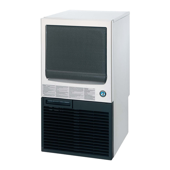
Hoshizaki KM-40B Service Manual
Self-contained crescent cuber
Hide thumbs
Also See for KM-40B:
- Instruction manual (8 pages) ,
- Instruction manual (13 pages) ,
- How to replace (13 pages)

Related Manuals for Hoshizaki KM-40B


Summary of Contents for Hoshizaki KM-40B
- Page 1 SELF-CONTAINED CRESCENT CUBER KM-40B KM-55B KM-80B SERVICE MANUAL F120-1011 (073117)
-
Page 2: Table Of Contents
6. SWITCHES ---------------------------------------------------------------------------------------- 30 III. TECHNICAL INFORMATION -------------------------------------------------------------------- 31 1. WATER CIRCUIT AND REFRIGERANT CIRCUIT --------------------------------------- 31 [a] KM-40B, KM-55B ----------------------------------------------------------------------------- 31 [b] KM-80B ----------------------------------------------------------------------------------------- 32 2. WIRING DIAGRAM ------------------------------------------------------------------------------ 33 [a] KM-40B (Philippines) ------------------------------------------------------------------------ 33 [b] KM-40B (Except Philippines), KM-55B ------------------------------------------------- 33... - Page 3 [c] KM-80B ----------------------------------------------------------------------------------------- 34 3. TIMING CHART ----------------------------------------------------------------------------------- 35 [a] KM-40B, KM-55B, KM-80B ---------------------------------------------------------------- 35 IV. SERVICE DIAGNOSIS ---------------------------------------------------------------------------- 36 1. 10-MINUTE DIAGNOSTIC PROCEDURE ------------------------------------------------- 36 2. NO ICE PRODUCTION ------------------------------------------------------------------------- 38 3. EVAPORATOR IS FROZEN UP -------------------------------------------------------------- 41 4. LOW ICE PRODUCTION ----------------------------------------------------------------------- 42 5.
- Page 4 [a] CLEANING PROCEDURE ----------------------------------------------------------------- 70 [b] SANITIZING PROCEDURE --------------------------------------------------------------- 73 2. MAINTENANCE ---------------------------------------------------------------------------------- 73 [a] EXTERIOR PANELS ------------------------------------------------------------------------ 73 [b] STORAGE BIN AND SCOOP ------------------------------------------------------------- 74 [c] AIR FILTER ------------------------------------------------------------------------------------ 74 [d] CONDENSER --------------------------------------------------------------------------------- 74 3. PREPARING THE ICEMAKER FOR LONG STORAGE -------------------------------- 74...
-
Page 5: Specifications
I. SPECIFICATIONS 1. DIMENSIONS/SPECIFICATIONS [a] KM-40B (Europe) -
Page 6: [B] Km-40B (Singapore)
[b] KM-40B (Singapore) -
Page 7: [C] Km-40B (Australia, New Zealand)
[c] KM-40B (Australia, New Zealand) -
Page 8: [D] Km-40B (Philippines)
[d] KM-40B (Philippines) -
Page 9: [E] Km-55B (Europe)
[e] KM-55B (Europe) -
Page 10: [F] Km-55B (Singapore)
[f] KM-55B (Singapore) -
Page 11: [G] Km-55B (Australia, New Zealand)
[g] KM-55B (Australia, New Zealand) -
Page 12: [H] Km-55B (Philippines)
[h] KM-55B (Philippines) -
Page 13: [I] Km-80B (Europe)
[i] KM-80B (Europe) -
Page 14: [J] Km-80B (Singapore)
[j] KM-80B (Singapore) -
Page 15: [K] Km-80B (Australia, New Zealand)
[k] KM-80B (Australia, New Zealand) -
Page 16: [L] Km-80B (Philippines)
[l] KM-80B (Philippines) -
Page 17: General Information
II. GENERAL INFORMATION 1. CONSTRUCTION [a] KM-40B, KM-55B Top Panel Separator Spray Tube Evaporator Door Water Supply Tube Front Panel Tank Louver Control Box Control Switch Condenser Hot Gas Valve Air Filter Fan Motor Front View Thermistor Water Valve Rear Panel... -
Page 18: [B] Km-80B
[b] KM-80B Top Panel Separator Spray Tube Evaporator Door Water Supply Tube Front Panel Tank Louver Control Box Control Switch Condenser Hot Gas Valve Air Filter Fan Motor Compressor Front View Thermistor Water Valve Rear Panel Pump Motor Pipe Cover Power Supply Cord Drain Valve... -
Page 19: [C] Icemaking Compartment
[c] ICEMAKING COMPARTMENT Water Valve Spray Tube Water Supply Pipe Evaporator Pump Motor Separator Cube Guide Float Switch Water Tank... -
Page 20: Sequence Of Operation
2. SEQUENCE OF OPERATION The steps in the sequence are as outlined below. When power is supplied, a 5 second delay occurs at startup. Note that the order of the LEDs from the outer edge of the board is 5, 6, 8, 4, 7. [a] ONE MINUTE FILL CYCLE LED 8 is on. -
Page 21: [E] Normal Harvest Cycle
occurs on the 2nd harvest after startup. Then, depending on the control board setting, drain cycle occurs every cycle, or every 2nd, 5th, or 10th cycle (S1 dip switch 5 & 6). [e] NORMAL HARVEST CYCLE LEDs 5, 6, and 8 are on. Comp continues to run, HGV remains open and WV opens. As the evaporator warms, the thermistor reaches 9°C. -
Page 23: Controal Board
3. CONTROL BOARD * A HOSHIZAKI exclusive solid-state control is employed in KM-40B, KM-55B, and KM- 80B Crescent Cubers. * All models are pretested and factory-adjusted. CAUTION 1. Fragile, handle very carefully. 2. A control board contains integrated circuits, which are susceptible to failure due to static discharge. -
Page 24: [A] Control Board Layout
[a] CONTROL BOARD LAYOUT "H" Control Board Relay LEDs (5) Connector K7 (indicate which relays Transformer are energized as listed below) LED 5 (X1 Relay) Compressor LED 6 (X2 Relay) Connector K3 Hot Gas Valve Magnetic Contactor Fan Motor (Fan Motor off when LED on) Connector K4 Open... -
Page 25: [B] Features
[b] FEATURES a) Maximum Water Supply Period - 6 minutes The inlet water valve will be open during harvest for 6 minutes or the length of harvest minus 0, 10, 30, or 50 seconds (adjustable by S1 dip switch 7 & 8), whichever is shorter. b) Harvest Backup Timer and Freeze Timer The harvest backup timer shuts down the icemaker if, for two cycles in a row, the harvest cycle takes more than 20 minutes to complete. - Page 26 The icemaker also automatically stops in cases of insufficient voltage (184Vac ±5% or less). The control board will signal this problem using 6 beeps every 3 seconds. When the proper supply voltage is resumed, the icemaker automatically starts running again. f) LED Lights and Audible Alarm Safeties The control board includes LED indicator lights, audible alarm safeties, and an output test feature.
-
Page 27: [C] Controls And Adjustments
WV–inlet water valve [c] CONTROLS AND ADJUSTMENTS a) Default Dip Switch Settings The dip switch is factory-adjusted to the following positions: S1 Dip Switch No. KM-40B KM-40B (Philippines) OFF KM-55B KM-55B (Philippines) KM-80B KM-80B (Philippines) OFF S2 Dip Switch No. - Page 28 b) Harvest Timer (S1 dip switch 1 & 2) Used for adjustment of the harvest timer. The harvest timer starts counting when the thermistor reads a certain temperature at the evaporator outlet. Dip Switch Setting Time No. 1 No. 2 (seconds) c) Drain Timer (S1 dip switch 3 &...
- Page 29 Dip Switch Setting Frequency No. 5 No. 6 every cycle every 2 cycles every 5 cycles every 10 cycles e) Water Saver Timer (S1 dip switch 7 & 8) The water saver timer allows the water valve to close and the pump motor to circulate water in the tank during the final part of harvest.
- Page 30 Refill Counter (S2 dip switch 3) Do not adjust. This must be left in the factory default position or the unit will not operate properly. The KM-40B, KM-55B, and KM-80B do not refill. j) Harvest Completion Detection Control (S2 dip switch 4) Do not adjust.
-
Page 31: [D] Control Board Check Procedure
Do not adjust. This must be left in the factory default position or the unit will not operate properly. It is deactivated on the KM-40B, KM-55B, and KM-80B. When activated, the thermistor detects the temperature of the evaporator outlet to find overfreeze in a harvest cycle and at the beginning of a freeze cycle. -
Page 32: [E] Control Board Replacement
1) Check the dip switch settings to assure that S1 dip switch 3, 4, 7, 8, 9, & 10 and S2 dip switch 1 through 6 are in the factory default position. S1 dip switch 1, 2, 5, & 6 are cleaning adjustments and the settings are flexible. -
Page 33: Bin Control Switch
4) Check for resistance between the thermistor leads. Normal reading is within 3.5 to 7 kΩ. Replace the thermistor if it exceeds the normal reading. 5. BIN CONTROL This machine uses a lever-actuated proximity switch (mechanical bin control) to control the ice level in the storage bin. -
Page 34: Switches
5) Disconnect the bin control at the 2-pin connector attached to the black wires coming from the K1 connector (pins 4 & 5) on the control board. 6) Check for continuity across the bin control leads. When calling for ice, the bin control proximity switch should be closed. -
Page 35: Technical Information
III. TECHNICAL INFORMATION 1. WATER CIRCUIT AND REFRIGERANT CIRCUIT [a] KM-40B, KM-55B Water Inlet Capillary Tube Accumulator Water Valve Spray Tube Thermistor Pump Motor Evaporator Water Tank Float Switch Drain Valve Drain Outlet Hot Gas Drier Valve Condenser Compressor Water Circuit... -
Page 36: [B] Km-80B
[b] KM-80B Water Inlet Water Valve Expansion Valve Spray Tube Thermistor Evaporator Water Tank Pump Motor Float Switch Drain Valve Drain Outlet Hot Gas Valve Compressor Drier Condenser Water Circuit Refrigeration Circuit... -
Page 37: Wiring Diagram
2. WIRING DIAGRAM [a] KM-40B (Philippines) [b] KM-40B (Except Philippines), KM-55B... -
Page 38: [C] Km-80B
[c] KM-80B... -
Page 40: Service Diagnosis
IV. SERVICE DIAGNOSIS 1. 10-MINUTE DIAGNOSTIC PROCEDURE The 10 minute check out procedure is basically a sequence check which can be used at unit start-up or for system diagnosis. Using this check out procedure will allow you to diagnose electrical system and component failures in approximately 10 minutes under normal operating conditions of 21°C or warmer air and 10°C or warmer water temperatures. - Page 41 starts after the thermistor temperature reaches 2°C. After this period, the freeze cycle operation is transferred to the float switch for freeze termination. During the first 5 minutes of freeze, confirm that the evaporator temperature drops. After the minimum freeze period, disconnect the float switch at the 2-pin connector attached to the red wires.
-
Page 42: No Ice Production
2. NO ICE PRODUCTION PROBLEM POSSIBLE CAUSE REMEDY [1] The icemaker a) Power Supply 1. OFF position. 1. Move to ON position. will not start. 2. Loose connections. 2. Tighten. 3. Bad contacts. 3. Check for continuity and replace. 4. Voltage too high. 4. - Page 43 PROBLEM POSSIBLE CAUSE REMEDY [2] Water a) Float Switch 1. Connector 1. Reconnect. continues to disconnected. be supplied, 2. Leads opened or 2. Check and replace. and the defective switch. icemaker will 3. Float does not move 3. Clean or replace. not start.
- Page 44 PROBLEM POSSIBLE CAUSE REMEDY [5] No water a) Water Supply 1. Water pressure too low 1. Check and get comes from Line and water level in Water recommended pressure. Spray Tubes. Tank too low. Water Pump b) Inlet Water Valve 1.
-
Page 45: Evaporator Is Frozen Up
3. EVAPORATOR IS FROZEN UP PROBLEM POSSIBLE CAUSE REMEDY [1] Freeze cycle a) Float Switch 1. Leads shorted or 1. Check and replace. time is too defective switch. long. 2. Float does not move 2. Clean or replace. freely. b) Inlet Water Valve 1. -
Page 46: Low Ice Production
4. LOW ICE PRODUCTION PROBLEM POSSIBLE CAUSE REMEDY [1] Freeze cycle a) See chart 1 - [3] and check dirty Air Filter or Condenser, ambient or water time is long. temperature, water pressure, and refrigerant charge. b) See chart 2 - [1] and check Float Switch, Water Solenoid Valve, and Control Board. -
Page 47: Other
6. OTHER PROBLEM POSSIBLE CAUSE REMEDY [1] Icemaker will a) Bin Control 1. Completely 1. Place in position. not stop when Switch disconnected and bin is filled dropped inside bin. with ice. 2. Detector broken. 2. Replace. 3. Detector out of position. 3. -
Page 48: Removal And Replacement
V. REMOVAL AND REPLACEMENT 1. SERVICE FOR REFRIGERANT LINES [a] SERVICE INFORMATION 1) Allowable Compressor Opening Time and Prevention of Lubricant Mixture [R134a] The compressor must not be opened more than 30 minutes in replacement or service. Do not mix lubricants of different compressors even if both are charged with the same refrigerant, except when they use the same lubricant. -
Page 49: [B] Refrigerant Recovery
7) Evacuation, Vacuum Pump and Refrigerant Charge [R134a] Never allow the oil in the vacuum pump to flow backward. The vacuum level and vacuum pump may be the same as those for the current refrigerants. However, the rubber hose and gauge manifold to be used for evacuation and refrigerant charge should be exclusively for R134a. -
Page 50: Brazing
8) Repeat steps 4) through 7), if necessary, until the required amount of refrigerant has entered the system. 9) Close the Refrigerant Access Valve, and disconnect the Hoses, Service Manifold, etc. 10) Cap the Access Valve to prevent possible leak. Depressed Access Valve OPEN... -
Page 51: Compressor
3. COMPRESSOR WARNING The Compressor Terminal Cover must be refitted in its correct position. Otherwise, operation under high temperature and high humidity conditions may cause electric shock, fire, or corrosion to shorten the service life. IMPORTANT Always install a new Drier every time the sealed refrigeration system is opened. -
Page 52: Drier
17) Refit the Louver and Rear Cover in their correct positions. 18) Plug in the icemaker or connect the power source. Note: Hoshizaki recommends that Compressor starting electrics are always replaced at the same time as the Compressor. 4. DRIER... -
Page 53: Hot Gas Valve
5. HOT GAS VALVE CAUTION To ensure optimum performance, use a copper tube of the same diameter and length for replacement of the hot gas circuit. IMPORTANT Always install a new Drier every time the sealed refrigeration system is opened. Do not replace the Drier until after all other repair or replacement has been made. - Page 54 7) Braze the new Hot Gas Valve with nitrogen gas flowing at a pressure of 0.2 - 0.3 bar. WARNING Always protect the valve body by using a damp cloth to prevent the valve from overheating. Do not braze with the valve body exceeding 135°C. 8) Install the new Drier (see “V.
-
Page 55: Expansion Valve - Km-80B Only
6. EXPANSION VALVE - KM-80B ONLY IMPORTANT The water in the refrigeration circuit may exceed the capacity of the Drier and freeze in the Expansion Valve. Always install a new Drier every time the sealed refrigeration system is opened. Do not replace the Drier until after all other repair or replacement has been made. - Page 56 Top Rear View with Top and Rear Panels Removed Remove Expansion Valve Cover first Cut ties to make Bulb removable Bulb Insulation Hose Wrap this part with a damp cloth to prevent Expansion Valve overheating Expansion Valve is brazed at these two points.
-
Page 57: Fan Motor
7. FAN MOTOR 1) Unplug the icemaker or disconnect the power source. 2) Remove the Louver. 3) Disconnect the Connector of the Fan Motor lead. 4) Remove the two screws securing the Fan Motor Bracket and pull out the Fan Motor in the arrow direction. -
Page 58: Pump Motor
8. PUMP MOTOR 1) Unplug the icemaker or disconnect the power source. 2) Remove the Top Panel and unscrew the Rear Panel. 3) Disconnect the Connector of the Pump Motor lead. 4) Remove the Water Tank (see “V. 15. WATER TANK”). 5) Remove the ties connecting the Pump Motor discharge outlet and pull off the Silicone Hose. -
Page 59: Water Valve
9. WATER VALVE 1) Unplug the icemaker or disconnect the power source. 2) Close the water supply tap. 3) Remove the Top Panel and unscrew the Rear Panel. 4) Disconnect the Tab Terminals. 5) Pinch and lower the Hose Clamp. 6) Disconnect the Rubber Hose from the Water Valve. -
Page 60: Drain Valve
10. DRAIN VALVE 1) Unplug the icemaker or disconnect the power source. 2) Close the water supply tap. 3) Drain the Water Tank (see “V. 15. WATER TANK”). 4) Disconnect any rigid (fixed) pipe for water supply and drain connections. 5) Unscrew the Rear Cover. -
Page 61: Float Switch
11. FLOAT SWITCH [a] KM-40B, KM-55B 1) Unplug the icemaker or disconnect the power source. 2) Remove the Top Panel and unscrew the Rear Panel. 3) Disconnect the Connector of the Float Switch lead and remove the lead wire from the Grommet through the slit. -
Page 62: [B] Km-80B
[b] KM-80B 1) Unplug the icemaker or disconnect the power source. 2) Remove the Top Panel and unscrew the Rear Panel. 3) Disconnect the Connector of the Float Switch lead (gray). 4) The Float Switch is located behind the Pump Motor. Pinch the arrowed part (1) and pull it diagonally forward (2) to unhook the Float Switch. -
Page 63: Bin Control Switch
7) Put the Float Switch down into the mounting hole and hook it in position as shown. To ensure proper operation, be sure to fit the Hook (A) under the mounting hole. 8) Refit the removed parts in the reverse order of the removal procedure. 9) Plug in the icemaker or connect the power source. - Page 64 Slide Rail [both sides] Pull Stopper (A) [both sides] Fig. 16 7) The Bin Control Switch (KM-40B) pulled out of the Storage Bin has the internal structure as shown below. Reed Switch Lead Hook Stopper (B) [both sides] * Fit in Stopper (A)
- Page 65 8) To remove the Bin Switch Plate, slightly warp both sides and pull the Shaft toward you. Slightly warp Top View Pull toward you Fig. 18 9) Refit the removed parts in the reverse order of the removal procedure. Be sure to put the lead wire back in the Retainer on the Bracket.
-
Page 66: Thermistor
13. THERMISTOR 1) Unplug the icemaker or disconnect the power source. 2) Remove the Top Panel and unscrew the Rear Panel. 3) Disconnect the Connector of the Thermistor lead (orange). 4) Remove the Ties, Insulation, Thermistor Holder, and Thermistor in this order. 5) Remove the old sealant from the Thermistor Holder and Suction Pipe. -
Page 67: Control Box
14. CONTROL BOX 1) Unplug the icemaker or disconnect the power source. 2) Remove the Louver. 3) Tilt the Tabs inward at the same time on both sides of the Control Box and pull the Control Box toward you. Tilting only one Tab will not work. 4) To refit the Control Box, push it in horizontally. -
Page 68: [A] Power Switch
Note: After replacing the components inside the Control Box, connect and tie the wires properly in their correct position. Especially make sure that the Harness does not press the Push Buttons on the Control Board. [a] POWER SWITCH 1) Disconnect the Tab Terminals and remove the Nut securing the Power Switch. 2) Install the new Switch in the reverse order of the removal procedure. -
Page 69: [F] Compressor Capacitor - Km-80B Only
2) Install the new Relay in the reverse order of the removal procedure. 3) To prevent miswiring, check the terminal numbers and lead wire colors with the Wiring Label. [f] COMPRESSOR CAPACITOR - KM-80B ONLY 1) Disconnect the Tab Terminals and cut the Tie. 2) Install the new Capacitor in the reverse order of the removal procedure. - Page 70 3) Pinch and push down the Snaps on both sides of the Bracket to unhook the Water Tank from the square holes, and pull it about 1” toward you. Snap Water Tank Fig. 22 4) When the Snaps are unhooked from the square holes, the rear part of the Water Tank (dotted circle below) is also unhooked.
-
Page 71: Cube Guide
6) Slide the left side of the Water Tank to release it from the Bracket Rail, lift down the entire Water Tank, and pull it toward you out of the Storage Bin. Do not hit the other components. 7) Refit the Water Tank in the reverse order Bracket Rail of the removal procedure (left, right, top, rear). -
Page 72: Separator
17. SEPARATOR 1) Unplug the icemaker or disconnect the power source. 2) Remove the screws at the rear and take off the Top Panel. 3) Hold both sides of the Separator from the top. Bend the Front Separator into a U-shape and remove it from the Shaft of the Evaporator Bracket. -
Page 73: Door
5) The Water Supply Pipe is located right under the Spray Tube. Remove the Water Supply Pipe from the Evaporator, pinch and shift the Hose Clamp, and disconnect the Hose. 6) The Spray Guide is located under the Water Supply Pipe. Pull off the Spray Guide from the Evaporator Plate. -
Page 74: Cleaning And Maintenance Instructions
[a] CLEANING PROCEDURE 1) Dilute 148 ml of recommended cleaner Hoshizaki “Scale Away” with 3.8 lit. of water. 2) Remove the air filter. Remove all ice from the evaporator and the ice storage bin. Note: To remove cubes on the evaporator, move the control switch to the “OFF”... - Page 75 They are snapped in place. See Fig. 30. 15) Dilute 148 ml of recommended cleaner Hoshizaki “Scale Away” with 3.8 lit. of water. 16) Wash the bin control switch, water tank, float switch, cube guide, silicone hose and overflow pipe by using a nylon scouring pad, brushes and the cleaning solution.
- Page 76 KM-80B (behind the pump motor). Cube Guide Water Tank Fig. 29 Cube Guide Water Tank Snap * This illustration shows KM-40B. The following number of cube guides are provided: KM-40B 2 pcs KM-55B 3 pcs KM-80B 3 pcs * The bin control switch is accessible by removing the water tank.
-
Page 77: [B] Sanitizing Procedure
[b] SANITIZING PROCEDURE - Following Cleaning Procedure 1) Dilute approximately 9.2 ml of an 8.25% sodium hypochlorite solution (chlorine bleach) with 3.8 lit. of warm water. Using a chlorine test strip or other method, confirm that you have a concentration of about 200 ppm. 2) Soak the removed parts from step 16 above in a clean container containing the sanitizing solution. -
Page 78: [B] Storage Bin And Scoop
[b] STORAGE BIN AND SCOOP * Wash your hands before removing ice. Use the plastic scoop provided (Accessory). * The Storage Bin is for ice use only. Do not store anything else in the bin. * Keep the scoop clean. Clean it by using a neutral cleaner and rinse thoroughly. * Clean the bin liner by using a neutral cleaner. - Page 79 [a] Remove the water from the potable water supply line: 1) Remove the Air Filter if it has not already been removed. 2) Move the Control Switch on the Control Box to the “OFF” position. 3) Unplug the icemaker or disconnect the power supply. 4) Close the water supply tap, and remove the Inlet Hose.