Table of Contents
Advertisement
Quick Links
Advertisement
Table of Contents
Troubleshooting

Related Manuals for Smart Technologies SMART Board 4000i


Summary of Contents for Smart Technologies SMART Board 4000i
- Page 1 Installation Guide SMART Board 4000i Interactive Whiteboard...
-
Page 2: Technical Support
Trademark Notice SMART Board, DViT, X-Port, Notebook and the SMART logo are trademarks of SMART Technologies Inc. EPSON and PowerLite are registered trademarks of Seiko Epson Corporation, registered in the U.S. and other countries. Windows is a registered trademark or a trademark of Microsoft Corporation in the U.S. -
Page 3: Important Information
Important Information Please read this manual carefully before setting up and using the Rear Projection SMART Board 4000i interactive whiteboard. With proper care, your 4000i should provide years of trouble-free service. WARNING The projector inside the cabinet is a high-brightness light source. Do not stare into this beam of light or view it directly. - Page 4 Si vous avez des doutes sur le type de système d’alimentation disponible lors de l’installation de votre 4000i, contactez un personnel qualifié. La 4000i sólo se podrá utilizar con los sistemas eléctricos TN y TT europeos. Este modelo no está disponible para antiguos sistemas eléctricos de tipo IT que aún se utilizan en algunos países europeos.
-
Page 5: Other Warnings And Safety Precautions
• Avoid setting up and using the 4000i in an area with excessive levels of dust, humidity or cigarette smoke, or where it’s exposed to extreme heat or cold. The operating temperature range is from 41°F to 85°F (5°C to 29°C) with up to 80% humidity (non- condensing). - Page 6 • The projector that comes with the 4000i includes a lamp component that contains mercury. If you replace the lamp, don’t put the old one in the trash. Instead, consult the regulations for properly and safely disposing of it in your area.
-
Page 7: Table Of Contents
Other Warnings and Safety Precautions ... iii List of Figures ... vii List of Tables ... viii Getting to Know the 4000i ... 1 The Pen Tray and the Control Panel ... 3 Storage Options ... 4 The Connection Panel ... 5 The Power and Laptop Umbilical Connections ... - Page 8 Appendix A: Disassembling and Reassembling the Cabinet ... 61 Disassembling the Cabinet ... 61 Reassembling the Cabinet ... 68 Appendix B: Understanding the Cabling in the 4000i ... 75 Customer Support ... 79 Contacting SMART Technical Support ... 79 General Inquiries ... 79 Returning Defective Merchandise ...
-
Page 9: List Of Figures
List of Figures The Major Components of the 4000i ... 2 The Pen Tray and the Control Panel ... 3 The Storage Features of the 4000i ... 4 The Connection Panel ... 5 The Power and Laptop Connections ... 6 The Location of the Guest Laptop Shelf and J-Hook ... - Page 10 List of Tables States of the Projector ... 7 Startup Scenarios ... 42 Switching Sources with the 4000i ... 45 Interpreting the Lamp Status LED ... 58 Troubleshooting Image Problems ... 59 Troubleshooting Remote Control and the USB Cable Problems ... 59 Troubleshooting Touch and Control Problems ...
-
Page 11: Getting To Know The 4000I
This guide includes instructions on setting up (page 8), finalizing (page 32), using (page 41) and maintaining (page 49) the 4000i. You can also use this guide if you need to disassemble and then reassemble the cabinet (page 61) or if you want to learn about the internal wiring and cables of the unit (page 75). -
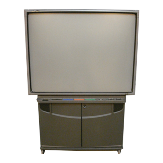
Page 12: The Major Components Of The 4000I
Interactive Screen Speakers (x2) Manual Pocket You can purchase optional components for the 4000i, such as a videoconferencing shelf to house your videoconferencing camera, and a room control module to integrate the 4000i with a room control system. Lockable Doors... -
Page 13: The Pen Tray And The Control Panel
You can customize any of these tools with SMART Board software. NOTE: The 4000i comes with styluses that have black tips, which are better detected by the digital cameras than any other kind of stylus. If you need to purchase a different stylus, choose one that has a dark tip. -
Page 14: Storage Options
Storage Options The 4000i houses the projector in the middle of the cabinet. You can house your internal computer on the right side of the projector, and use the other side for another compact device. Your 4000i also comes with: •... -
Page 15: The Connection Panel
RJ45 network port (2) for connecting the internal computer to a room network outlet (see page 22) • a 15-pin (female) RGB video port (3), for connecting an external projector or monitor (RGB output only) that allows you to display the video externally (see page 30) •... -
Page 16: The Power And Laptop Umbilical Connections
The Power and Laptop Umbilical Connections The power connections are at the back of the 4000i, beside the connection panel. Here, you can connect: • the Main Power IN cable (with the country-specific cable), to supply power to the 4000i (see page 31) •... -
Page 17: The Epson 9300I Projector
The Epson 9300i Projector The 4000i comes with an Epson 9300i multimedia projector for you to install in the cabinet. This projector has been selected for its high resolution and its uniform brightness and clarity. Also, its lamp has a life expectancy of 7,000 hours. -
Page 18: Setting Up The 4000I
When the 4000i is in this location, lock the casters by pressing the caster tab locks on the wheel. If you need to unlock the casters, press the other side of this tab. -
Page 19: Installing The Laptop Shelf
3. Push the captive thumbscrew at the bottom of the shelf into the thumbscrew hole and tighten. Setting Up the 4000i One Location for the J-hook One Location for the Guest Laptop Shelf NOTE: The IR receiver isn’t shown in this illustration. -
Page 20: Installing The Optional Videoconferencing Shelf
The mounting arm of the shelf provides a convenient hidden channel for the camera cabling. J-hook Mounting Arm Figure 7: The Installed Videoconferencing Shelf Setting Up the 4000i NOTE: For clarity, this illustration doesn’t show the guest laptop shelf. - Page 21 3. Remove the caps and plug from the mounting arm at the location where you want to mount the shelf. Feed the cables for the videoconferencing camera through the large hole, down the channel and out through the lower mounting point. Setting Up the 4000i NOTE: The cables shown in this illustration may not match your...
- Page 22 1/4-20 x 1/2" fasteners (removed in step 1) to secure the mounting arm to the cabinet. When you do this, you replace the safety screw, so you can now safely move the cabinet. NOTE: For clarity, this illustration doesn’t show the cables. Setting Up the 4000i...
- Page 23 8. You can use the J-hook to manage the cables along the side of the cabinet. If you haven’t already installed the J-hook, clip it to the handle on the side of the 4000i. Then route the cables through it to the connection panel at the rear of the cabinet.
-
Page 24: Removing The Rear Access Panel
Removing the Rear Access Panel You must remove the rear access panel before you can install devices inside the cabinet, such as the internal computer and the projector. After you install these devices, replace the rear access panel to keep your equipment secure. -
Page 25: Installing The Projector
Installing the Projector To install the projector, attach the mounting bracket to the cabinet, attach the projector to the mounting bracket, connect the cable extensions, and finally angle the projector towards the large mirror inside the cabinet. When you unpack your projector, you should keep the box and packing material in case you ever need to transport the projector. - Page 26 4. From the back of the 4000i (with the rear access panel removed), put the mounting bracket on the bottom of the cabinet. When you do this, rest the arms of the mount on the floor behind the 4000i. 5. Align the holes in the clamps with the holes on the bottom of the cabinet and insert two of the 1/4-20 hex socket screws from the accessory kit into these holes.
- Page 27 7. Set the projector on the flat plate of the mounting bracket with the four protruding screws on the bottom of the projector slipping through the large part of the keyhole slots in the plate. Also ensure that the slots on the bottom of the projector fit around the tabs on the plate.
- Page 28 When you complete this step, your unit will look like this: 9. Locate the projector cable bundle that’s on the left side of the cabinet (when you’re facing the front of the unit) and connect: – the 15-pin male connector of the RGB video cable labeled RGB2 to the projector port labeled Computer 2 –...
- Page 29 10. Connect the power cable labeled Projector AC to the projector’s Power port. The other end should be connected to the power bar inside the 4000i. Power Port 11. With the projector attached to the mounting bracket, gently tilt the mounting bracket up so that the threaded inserts on the arms align with the holes in the underside of the connection panel bracket.
- Page 30 13. Tighten the screws that hold the mounting bracket to the cabinet using the 3/16" hex key. (You inserted these in step 5.) Tighten these screws 14. Slightly tighten the projector screws that protrude through the keyholes in the mounting bracket. To do this, use the M4 hex key from the accessory kit. Screws...
- Page 31 M4 hex key. 17. Remove the lens cap from the projector. 18. Check that the cables that are connected to the projector have no sharp bends or stress points in the final position. 19. Route the cable bundles along the sides of the projector mount and snap the releasable tie wraps into the three holes on the mounting bracket.
-
Page 32: Installing The Internal Computer
4000i from room to room. These straps won’t secure the computer during cabinet shipment, so if you need to transport the 4000i, remove the computer before you ship it. -
Page 33: Connecting A Guest Laptop
Computer 2 Serial (Female) Figure 10: The Laptop Umbilical Cable Connectors The 4000i includes a serial connection for the laptop, but you can supply a USB connection by connecting the SMART USB adapter from the accessory kit to the Computer 2 Serial cable, as shown in Figure 11. -
Page 34: Connecting The Smart Usb Adapter To A Guest Laptop
Figure 11: Connecting the SMART USB Adapter to a Guest Laptop The 4000i comes with the umbilical cables already connected to the connection panel. However, if your cables become detached from the panel, see page 53 for instructions on reconnecting them. For details on using the guest laptop and troubleshooting image problems, see page 46. -
Page 35: Connecting A Vcr Or Dvd Player (Optional)
If your third video source is connected to the 4000i with an S-video cable, you can view it on the interactive whiteboard by pressing the Display Source button until the LED beside the third video source is lit. -
Page 36: Connecting A Vcr Or Dvd Player
2. Connect the other end of the DVI cable to the projector. Read the Epson 9300i Multimedia Projector User’s Guide for details on the type of DVI cable that you must use and how to connect the device to the projector. Printer / Network... -
Page 37: Connecting A Printer To The Internal Computer (Optional)
You can connect a standard DB25 printer cable (not provided) from the printer’s parallel port to the Printer port on the connection panel. This makes the printer available for the internal computer only. The 4000i doesn’t switch control of the printer, so you can’t access it with a guest laptop. -
Page 38: Connecting The Internal Computer To A Network
To connect the laptop umbilical cable to a network outlet, see Figure 12 on page 24. To Network Wall Outlet Network IN Printer / Network Outputs Auxiliary Inputs S-Video S-Video Computer 2 Inputs Figure 15: Connecting to a Network Outlet Setting Up the 4000i RJ45 Network Cable... -
Page 39: Connecting An External Sound System (Optional)
Connecting an External Sound System (Optional) The sound from your selected input source goes into the 4000i’s audio board where the signal is amplified sufficiently for the levels needed by the internal speakers. However, to send the audio signal to an external, unbalanced sound system, connect standard RCA audio cables to the audio Outputs on the connection panel. -
Page 40: Connecting An External Monitor Or Projector (Optional)
Connecting an External Monitor or Projector (Optional) You can send the video signal to another RGB video source, such as an external projector or a monitor. To do this, connect a 15-pin male video cable (not provided) from the external projector or monitor to the 15-pin female video Outputs port on the connection panel. -
Page 41: Powering Up The 4000I
Powering up the 4000i When you’ve connected all your devices to the 4000i, you’re ready to connect the main power cable and power up the internal computer and the projector. After you do this, you must finalize your installation, as described in the next section (page 32). -
Page 42: Finalizing The Installation
(if necessary) (page 40) After you’ve made these adjustments and configurations, your 4000i is ready for use. Read the section entitled Using the 4000i on page 41 for details on how to use the unit. Adjusting the Projected Image After you’ve installed your projector, you must make a few adjustments to ensure that the... - Page 43 4. After you’ve made these vertical adjustments, check the image on the interactive screen. You may need to turn the adjustment knob on the projector mount to make the image appear larger or smaller. Finalizing the Installation...
- Page 44 Lens Shift button on the projector’s remote control. NOTE: For clarity, this illustration shows the mounting bracket out of the 4000i. Also, no cables are shown. Don’t overtighten the lockdown bolt. This bolt only needs slight pressure to hold the plate in place.
-
Page 45: Customizing The A/V Mute Screen
4. Select Advanced 1 and press the Enter button. 5. If you want the image to display during the projector’s warm up period, select Startup Screen > On and then press the Enter button. -
Page 46: Configuring The Computer And Projector Settings
Of course, if you don’t want to keep the internal computer on, you can shut it down (and power it off, if necessary). In this case, the next time you use the 4000i, you must open the front door and turn on the computer. -
Page 47: Installing Smart Board Software
Recommended projector settings When you receive the 4000i, the projector settings are optimized for you. However, if these settings are altered, you may need to reset them (see page 55). IMPORTANT Do not modify the following projector settings: • Standby Mode, which must be set to Network ON •... -
Page 48: Configuring The Interactive Whiteboard
If you install SMART Board software, but you don’t have touch control of the interactive screen, you must manually configure the computer port that’s connected to the 4000i. This involves specifying which serial or USB port on the internal computer is connected to the interactive whiteboard. -
Page 49: Orienting The Interactive Whiteboard
Orienting the Interactive Whiteboard To accurately respond to a finger or pen tray tool touch, the computer needs to know the exact location of the projected image on the screen. You give the computer this information when you orient the interactive whiteboard. Orienting is a very simple process of precisely touching a grid of red crosses. -
Page 50: Matching The Computer's Resolution To The Projector's Resolution
To make the most of the 4000i’s high resolution display, set the resolution setting of any computer used with the 4000i to the optimal resolution of the projector, which is 1400 x 1050 pixels. If the computer isn’t using this setting, the on-screen image may not properly fill the screen. -
Page 51: Using The 4000I
4000i and SMART Board software. Read this section of the guide for details that are specific to the 4000i, and read the SMART Board Software User’s Guide that came with your 4000i to understand the many features of SMART Board software. -
Page 52: Startup Scenarios
You can see this projector may be experiencing LED when you open the front doors problems that interfere with of the 4000i. Read the Epson normal operations. PowerLite 9300i Multimedia Projector User's Manual for assistance. -
Page 53: Understanding The Control Panel Leds
You can adjust the volume for the active display source independently of all other sources. So you can configure the volume level for one source, change the display source, and configure a different level for the new source. The 4000i retains the levels that you set for each of the three input sources. -
Page 54: Adjusting The Projector Settings
You can adjust the brightness and contrast levels for each source independently of all other sources. The 4000i then saves your settings. For example, if you increase the brightness of the display from the VCR, the brightness for the computer’s display is unaffected. -
Page 55: Changing The Display Source
Other S-video source (DVD player or document camera) Table 3: Switching Sources with the 4000i If your Computer 1 source is connected with BNC connectors (not supplied), you can change Source 1 to the BNC setting by holding all three Down buttons for three seconds. To change Source 1 back to the 15-pin connector, hold the three Up buttons for three seconds. -
Page 56: Changing Video Display Sources
Video IN LED illuminates and then press the DVI Source button on the remote control. If you press the Display Source button, you reset the 4000i. ll no longer see the composite or DVI video image. To return to these video sources, you must repeat the process, including the remote control button press. -
Page 57: Using The Smart Board Interactive Whiteboard
If the image on the screen is too large or too small, check that the resolution setting for your laptop. The projector in the 4000i scales all resolutions from 640 x 480 pixels and up. However, not all resolutions are useable and the image quality suffers if you don’t use the optimal resolution of 1400 x 1050 pixels (see page 40). -
Page 58: Shutting Down The 4000I
If you prefer, you can also shut down the computer. However, we recommend logging off rather than shutting down the computer, because it makes it easier to turn the 4000i back on. (You just press the Projector Standby button.) For more details on the states of the projector, see page 7. -
Page 59: Maintaining And Troubleshooting The 4000I
Cleaning the Cabinet, the Mirror and the Interactive Whiteboard Periodically dust the mirror and outside of the cabinet using a soft cloth. To clean the mirror, remove the 4000i’s side panel (see page 64), and then use a standard, alcohol-free glass cleaner. -
Page 60: Cleaning The Projector
You should let the projector lamp cool for at least three minutes before you unplug the 4000i. Clean the projector casing with a soft, dry cloth. If it is heavily soiled, you can use a damp cloth and a mild detergent, but don’t use strong detergent, wax or a chemical solvent, such as alcohol, benzene or paint thinner. - Page 61 To remove the projector from the cabinet 1. Shut down the projector (see page 48) and unplug it when the lamp has cooled down. 2. Open the front doors of the 4000i and disconnect all cables that are connected to the projector, including the power cable.
- Page 62 10. Set the projector on a flat surface. Maintaining and Troubleshooting the 4000i To return the projector to the cabinet of the 4000i, follow the procedure on page 15. NOTE: For clarity, this illustration doesn’t show the side panel or any cables.
-
Page 63: Replacing The Projector Lamp And Air Filter
Connecting the Laptop Umbilical Cables to the Connection Panel When you receive the 4000i, the laptop umbilical cables are already connected to the connection panel. However, should these cables become detached and require reattachment, use these instructions and the following two illustrations. -
Page 64: The Laptop Umbilical Cables (Connection Panel End)
5. Connect the country-specific adapter to the AC Power cable, and then connect that cable to the Laptop Power OUT outlet, located to the right of the connection panel. Figure 25: Connecting the AC Power Cable from the Laptop Umbilical Maintaining and Troubleshooting the 4000i Computer 2 Network Computer 2 Audio... -
Page 65: Adjusting The Projector Settings
Adjusting the Projector Settings The projector is configured for optimal performance within the 4000i. However, if these settings are altered, you can easily restore them. IMPORTANT Do not modify the following settings: • Standby Mode, which must be set to Network ON •... -
Page 66: Adjusting The Front Doors
5. Swing the door shut. Step 3: Lift the door from the bottom Maintaining and Troubleshooting the 4000i Do not loosen the screws on the cabinet side of the hinge. Step 4: Push the door toward the cabinet... -
Page 67: Troubleshooting
Troubleshooting If you discover a problem with your 4000i, read the hints and tips in this section to isolate and resolve the problem. Most problems result from incorrect cabling, an incorrect computer setting or improperly installed or configured software, including the video card settings. Of course, for the 4000i to be working properly, its major components must be functioning correctly. -
Page 68: Interpreting The Lamp Status Led
LEDs, in a clockwise marquee pattern You can also use the three LEDs on the projector (Power, Lamp Status and Temperature) to interpret the status of the projector. Read the Epson PowerLite 9300i Multimedia Projector User’s Guide for information on interpreting these LEDs. -
Page 69: Troubleshooting Image Problems
SMART USB adapter doesn’t work properly Table 6: Troubleshooting Remote Control and the USB Cable Problems Maintaining and Troubleshooting the 4000i Possible Remedy Use the Lens Shift buttons on the projector to adjust the image position. Also see page 32 for information on adjusting the projector and the mounting bracket. -
Page 70: Troubleshooting Touch And Control Problems
You see gaps in the electronic ink when you write on the screen Table 7: Troubleshooting Touch and Control Problems Maintaining and Troubleshooting the 4000i Cause Possible Resolution Software Make sure SMART Board software is problem running. -
Page 71: Appendix A: Disassembling And Reassembling The Cabinet
If you are transporting the 4000i, you should remove the internal components, such as the projector and the computer, and repackage them in their original boxes. - Page 72 2. If you need better access to the cabinet, unlock the wheels by pressing the caster tab locks on each wheel and rolling the unit to a more convenient location. Press the caster tabs in the opposite direction to lock the wheels again. Unlock 3.
- Page 73 3. Feed the cables through the large hole in the mounting arm. 4. Remove the three hex socket screws (shown below, includes one safety screw) that hold the mounting arm to the cabinet using the 5/32" hex key from the 4000i’s accessory kit.
- Page 74 To remove the right side panel 1. Remove the two hex socket screws (shown below) using the 5/32" hex key from the accessory kit. Do not remove this screw IMPORTANT 2. Remove the two hex screws on the rear of the cabinet using the 5/32" hex key from the accessory kit.
- Page 75 3. With one hand grasping the panel’s side handle and the other hand on top, pull the side panel off the cabinet. Side Panel Side Handle To remove the interactive screen NOTE: This procedure requires two people. CAUTION Never touch the back of the screen or brush against it with your head. If you do smudge this surface, lightly spray alcohol-free glass cleaner onto a soft cloth and then lightly dab the affected area to remove the marks.
- Page 76 2. Loosen the four captive fasteners on the back corners of the interactive whiteboard using the Phillips No. 2 screwdriver from the accessory kit. Start with the two bottom fasteners and then loosen the top two (you may require a step stool to reach these fasteners).
-
Page 77: The Location Of The Safety Screw In The Handhold
To remove the top half of the cabinet IMPORTANT This procedure requires two people. 1. Using the 5/32" hex key from the accessory kit, remove the safety screw that’s located inside each side handle. With the screen removed, you’ll find it easiest to reach inside the cabinet and remove the screw through the hole above the handhold. -
Page 78: Reassembling The Cabinet
3. With you and your partner gripping a side handle with one hand and supporting the top of the cabinet with the other, carefully lift the top half of the cabinet off the base and place it on the floor. Reassembling the Cabinet To return the cabinet to its operating state, follow these procedures: •... - Page 79 3. Using the same hex key, replace a safety screw in each handle. To replace the interactive screen IMPORTANT This procedure requires two people. Never touch the back of the screen or brush against it with your head. CAUTION If you do smudge this surface, lightly spray alcohol-free glass cleaner onto a soft cloth and then lightly dab the affected area to remove the marks.
- Page 80 2. Tighten the four captive fasteners on the back corners of the interactive whiteboard using the Phillips No. 2 screwdriver from the accessory kit. Tighten the two bottom fasteners and then the top two. (You may need a step stool to reach the top two.) NOTE: As you tighten the screws, maintain constant pressure on the screwdriver to avoid damaging the screw heads.
- Page 81 To reinstall the side panel 1. Align the three tabs on the side panel with the slots in the cabinet and then slide the panel onto the cabinet. Side Panel 2. Reinsert the two screws on the rear of the cabinet using the 5/32" hex key. Rear Hex Screws Appendix A: Disassembling and Reassembling the Cabinet...
- Page 82 To reinstall the videoconferencing shelf 1. If you removed a mounting arm, as described on page 63, replace it and insert the three hex socket screws as shown below. Safety Screw 2. Feed the videoconferencing unit’s cables through the appropriate hole in the mounting arm.
- Page 83 To return the cabinet to its operating state 1. Replace the two hex socket screws shown below using the 5/32" hex key from the accessory kit. (If you’ve attached the videoconferencing mounting arm, you’ve already replaced one of these screws.) 2.
- Page 84 Press the caster tab locks in the opposite direction to lock the wheels again. Unlock 6. Reconnect the power cable to the power outlet, and turn on the computer and projector. Appendix A: Disassembling and Reassembling the Cabinet Guest Laptop Shelf Thumbscrew NOTE: The cables aren’t...
-
Page 85: Appendix B: Understanding The Cabling In The 4000I
Appendix B: Understanding the Cabling in the 4000i Wonderbar/ Control Panel RCA OUT RCA IN Controller Bundled Cable Appendix B: Understanding the Cabling in the 4000i PT10 PC 2 IN Figure 29: Cable Schematic... -
Page 86: Schematic Cable Summary
Serial Cable for Computer 2 Audio Cable for Computer 2 Power Cable for Computer 2 RGB Video Cable for Computer 2 Network Cable for Computer 2 Wireless Keyboard and Trackball Appendix B: Understanding the Cabling in the 4000i Table 8: Schematic Cable Summary... - Page 87 93-199 I²C MOD6 93-199 I²C MOD6 93-200 I²C MOD6 Appendix B: Understanding the Cabling in the 4000i Remarks From the Composite Video jack (via coupler) on the connection panel to the Composite Video jack on the projector From the Computer 1 to the projector’s Computer 1 port...
-
Page 88: Cable Summary
Temp Sensor circuit board Not Shown 30-438 Hook-and-loop straps 03-009 Wireless serial keyboard Appendix B: Understanding the Cabling in the 4000i Remarks Between the communications hub and the interactive screen Between Computer 2 and the X-Port unit From X-Port unit to the... -
Page 89: Customer Support
Fax: +1.403.806.1256 E-mail: support@smarttech.com Website: www.smarttech.com/support When you phone Technical Support, it will be helpful if you have access to your 4000i during the call. The support representative may ask you for the following information: • the serial number of the unit (which is on a sticker beside the connection panel on the back of the unit) •... -
Page 90: Returning Defective Merchandise
NOTE: After the warranty period, you are responsible for transporting the product to and from the service center. Registration A Registration card was included with your 4000i. To help us serve you, fill in and mail this card to SMART Technologies Inc. or register online at www.smarttech.com/registration. Sending Feedback You can help us improve our documentation by e-mailing your comments to TechnicalDocumentation@smarttech.com. -
Page 91: Index
Projector Air Filter Computer Installing SMART Board Software Power Settings Computer Resolution Configuring the SMART Board Interactive Whiteboard Connecting External Monitor or Projector External Sound System Guest Laptop Power Projector Cables Umbilical Cables VCR, DVD Player or Document Camera Connection Panel... - Page 92 VCR, DVD Player or Document Camera Videoconferencing Shelf Internal Computer Connecting Network Connection Printer Keystone Correction Laptop Connections to the 4000i Power Output see Guest Laptop Active Display Source Display Source Lamp Status Lamp Status States Third Video Source Troubleshooting...
- Page 93 Replacing the Projector Lamp and Filter Resetting the Projector Resolution Restarting Your System Reversible Standby Mode RGB, External Video Safety Precautions Screen Saver Setting Up Shutting Down 4000i Projector Side Panel Removal 61, 64 SMART Board Interactive Whiteboard Cleaning Configuring Orienting Removing Using...
- Page 94 Suite 300, 1207 11th Avenue SW Calgary, AB CANADA T3C 0M5 Main Switchboard: 1.888.42.SMART (Canada/U.S.) or +1.403.245.0333 (all other countries) Support Tel.: 1.866.518.6791 (Canada/U.S.) or +1.403.228.5940 (all other countries) Support Fax: +1.403.806.1256 support@smarttech.com www.smarttech.com 99-00582-00 REV A0...