Smart Technologies SMART Board 3000i Installation Manual
Rear projection
Hide thumbs
Also See for SMART Board 3000i:
- User manual (6 pages) ,
- Setup (6 pages) ,
- Specification sheet (3 pages)
Table of Contents
Advertisement
Quick Links
Advertisement
Table of Contents

Related Manuals for Smart Technologies SMART Board 3000i


Summary of Contents for Smart Technologies SMART Board 3000i
- Page 2 SMART Technologies Inc. Information in this manual is subject to change without notice and does not represent a commitment on the part of SMART.
-
Page 3: Important Information
Important Information Please read this manual carefully before setting up and using the Rear Projection SMART Board 3000i interactive whiteboard. With proper care, your 3000i should provide years of trouble-free service. WARNING The projector inside the 3000i cabinet is a high-brightness light source. Do not stare into the beam of light or view it directly. -
Page 4: Cleaning The Cabinet Components And Mirrors
Do not modify the power cord. 13 If you require replacement parts, ensure the service technician uses the replacement parts specified by SMART Technologies Inc. or parts with the same characteristics as the original. Cleaning the Cabinet Components and Mirrors Periodically dust mirrors and cabinet components using a soft cloth. -
Page 5: Cleaning The Projector
WARNING: Do not, under any circumstances, apply isopropyl alcohol, water or acetone to the rear surface of the interactive whiteboard screen. If any of these fluids come into contact with this surface, the diffusion coating could be damaged, resulting in a permanent deterioration in display quality. -
Page 6: Preventing Damage To The Writing Surface
Lamp Mode Two lamp modes are available: the default (and recommended) Normal mode (100% brightness) and Eco mode (80% brightness). Eco mode is dimmer than Normal mode, but offers increased lamp longevity and conserves power. Projector Power Put the projector into standby mode at the end of each session by pressing the Projector Standby button on the 3000i Control Panel. -
Page 7: Table Of Contents
Contents Important Information ................ i Cleaning the Cabinet Components and Mirrors ..........ii Cleaning the Projector ................... iii Preventing Damage to the Writing Surface ........... iv Introduction ..................1 3000i Features....................1 SMART Pen Tray Features ................3 Control Panel ....................4 Side Features ....................5 Rear Features....................6 Connection Panel ...................7 Main Power Input and Power Outputs ............8... - Page 8 Contents...
-
Page 9: Introduction
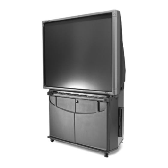
Introduction The 3000i is a slim Rear Projection SMART Board interactive whiteboard cabinet with an integrated LCD projector and a 67" (170.2 cm) diagonal interactive SMART Super Screen. (The Super Screen is an interactive whiteboard designed for enhanced rear-projection clarity.) To enable rear projection capability, a mirror system in the cabinet redirects the projected image from your computer, VCR, DVD player or guest laptop onto the back of the interactive whiteboard screen. -
Page 10: Getting To Know Your 3000I
Getting to Know Your 3000i Lockable Doors Lockable Casters (x 4) SMART Super Screen SMART Pen Tray Control Panel Laptop Shelf Manual Pocket Your Computer Projector Platform (with round-hole, rack-mounting rails) 3000i Installation Guide... -
Page 11: Smart Pen Tray Features
SMART Pen Tray Features Eraser Black Stylus Blue Stylus Red Stylus Green Stylus Pen Tray Buttons Using a Pen Tray Stylus Using the Pen Tray Buttons To write on top of the computer image, just Press the top Pen Tray button to make the pick up a stylus from the Pen Tray and SMART Keyboard appear for on-screen typing write on the interactive whiteboard. -
Page 12: Control Panel
Control Panel The Control Panel allows you to adjust major aspects of the visual display, as well as the volume of the internal (or a connected external) sound system. The volume settings for individual input sources are retained. In other words, if you set the audio level differently for each device, these settings are preserved when you switch back and forth among devices. -
Page 13: Side Features
Side Features Handle Guest Laptop Shelf Keyboard Holder Guest Laptop Shelf This shelf is specifically designed to support a guest laptop (or a VCR/DVD player). You can mount this shelf on either side of the cabinet. For instructions on installing the shelf, see page 10. Keyboard Holder This holder provides a convenient means of storing the wireless keyboard when it’s not in use. -
Page 14: Rear Features
Rear Features Printer / Network Outputs Auxiliary Inputs S-Video S-Video Computer 2 Inputs Computer 2 Computer 2 Serial Serial Closeup of Connection Panel 3000i Installation Guide... -
Page 15: Connection Panel
Connection Panel The Connection Panel allows you to make a variety of external connections to the 3000i cabinet: • A printer (1), dedicated to the internal computer • A network (2), making the full resources of the network available to the internal computer •... -
Page 16: Main Power Input And Power Outputs
Main Power Input and Power Outputs Located to the right of the Connection Panel (as you face the rear of the cabinet), the Main Power IN provides power to the projector, the internal computer, connected peripherals and the laptop. The Laptop Power OUT is used to provide power to a guest laptop via the Laptop Umbilical. The remaining Power OUTs are for the internal computer, projector, VCR or DVD, and printer. -
Page 17: Installation
Installation This section of the manual describes how to: • set up the 3000i cabinet (p. 9) • install the guest laptop shelf (p. 10) • remove the rear access panel in preparation for computer installation (p. 11) • install, connect and configure the internal computer (p. 12) •... -
Page 18: Installing The Guest Laptop Shelf
Installing the Guest Laptop Shelf You can install the shelf on either side of the cabinet. If you're installing the shelf on the computer side of the cabinet, install the shelf Guest Laptop Shelf before the computer. The plastic hole covers are much easier to remove when the computer is not inside. -
Page 19: Removing The Rear Access Panel
Removing the Rear Access Panel You must remove the rear access panel before installing your internal computer. Once you’ve powered on the projector and internal computer, it’s advisable to replace the rear access panel − as well as lock the cabinet front doors − as a security precaution. Rear Access Panel To remove the rear access panel Loosen the two captive thumbscrews at the top of the rear access panel. -
Page 20: Installing And Connecting The Internal Computer
Installing and Connecting the Internal Computer To position and secure the computer Slide the computer into place above the computer straps, and then use them to secure NOTE: The straps allow you to roll the cabinet from room to room without removing the computer. -
Page 21: Powering Up The 3000I
Powering up the 3000i Locate the AC power cord in the power kit. Plug the this cord into the Main Power IN, located to the right of the Connection Panel. Main Power IN Location of Main Power Inlet Plug the other end of the power cord into a wall outlet. Go to the front of the cabinet, open the front door, and turn on the computer's main power switch. -
Page 22: Adjusting Computer Power Settings
NOTE: We recommend that you leave the computer and projector on at all times. However, you can set the computer to save power during periods of inactivity. The following section describes how to do this. Adjusting Computer Power Settings You may prefer to shut down and power off the computer inside the 3000i completely at the end of the day. -
Page 23: Adjusting The Projected Image
NOTE: We recommend that you select a time value of After 2 hours. This extended time period ensures that guest laptop presenters − or participants in lengthy meetings characterized by large gaps in activity − do not experience an unexpected computer shutdown. - Page 24 To change the image size To enlarge or shrink the image, loosen the three front-to-back adjustment screws and then slide the projector backward or forward inside the slots. Once your image is a good size, tighten the three front-to-back adjustment screws. Image-Size Adjustment Loosen and then slide the projector backward and...
-
Page 25: Keeping Projector Power On
Image Down Image Up Loosen upper thumbscrew (x2) Pivot (Do not loosen) Keeping your eyes on the screen, gently push the mirror away from you to move the image down on the screen. Pull the mirror toward you to move the image up. Tighten the thumbscrews loosened in step 1. -
Page 26: Matching Computer Resolution To Projector Resolution
NOTE: The cabinet should be unplugged if the computer and projector will not be used for an extended period. Matching Computer Resolution to Projector Resolution It's very important that computer and projector resolutions match. If they don't match, the on- screen image may not properly fill the screen. -
Page 27: Configuring And Orienting The Interactive Whiteboard
To install SMART Board Software for Windows operating systems Insert the SMART Board software CD into your CD-ROM drive. The SMART Board software setup program should start automatically. If it doesn't, select Start > Run and enter x:\autorun.exe (where x: is your CD-ROM drive). Follow the on- screen instructions to install SMART Board software. - Page 28 To orient the interactive whiteboard Press the SMART Board icon and select Orient, and then follow the on-screen instructions. You can also access this feature by pressing the Orient button on the Boards tab of the SMART Board Control Panel. To orient the interactive whiteboard with extreme precision Press the SMART Board icon and select Control Panel.
-
Page 29: Connecting A Guest Laptop
Connecting a Guest Laptop It's easy to hook up the guest laptop: Simply connect it to the Laptop Umbilical. If you want network access, you'll also need to connect the adapter end of the umbilical’s network cable to a room network connection. To connect a guest laptop Extend the laptop end of the umbilical from the rear of the 3000i cabinet until it reaches the laptop shelf. - Page 30 To enable network access, connect a standard RJ45 network cable from the network room outlet to the umbilical’s network adapter (located at the rear of the cabinet). RJ45 Network Cable (from room outlet) Umbilical Network Adapter Umbilical Connection to Laptop Network Connection Panel If the guest laptop is already powered up, the desktop image will appear on the 3000i screen.
-
Page 31: Connecting A Vcr Or Dvd
Connecting a VCR or DVD Player Connect the yellow RCA video connector on an RCA composite video cable (not provided) to the Video Output jack on the VCR/DVD player. This jack may be labeled “To Monitor.” Plug the other end of the cable into the RCA Composite Video IN on the Connection Panel. - Page 32 A Note on VCR/DVD Player Installation and Cabling You can install the VCR/DVD player either inside or outside the cabinet (an ideal spot would be the guest laptop shelf, if it isn’t otherwise occupied). If you put the VCR/DVD player inside the cabinet, place it on the cabinet floor underneath the projector platform, but use the Connection Panel on the rear of the cabinet for all connections.
-
Page 33: Connecting To A Printer
Connecting to a Printer To connect a printer to the internal computer Connect a standard DB25 printer cable (not provided) from the printer's parallel port to the Printer Connector on the Connection Panel. DB25 Printer Cable Printer Printer Connector Printer / Network Outputs Auxiliary Inputs... -
Page 34: Connecting To A Network
Connecting to a Network To connect the internal computer to a network Connect a standard male-to-male RJ45 network cable (not provided) from the network cable wall outlet to the Network IN connector on the Connection Panel. To Network Wall Outlet RJ45 Network Cable Network IN Printer / Network... -
Page 35: Connecting An External Sound System
Connecting an External Sound System To deliver unamplified sound (mixed from all sources) to an external room sound system Connect standard red and white RCA audio cables (not provided) from the RCA Audio Inputs on the external sound system to the two Audio OUT (L/R) jacks on the Connection Panel. Keep your right and left channel connections correct for stereo sound. -
Page 36: Connecting An External Monitor Or Projector
Connecting an External Monitor or Projector To direct the RGB output from the internal computer or guest laptop to an external projector or monitor Connect an HD DB15 video cable (not provided) from the external projector or monitor to the Video OUT port in the Connection Panel. This connection is for RGB output only. HD DB15 Video Cable External Projector Printer / Network... -
Page 37: Basic Operations
Basic Operations This section describes the following 3000i operations: • Starting up and shutting down the 3000i • Putting the projector into standby mode (and restoring normal operation) • Adjusting the volume • Adjusting projector settings • Changing the projector display source •... -
Page 38: Startup Scenarios
Startup Scenarios If your 3000i is situated in a multi-user meeting room, you may find the unit in a non-operational state when you enter the room. The table below describes what you may need to do to restore the 3000i to a fully operational state. What You See What You Should Do •... - Page 39 Shutting Down the 3000i Shutting down the 3000i is a simple, two-step procedure: Log off. Logging off greatly enhances system security. It also provides subsequent users with a consistent initial interface – the system logon screen – after they've powered up the projector lamp.
-
Page 40: Adjusting The Volume
Adjusting the Volume Volume adjustments are made for the active display source. These adjustments are made independently of other sources, and the settings are retained when you switch input to another source. The default volume level is zero (no sound). To adjust the volume Press and hold the Volume button (on the Control Panel) to increase the volume of... -
Page 41: Changing The Display Source
Changing the Display Source Press the Display Source button to change the video input source for the internal projector: choose from the internal computer, a connected guest laptop or external computer, and a VCR or DVD player. With every press of this button, you cycle through the input sources in the order listed above. - Page 42 SMART Notebook Software Notebook software provides many object-creation tools that allow you to create a variety of annotations within Notebook files. Notebook software commands also enable you to import graphics, text, clip art and entire files from any other application into your Notebook file. But Notebook software is much more than just an electronic flip chart for displaying presentations or capturing notes in a brainstorming session.
- Page 43 Press to capture current screen Press to send annotations plus (including annotations) to Notebook background to a default printer Press to capture an area of your annotations into Notebook Press the left button on the toolbar to save both the application window background and the annotations as two separate objects on a new page in Notebook software.
-
Page 44: Customer Support
A Registration Card is shipped with every 3000i. To facilitate user support and to receive news and updates, fill in and mail the card to SMART Technologies Inc. Alternatively, you can register online at the end of the SMART Board software installation process. -
Page 45: Appendix A: Disassembling The 3000I
Appendix A: Disassembling the 3000i Disassembling your 3000i is only necessary if you need to move the cabinet through a low doorway, or if a cabinet component requires replacement or repair. NOTE: Two people are required to perform these procedures safely. To remove the interactive whiteboard Loosen the four captive fasteners on the back corners of the interactive whiteboard using a Phillips... - Page 46 Facing the front of the cabinet, pull the bottom of the screen out slightly and disconnect the MOD4 cable (connecting the interactive whiteboard to the Pen Tray) from the mini- RJ11 socket. You'll find this cable underneath the bottom edge of the screen, in the center.
- Page 47 To remove the top half of the cabinet Using the provided hex key, loosen and then remove the safety screw located inside each side handle. Hex Key Location of Side-Handle Security Screw Location of Side-Handle Safety Screw With the same hex key, loosen and then remove the two safety screws located on the underside of the top half of the cabinet, on either side of the Pen Tray and Control Panel.
-
Page 48: Appendix B: Removing The Projector (To Replace Lamp)
Appendix B: Removing the Projector (to Replace the Lamp and Filter) Replace the lamp when you see the following message: "The lamp has reached the end of its usable life. Please replace the lamp." To do this, order a replacement standard lamp (MT60LP) or extended life lamp (MT60LPS) from your NEC or SMART dealer. - Page 49 Disconnect all cables from the projector. NOTE: The projector cables are labeled so these can connections can be easily restored (see page 42). Pull the projector straps up and over the projector (through the projector handle) to get them out of the way. Slide the projector as close to the front of the cabinet as possible (within the keyhole slots).
- Page 50 Slide the projector out through the back of the cabinet. Refer to page E-53 and E-54 of the NEC 1065/1060 User's Manual for instructions on replacing the projector lamp and filter. 10 Reverse the steps above to replace the projector. NOTES •...
-
Page 51: Appendix C: Connecting Rack-Mount Equipment
Appendix C: Connecting 19" Rack-Mount Equipment to the Projector Platform Use the provided clip-on nuts to secure the rack-mount equipment to the sides of the projector platform, just below the projector itself. The projector platform can accommodate rack-mount equipment with a width of 19" (48.3 cm). To connect rack-mount equipment to the projector platform Attach the provided clip-on nuts (located in the accessory kit) to the sides of the projector platform (as required). -
Page 52: Appendix D: Installing The Optional Videoconferencing Shelf
Appendix D: Installing the Optional Shelf for Videoconferencing Equipment You can install the optional 3000i videoconferencing shelf on either side of the cabinet. The mounting arm of the shelf provides a convenient hidden channel for the camera cabling. Installed Videoconferencing Shelf To install the videoconferencing shelf Choose the side on which you want to mount the shelf. - Page 53 Remove the four caps and plugs from the mounting arm at the location where you want to mount the shelf. Feed the cables for the videoconferencing camera through the large hole, down the channel and through the lower mounting point. NOTE: Cables shown may not match those required by your videoconferencing camera.
- Page 54 Use the three supplied 1/4-20 x ¾" fasteners in place of the 1/4-20 x ½" fasteners (removed in step 1) to secure the mounting arm to the cabinet. The safety screw is now replaced. NOTE: Now that you've replaced the safety screw, you can safely move and lift the cabinet.
- Page 55 Cable management along the side of the cabinet is provided by the J-hook. Clip the J-hook onto the handle on the side of the 3000i and route the cables through that hook to the Connection Panel at the rear of the cabinet. If you detached the IR receiver in step 3, use the Velcro included in the accessory kit to reattach it to the bottom of the mounting arm.
-
Page 56: Appendix E: Projector Settings
Appendix E: Projector Settings We've configured your projector settings for optimal performance within the 3000i cabinet. These settings, however, can be inadvertently altered. If this occurs, and the 3000i-optimized settings are lost, follow the procedure below to restore them. To set or restore 3000i-optimized settings for the NEC MT1060 projector Press the Menu button in either the projector remote control or the projector controls on top of the projector. -
Page 57: Appendix F: Laptop Umbilical Connections
Appendix F: Laptop Umbilical Connections The 3000i is shipped with the laptop umbilical connected to the cabinet. However, should the umbilical become detached and require reattachment, use the following instructions. Computer 2 AC Power Computer 2 Audio Computer 2 Serial Computer 2 Network Computer 2 Video To connect the laptop umbilical to the 3000i cabinet... - Page 58 Connect the Computer 2 Serial cable in the laptop umbilical to the Laptop Serial IN (male) connector on the Connection Panel or, if the laptop doesn't have a serial port, the SMART USB Adapter (order number USB-ADP). Connect the Computer 2 Audio cable in the laptop umbilical to the Laptop Audio IN (female) connector on the Connection Panel.
-
Page 59: Appendix G: Cabling Schematic
Appendix G: Cabling Schematic PT10 Control Panel Metal Panel - may be replaced with a Room Control Module RCA in PC2 in RCA out Panel Connection back board Audio from directly connectors three These 3000i Installation Guide... -
Page 60: Index
Index Adjusting Guest Laptop, 21 Computer Power Settings, 14 Guest Laptop Connection, 21 Projector Settings, 32 Guest Laptop Shelf, 5, 10 Projected Image, 15 Installing, 10 Volume, 32 Installing, 9 Basic Operations, 29 Guest Laptop, 21 Adjusting Projector Settings, 32 Internal PC, 12 Adjusting the Volume, 32 Printer, 25... - Page 61 Adjusting the image, 15 orienting, 18 Cleaning, iii SMART Board Software, 18 Lamp mode, iv SMART Notebook, 1 Power, iv Standard Connection Panel, 1 Removal, 40 Starting Up the 3000i, 29 Replacing lamp, iii Resolution, 17 Settings, 48 Projector Bulb On/Off (Standby Mode), 4 Turning the Projector Lamp On and Off, 31 Rack-Mount Equipment, Connecting, 43 User Registration Card, 36...
- Page 62 Suite 600, 1177 – 11th Avenue SW Calgary, AB CANADA T2R 1K9 Support: 1.866.518.6791 (Canada/U.S.) or +1.403.228.5940 in all other countries Support Fax: +1.403.245.0366 Main Switchboard: 1.888.42.SMART (Canada/U.S.) or +1.403.245.0333 in all other countries Fax: +1.403.245.0366 support@smarttech.com www.smarttech.com 99-00224-03 REV A0...