
Related Manuals for Mira Go Thermostatic Power Shower


Summary of Contents for Mira Go Thermostatic Power Shower
- Page 1 THERMOSTATIC POWER SHOWER Installation and User Guide These instructions are to be left with the user 1079321-W2-G...
-
Page 2: Important Safety Information
IMPORTANT SAFETY INFORMATION WARNING - This shower can deliver scalding temperatures, cause fire, electric shock or other personal injury if not operated, or maintained in accordance with the instructions, warnings and cautions contained in this guide and on the appliance. Please read the important safety information and the operation section of this guide before using the shower. - Page 3 21. DO NOT connect the outlet of the shower to any tap, control valve, trigger operated handset or showerhead other than those specified for use with this shower as the outlet acts as a vent for the tank body. Only Kohler Mira recommended accessories should be used. 1079321-W2-G...
-
Page 4: Disposal And Recycling
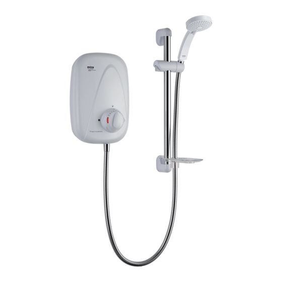
22. DO NOT perform any unspecified modifications, or drill or cut holes in the product other than instructed by this guide. When servicing only use genuine Kohler Mira replacement parts. 23. Always check the water temperature is safe before entering the shower. 24. The water supplies to this product must be isolated if the product is not to be used for a long period of time. - Page 5 INTRODUCTION The Mira GO Thermostatic Power Shower is an all-in-one power shower with an integral mains voltage pump and separate controls for flow and temperature. It features a 15 mm dual entry push-fit manifold which supports various inlet supply configurations. The manifold includes inlet filters and check valves. The thermostatic mixer incorporates a wax capsule sensing unit. Designed to be surface mounted the Thermostatic Power Shower comes complete with an adjustable spray handset with three settings, flexible hose, adjustable slider, sliding rail, soap tray and bracket.
-
Page 6: Pack Contents
PACK CONTENTS Tick the appropriate boxes to familiarise yourself with the part names and to confirm that the parts are included. 1 x Thermostatic Power Shower 4 x Case Inserts 1 x Flow Control Knob ... - Page 7 DIMENSIONS All dimensions are nominal and in millimetres. 1079321-W2-G...
-
Page 8: Specifications
Approvals Approvals The Mira GO Thermostatic Power Shower complies w i t h U K C A & C E The Mira Vigour Thermostatic Power Shower complies with UKCA & CE standards. s t a n d a r d s . -
Page 9: Installation Requirements
INSTALLATION REQUIREMENTS Gravity Fed system - The shower MUST be fed from a cold water cistern and hot water cylinder providing nominally equal pressure. 30° - 60° 10 m Maximum 80 mm Minimum 1.5 m Max. Head Hose Retaining Ring 1079321-W2-G... -
Page 10: Installation
INSTALLATION General Do not take risks with plumbing or electrical equipment. Do not install the shower unit in a position where it could become frozen. Isolate electrical and water supplies before proceeding with the installation of the shower unit. The shower unit must be fed from a cold water storage cistern and hot water cylinder with equal pressures. - Page 11 Plumbing A minimum storage capacity of cold water of 230 litres (50 gallons) is required to provide adequate showering time. Insufficient storage may result in the pump being run dry. Layout and sizing of pipework must be such that nominally equal inlet supply pressures are achieved and the effects on the shower performance of other draw-offs are minimised. Make sure the shower unit is the first draw-off from the water supply. Avoid routing the high level hot feed pipe upward to the same level as the cold tank e.g.
- Page 12 Warning! Do not fix the shower unit to the wall until plumbing and electrical installations have been completed. Decide on a suitable location for the shower unit avoiding buried cables and pipes. The unit should be positioned at a height convenient for all the family (at least 200 mm below the ceiling to allow for the fitting and removal of the unit cover).
- Page 13 Make sure that the end of the supply Chamfer pipework is cut squarely and is free from burrs, which will damage the inlet manifold seals. Chamfer the end of the pipe to assist insertion into the fitting and prevent the ‘O’ seal tearing. Warning! Do not insert fingers into the push-fit connectors as this can...
- Page 14 Temporarily locate the shower unit. Position the shower unit on the wall and mark the three fixing points. Note! Installers may wish to obtain alternative proprietary cavity fixings for dry lined, stud partition or dry partition wall structures. 9. Use the push-fit release tool to push the grey collars into the manifold to release the shower unit from the supply pipes.
- Page 15 12. Fit the three rubber feet into the Rubber Feet recesses in the rear of the case as shown. The feet will reduce the noise transmitted by the power shower through the wall. Warning! Blanking plates should be fitted to stop water ingress into the inside of the unit. 13.
- Page 16 14. Locate the shower unit on the inlet supplies and push the inlet manifold onto the pipework until resistance is felt. DO NOT FORCE! Note! PTFE tape or liquid jointing compound must not be used and is not required to assist connection. 15.
- Page 17 Refit the unit cover and secure with the three cover securing screws. OFF Position Insert the flow control knob in the OFF position. 21. Insert the temperature indicator trim and the inner temperature control knob. 22. The power thermostatic shower will Temperature now require commissioning, refer to Control Knob...
- Page 18 COMMISSIONING The unit must not be run dry. Before proceeding any further with the installation the shower unit must be commissioned. Connect the flexible hose to the outlet of the shower unit. Hose Washer Caution! Do not over tighten. Hose Turn on the water supplies and check for leaks.
- Page 19 Maximum Temperature Setting It may be necessary to adjust the maximum temperature for site conditions to make sure of safe showering from the unit. Make sure that the hot water temperature is at least 12 °C above the required temperature for correct operation of the thermostatic power shower.
- Page 20 Caution! When resistance is felt DO NOT USE FORCE to turn the spindle any further as this is the maximum shower temperature obtainable with the available hot water storage temperature. FORCE will DAMAGE the internal components. Turn the temperature spindle until the maximum water temperature required Temperature Spindle is obtained.
- Page 21 Disabling the Temperature Override Button The temperature override button allows the user to override the preset maximum temperature. The temperature override button should be disabled if the power shower is to be used by the young, the elderly, the infirm, or anyone inexperienced in the correct operation of the controls.
-
Page 22: Operation
OPERATION For safety reasons this appliance is fitted with an adjustable maximum temperature setting. This must be checked and adjusted as necessary to suit both site conditions and user’s comfort. Turn the outer flow control knob until the desired flow of water is obtained. -
Page 23: Fault Diagnosis
FAULT DIAGNOSIS Fault Diagnosis - User Maintenance The appliance is fully performance tested after assembly. Providing it has been correctly installed and is operated as advised, difficulties should not arise. In the unlikely event that you experience problems with your appliance then the following procedure will enable you to undertake basic fault finding before contacting the person responsible for installing your shower. - Page 24 In the event of any of the following tests failing, re-check as appropriate before contacting the Mira Showers Customer Support Department, refer to the rear page. Malfunction...
- Page 25 Malfunction Cause Remedy The maximum Hot water cylinder Adjust the cylinder shower temperature less than temperature. Note! It is temperature is too 12 °C above the showering recommended that the stored cold. temperature. water temperature does not exceed 65 °C. Maximum temperature Reset the maximum incorrectly set.
-
Page 26: Maintenance
MAINTENANCE Warning! There are no user serviceable components beneath the cover of the appliance. Only a competent tradesperson should remove the cover. Before removing the cover the electricity supply must be turned off at the mains and, if applicable, the appropriate circuit fuse removed. Mains electrical connections are exposed when the cover is removed. -
Page 27: Spare Parts
SPARE PARTS 147.67 Check Valve Pack 453.01 Cartridge - Thermostatic 453.03 Motor Pump Assembly - components identified ‘A’ 453.07 Inlet Manifold Assembly - components identified ‘B’ 453.08 PCB Assembly - Power 453.12 Harness Assembly - Concentric - components identified ‘C’ 453.13 Solenoid Valve Assembly - components identified ‘D’... - Page 28 A,D,E 453.08 453.28 1532.335 147.67 B,E,F 453.01 453.14 1532.332 1079321-W2-G...
- Page 29 ACCESSORIES Genuine Mira accessories can be purchased direct from Customers Services (our contact details can be found on the back cover of this guide) or from approved stockists or merchants. Shower Seat Premium Shower Seat White - 2.1536.128 White/Chrome - 2.1731.001 White/Chrome - 2.1536.129...
- Page 30 NOTES 1079321-W2-G...
- Page 31 NOTES 1079321-W2-G...
-
Page 32: Customer Service
Eire ● Products purchased ex-showroom display. T: 01 531 9337 ● Disinfection or descaling to reduce bacterial E: customerserviceeire@mirashowers.com growth or contamination. www.mirashowers.ie Mira is a registered trade mark Registered Offi ce: EU Importer address of Kohler Mira Limited. Cromwell Road, K/E S.A.S. Cheltenham,...