MULTIQUIP Whiteman Series Operation And Parts Manual
Power buggy
Hide thumbs
Also See for Whiteman Series:
- Manual (100 pages) ,
- Operation and parts manual (82 pages) ,
- Operation manual (80 pages)
Table of Contents
Advertisement
Quick Links
Advertisement
Table of Contents

Related Manuals for MULTIQUIP Whiteman Series


Summary of Contents for MULTIQUIP Whiteman Series
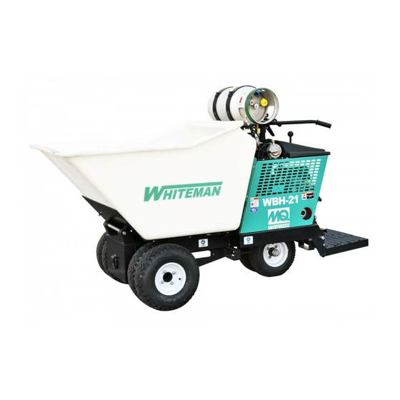
- Page 1 OPERATION AND PARTS MANUAL SERIES MODEL WBH-21EFP POWER BUGGY (B&S VANGUARD 18 HP PROPANE DRIVEN ELECTRIC START) Revision #0 (03/06/18) To find the latest revision of this publication, visit our website at: www.multiquip.com THIS MANUAL MUST ACCOMPANY THE EQUIPMENT AT ALL TIMES.
-
Page 2: Proposition 65 Warning
PROPOSITION 65 WARNING Engine exhaust some its constituents, and some dust created by power sanding, sawing, grinding, drillingandotherconstructionactivities contains chemicals known to the State of California to cause cancer, birth defects and other reproductive harm. Some examples of these chemicals are: Leadfromlead-basedpaints. -
Page 3: Table Of Contents
TABLE OF CONTENTS WBH-21EFP POWER BUGGY Component Drawings Proposition 65 Warning ........... 2 Nameplate And Decals Assembly..... 44-45 Table Of Contents ............ 3 Hydraulic Drive Assembly ......... 46-47 Parts Ordering Procedures ........4 Hydraulic Pump Assembly ........ 48-49 Safety Information ..........5-11 Hydraulic Dump Assembly ....... -
Page 4: Parts Ordering Procedures
, 2006 Order via Internet (Dealers Only) Best Deal! If you have an MQ Account, to obtain a Username Order parts on-line using Multiquip’s SmartEquip website! and Password, E-mail us at: parts@multiquip. com. ■ View Parts Diagrams ■ Order Parts To obtain an MQ Account, contact your District Sales Manager for more information. -
Page 5: Safety Information
SAFETY INFORMATION Do not operate or service the equipment before reading Potential hazards associated with the operation of this the entire manual. Safety precautions should be followed equipment will be referenced with hazard symbols which at all times when operating this equipment. may appear throughout this manual in conjunction with Failure to read and understand the safety safety messages. - Page 6 „ NEVER use accessories or attachments that are not „ Avoid wearing jewelry or loose fi tting clothes that may recommended by Multiquip for this equipment. Damage snag on the controls or moving parts, as this can cause to the equipment and/or injury to the user may result.
- Page 7 SAFETY INFORMATION POWER BUGGY SAFETY CAUTION „ ALWAYS inspect the surface over which you will travel. DANGER Look for holes, drop-offs, and obstacles. Look for rough „ Engine fuel exhaust gases contain poisonous carbon and weak spots on docks, ramps or fl oor. Look for oil monoxide.
- Page 8 SAFETY INFORMATION „ DO NOT operate the power buggy at excessive speeds. „ ALWAYS block the power buggy with appropriate blocks Reckless operation may cause accidents and severe when leaving the power buggy parked on a slope. injury. Slow down when approaching people, wet areas, „...
- Page 9 SAFETY INFORMATION FUEL SAFETY (LPG/PROPANE) ENGINE SAFETY DANGER WARNING „ ALWAYS use extreme caution when handling propane. „ DO NOT place hands or fi ngers inside the Propane is fl ammable and explosive and can cause engine compartment when the engine is serious personal injury or death if not handled running.
- Page 10 SAFETY INFORMATION „ DO NOT charge the battery if frozen. The battery can CAUTION explode. When frozen, warm the battery to at least „ NEVER use propane tanks that are fi lled beyond 80% 61°F (16°C). capacity. „ ALWAYS recharge the battery in a well-ventilated „...
- Page 11 SAFETY INFORMATION TRANSPORTING SAFETY „ When the life cycle of this equipment is over, it is recommended that the unit frame and all other metal NOTICE parts be sent to a recycling center. Metal recycling involves the collection of metal from „...
-
Page 12: Specifications (Buggy)
SPECIFICATIONS (BUGGY) Table 1. Specifications (Power Buggy) Model WBH-21EFP Maximum Weight Capacity 3,200 lbs. (1,451 kg) (Dual Wheels) Operating Weight 1,492 lbs. (677 kg.) Bucket/Tub Capacity 21 cu. ft. Water Level (.78 cu. yd.) Bucket/Tub Material Polyethylene Drive Hydrostatic Speed Up to 7.25 mph. -
Page 13: Specifications (Engine)
SPECIFICATIONS (ENGINE) Table 2. Specifications (Engine) Model Briggs and Stratton Vanguard Type Twin Cylinder, Overhead Valve, Air Cooled Bore X Stroke 2.82 x 2.75 in. (71.88 x 69.85 mm) Displacement 34.7 cu. in. (570 cc) Maximum Power 18.0 hp (3,600 rpm) 31.70 ft-lbs. -
Page 14: Dimensions
DIMENSIONS SIDE VIEW WBH-21EFP FRONT VIEW Table 3. Dimensions Reference Dimension Letter in. (mm) 45.47 (1,155) 51.0 (1,295) 8.50 (216) 103 (2,612) 44 (1,117) Figure 1. WBH21-EFP Dimensions PAGE 14 — WBH-21EFP POWER BUGGY • OPERATION AND PARTS MANUAL — REV. #0 (03/01/18) -
Page 15: General Information
GENERAL INFORMATION The MQ Whiteman Power Buggy, Model WBH-21EFP The engine drives a variable displacement hydrostatic (recoil/electric start) is intended for the transportation of transmission which is activated by a cable controlled concrete, concrete spreading and spot pouring. In addition, hand lever. -
Page 16: Components
COMPONENTS 9. Parking Brake Lever — When this lever is activated (pulled up), the parking brake will be set. To release the brake, pull the lever downwards. 10. Hydraulic Tank/Cap — Remove this cap to add hydraulic oil. Tank holds approximately 5.3 U.S. gallons (20.4 liters). -
Page 17: Basic Engine
BASIC ENGINE Figure 3. Briggs & Stratton Vanguard 18HP Engine 1. Air Filter — Prevents dirt and other debris from 7. Oil Drain Plug — Remove to drain crankcase oil. entering the fuel system. Release the latches on 8. Engine — This machine uses an electric start Briggs the sides of the air filter cover to gain access to filter &... -
Page 18: Inspection
INSPECTION BEFORE STARTING 6. When checking the engine oil, be sure to check if the oil is clean. If the oil is not clean, drain the oil by removing 1. Read safety information at the beginning of manual. the oil drain plug, and refill with the specified amount of oil as outlined in the maintanence section of this 2. - Page 19 INSPECTION Procedure For Removing Propane Vapor Tank BATTERY This unit is of negative ground DO NOT connect in reverse. 1. Place machine on secure level ground where it will not slip or slide. ALWAYS maintain battery fluid level between the specified marks.
- Page 20 INSPECTION PARKING BRAKE CHECK When connecting battery do the following: 1. NEVER connect the battery cables to the battery Check the brakes as outlined in the maintenance section terminals when the ignition is in the ON position (start). of this manual. 2.
-
Page 21: Operation
OPERATION ELECTRIC START (METHOD) 4. Move the throttle lever halfway between the FAST and SLOW position (Figure 15) for starting. 1. Before attempting to start the power buggy, make sure that the safety kill switch (Figure 12) is not pushed in. - Page 22 OPERATION PRE-CHECK 6. Place the ignition key (Figure 17 ) in the START position and hold it until the engine starts. When the engine 1. Engage the parking brake lever (Figure 19) and attempt starts, release the key, allowing it to return back to the to rock the buggy back and forth.
- Page 23 OPERATION PARKING BRAKE/DIRECTION LEVER TRAVELING Before the power buggy can be put into operational use, 1. With the engine running and parking brake released, it is best to perform a test run to make certain that all place the direction lever (Figure 21) in the forward components are functioning properly.
- Page 24 OPERATION STEERING To steer the buggy, use the handle bar in front of the operator platform. 1. To turn left when traveling in the forward direction, turn the handle bar clockwise (Figure 23). DISTANCE (D) HEIGHT (H) TURN HANDLE BAR % GRADE = 100 (H¸...
- Page 25 OPERATION TUB (BUCKET) DUMPING The hydraulic dump can be controlled by the hand dump control lever or foot dump pedal. NOTICE 1. To place the tub in the vertical position press down on DO NOT activate dump mechanism (tub/bucket) if the dump pedal (Figure 26A) or move the dump control buggy is facing down hill.
- Page 26 OPERATION SHUTDOWN (NORMAL) 5. Cycle hydraulic controls to eleminate residual pressure. 6. CLOSE the fuel shutoff valve (Figure 30). on the Correct shutdown is important to safe operation. Follow propane tank. these general steps: 1. Come to a full stop. 2.
-
Page 27: Maintenance
MAINTENANCE Table 5. Engine Maintenance Schedule EVERY 6 EVERY BEFORE FIRST EVERY 2 DESCRIPTION EVERY MONTHS YEAR OPERATION EACH MONTH OR YEARS OR 40 Hours OR 100 OR 300 25 HRS. 500 HRS. HRS. HRS. Check Engine Oil Change Engine Oil Filter Replace Every 100 Hrs. - Page 28 MAINTENANCE AIR CLEANER (100 HOURS) When performing any maintenance on the power buggy or engine, follow all safety messages and rules for safe Thoroughly remove dirt and oil from the engine and operation stated at the beginning of this manual. control area.
- Page 29 MAINTENANCE CHANGING ENGINE OIL (100 HOURS) 6. To clean the paper air filter (Figure 33), tap the filter element several times on a hard surface to remove 1. Drain the engine oil when the oil is warm as shown in dirt, or blow compressed air [not to exceed 30 psi (207 (Figure 35).
- Page 30 MAINTENANCE PROPANE TANK AND COMPONENTS PROPANE TANK LEAK DETECTION Inspection (Daily) 1. Apply an approved leak detector (Figure 38) solution, obtained from a trained and qualified propane distributer, CAUTION or a thick non-ammonia soapy water solution (1:1 mixture of 1 part non-ammonia soap and 1 part of water). NEVER use bare hands when checking for leaks.
- Page 31 MAINTENANCE TROUBLE SHOOTING PROPANE FUEL SYSTEMS SPARK PLUG ADJUSTMENT DANGER 1. Make sure the engine is cool before servicing the spark plugs. Use extreme caution when handling propane. Propane is flammable and explosive and can cause personal 2. Disconnect the spark plug caps. Check for dirt and injury if not handled properly.
- Page 32 MAINTENANCE ADDING HYDRAULIC OIL 5. Use the tub support rod to support the tub, then turn the engine OFF. 1. Check the hydraulic oil level in the hydraulic oil tank, 6. Remove the two bolts that secure the access by reading the hydraulic oil sight glass (Figure 40) cover(Figure 42) to the buggy frame.
- Page 33 OIL TANK Figure 46. Hydraulic Drive Motor Figure 44. Adding Hydraulic Oil NOTICE Contact Multiquip's Service Department should any NOTICE problems develop with the hydraulic drive motors In climates where temperatures are below 35°F (1.6°C), hard starting may occur. In these cases, the hydraulic oil BRAKE ADJUSTMENT should be switched to a thinner 15 weight hydraulic fluid.
- Page 34 MAINTENANCE PUMP CONTROL LEVER ADJUSTMENT 3. Adjust the knob sufficiently tight so that when the parking brake lever is pulled upward to the engaged Inspect the speed control return springs. The tension should position (set), there is a sufficient amount of tension. be sufficient to allow lever to snap back when released.
- Page 35 MAINTENANCE TIRES/WHEELS/LUG NUTS Table 7. Tire Torque Requirements First Pass Second Pass Third Pass Tires and wheels are very important and critical components Wheel Size FT-LBS FT-LBS FT-LBS of the buggy. When specifying or replacing the wheels, it is important that the wheels, tires, and axle are properly 480 x 8 in.
-
Page 36: Troubleshooting
TROUBLESHOOTING Troubleshooting (Power Buggy) Symptom Possible Problem Solution Adjust speed control cable. Replace cable if Speed control cable out of adjustment? necessary Hydraulic oil level low.? Check hydraulic oil level. Add oil if necessary. Loss of Power. Contaminated hydraulic oil fi lter? Replace hydraulic oil fi lter. - Page 37 TROUBLESHOOTING Troubleshooting (Engine) Symptom Possible Problem Solution Spark plug bridging? Check gap, insulation or replace spark plug. Carbon deposit on spark plug? Clean or replace spark plug. Short circuit due to defi cient spark plug Check spark plug insulation, replace if worn. insulation? Improper spark plug gap? Set to proper gap.
- Page 38 TROUBLESHOOTING Troubleshooting (Engine) - continued Symptom Possible Problem Solution Air cleaner dirty? Clean or replace air cleaner. Improper level in carburetor? Check fl oat adjustment, rebuild carburetor. Weak in power, compression is proper and does not misfi re. Defective spark plug? Clean or replace spark plug.
-
Page 39: Hydraulic System Diagram
HYDRAULIC SYSTEM DIAGRAM HYDRAULIC OIL TANK HYD. OIL FILTER 200 MICRON DUMP CYLINDER SCREEN/MESH CHARGE PUMP RELIEF VALVE 1000 PS1 ± 50 EATON PUMP 17 GPM SPIN-ON RETURN FILTER 10 MICRON DIRECTION VALVE DUMP VALVE DRIVE MOTOR DRIVE MOTOR NORMALLY UP TO NORMALLY UP TO 17 GPM 17 GPM... -
Page 40: Hydraulic Hose Connections
HYDRAULIC HOSE CONNECTIONS HYDRAULIC PUMP DUMP CYLINDER HYDRAULIC OIL TANK FRAME HYDRAULIC OIL FILTER DUMP VALVE DRIVE MOTORS PAGE 40 — WBH-21EFP POWER BUGGY • OPERATION AND PARTS MANUAL — REV. #0 (03/01/18) -
Page 41: Engine Wiring Diagram
ENGINE WIRING DIAGRAM IGNITION SWITCH POSITION CIRCUIT MAKE G+M+A B+L+A B+L+S START 12 AWG 12 AWG SPLICE 12 AWG SPARK IGNITION PLUG SWITCH 12 AWG (RIGHT) UNIT 12 AWG IGNITION CHASSIS GND. COIL 12 AWG SPARK 12 AWG IGNITION PLUG (RIGHT) SWITCH CONNECTOR... -
Page 42: Explanation Of Code In Remarks Column
A blank entry generally indicates that the item is not sold “Not Sold Separately” — Indicates that an item cannot separately or is not sold by Multiquip. Other entries will be purchased as a separate item and is either part of an be clarifi ed in the “Remarks”... -
Page 43: Suggested Spare Parts
SUGGESTED SPARE PARTS WBH-21EF POWER BUGGY B&S VANGUARD 18 HP GASOLINE ENGINE 1 to 3 units 1 to 3 units Qty. Description Qty. Description 1....508667 ....FILTER, HYDRAULIC OIL 3....496018S ....SPARK PLUG 1....EM16477 ....CAP, HYDRAULIC OIL TANK 3....691959 ....KEY, IGNITION 1....18035 ....PUMP, HYDROSTATIC 3....808167 ....GRIP, STARTER 1....18051 ....COUPLING, ENGINE SHAFT 1....66574 ....ROPE, STARTER... -
Page 44: Nameplate And Decals Assembly
NAMEPLATE AND DECALS ASSY. WARNING CRUSH AREA 18247 LIFT 513608 TRAVEL NEUTRAL SAFETY INSTRUCTIONS 1. Read owner’s manual before operating. MODEL SERIAIAL NO. 2. Keep unauthorized and untrained people away from machine during operation. 3. Make sure all safety devices are in place before this machine is started. - Page 45 NAMEPLATE AND DECALS ASSY. PART NO. PART NAME QTY. REMARKS 18247 DECAL, CRUSH WARNING DECAL, TRAVEL LEVER DIRECTION .....1..MOLDED INTO FUEL TANK COVER PLATE, SERIAL NUMBER........1..CONTACT MQ PARTS DEPT. 491757 RIVET, I.D. PLATE 18248 DECAL, HOT SURFACE WARNING 804592 DECAL, WBH-21 18252 DECAL, MQ WHITEMAN 18245...
-
Page 46: Hydraulic Drive Assembly
HYDRAULIC DRIVE ASSY. VIEW FROM OPERATOR’S PLATFORM DIRECTIONAL VALVE SEAL KIT DRIVE MOTOR LEFT DRIVE MOTOR RIGHT DRIVE MOTOR NOTES: REFERENCE HYDRAULIC HOSE CONNECTION SECTION. REFERENCE PUMP ASSEMBLY. PAGE 46 — WBH-21EFP POWER BUGGY • OPERATION AND PARTS MANUAL — REV. #0 (03/01/18) - Page 47 HYDRAULIC DRIVE ASSY. PART NO. PART NAME QTY. REMARKS 18265M HOSE, DIRECTION VALVE .........1....RIGHT-DRIVE MOTOR 18264M HOSE, DIRECTION VALVE .........1....LEFT-DRIVE MOTOR 511810 ADAPTER, ELBOW 18276M HOSE, LH HYDRAULIC MOTOR 512189 ADAPTER, TEE CONNECTOR 492527 NUT, HEX 1/2"-20 18029F WHEEL, DRIVE ASSY. FRONT ......4....FOAM FILLED TIRE 511692 FLANGE, HUB 18237...
-
Page 48: Hydraulic Pump Assembly
HYDRAULIC PUMP ASSY. HYDRAULIC PUMP DIRECTION VALVE SEAL KIT DIRECTIONAL VALVE HYDRAULIC OIL FILTER DUMP VALVE NOTES: REFERENCE HYDRAULIC HOSE CONNECTION SECTION. REFERENCE HYDRAULIC OIL TANK ASSEMBLY. REFERENCE DUMP VALVE ASSEMBLY. REFERENCE HYDRAULIC DRIVE ASSEMBLY ITEMS 1 AND 2 FOR HOSE PART NUMBERS PAGE 48 —... - Page 49 HYDRAULIC PUMP ASSY. PART NO. PART NAME QTY. REMARKS 18035 PUMP, HYDRAULIC 511808 ADAPTER, STRAIGHT 3365 ADAPTER, STRAIGHT 18256M HOSE, PUMP TO DUMP VALVE 18258M HOSE, FILTER TO PUMP 18261M HOSE, PUMP TO TANK 18265M HOSE, PUMP TO DIRECTION VALVE ....1....REPLACES P/N 18263M 512190 ADAPTER, STRAIGHT 18257M...
-
Page 50: Hydraulic Dump Assembly
HYDRAULIC DUMP ASSY. DUMP CYLINDER SEAL KIT DUMP CYLINDER DUMP VALVE NOTES: REFERENCE HYDRAULIC HOSE CONNECTION SECTION. REFERENCE HYDRAULIC PUMP ASSEMBLY ITEM 4 FOR HOSE PART NUMBER. REFERENCE HYDRAULIC PUMP ASSEMBLY ITEM 9 FOR HOSE PART NUMBER. REFERENCE HANDLE/FOOT DUMP CONTROLS ASSEMBLY ITEM 8 FOR DUMP VALVE PART NUMBER. - Page 51 HYDRAULIC DUMP ASSY. PART NO. PART NAME QTY. REMARKS 803747 CYLINDER, HYDRAULIC DUMP 18022SK SEAL KIT, DUMP CYLINDER EM916019 ZERK FITTING ..........2....REPLACES P/N 491705 511803 ADAPTER, ELBOW 18020 HOSE, DUMP VALVE TO HYD. PISTON 511804 ADAPTER, ELBOW MALE 512234 ADAPTER, ELBOW 511806 ADAPTER, STRAIGHT 506191...
-
Page 52: Pump And Coupling Assembly
PUMP AND COUPLING ASSY. Engine HYDRAULIC PUMP NOTES: ITEMS 2A THROUGH 2D NOT INCLUDED WITH ITEM 2. FRAME 2 APPLY BLUE LOCTITE PAGE 52 — WBH-21EFP POWER BUGGY • OPERATION AND PARTS MANUAL — REV. #0 (03/01/18) - Page 53 PUMP AND COUPLING ASSY. PART NO. PART NAME QTY. REMARKS 492472 SCREW, ALLEN HEAD 3/8"-16 X 3/4" 18051 COUPLING, ENGINE SHAFT .........1 ....INCLUDES ITEMS W/# 18051RS SPIDER, URETHANE 492356 SCREW, 1/4" X 3/4" GRD 5 2101402 WASHER, LOCK 1/4" ..........1 ....REPLACES P/N 492622 EM923057 WASHER, FLAT 3/4"...
-
Page 54: Tub Assembly
TUB ASSY. PAGE 54 — WBH-21EFP POWER BUGGY • OPERATION AND PARTS MANUAL — REV. #0 (03/01/18) - Page 55 TUB ASSY. PART NO. PART NAME QTY. REMARKS 804580 TUB, PLASTIC 21 CU. FT. EM963057 SCREW, HHC 3/8"-16 X 1-1/2" ......9....REPLACES P/N 492313 512193 WASHER, FLAT 3/8" 490957 RING, SNAP 18130 PIN, HYD. PISTON CROSS 18129 PIN, TUB FRAME CROSS 0202 SCREW, HHC 5/16"-18 X 1 ZINC ......4....REPLACES P/N 492364 EM923023...
-
Page 56: Panel Assembly
PANEL ASSY. PAGE 56 — WBH-21EFP POWER BUGGY • OPERATION AND PARTS MANUAL — REV. #0 (03/01/18) - Page 57 PANEL ASSY. PART NO. PART NAME QTY. REMARKS 503978 POP RIVET AM-56 511474 FASTENER, ACCESS DOOR 18008 DOOR, ACCESS 1579 SCREW, 1/4" NC X 1/2" GRD 5 ......2....REPLACES P/N 492355 EM923023 WASHER, FLAT 3/8" .........32....REPLACES P/N 492597 18141 COVER, RIGHT/SIDE ENGINE 0202 SCREW, HHC 5/16"-18 X 1"...
-
Page 58: Brake Assembly
BRAKE ASSY. PAGE 58 — WBH-21EFP POWER BUGGY • OPERATION AND PARTS MANUAL — REV. #0 (03/01/18) - Page 59 BRAKE ASSY. PART NO. PART NAME QTY. REMARKS 511762 SCREW, HHC 1/2"-13 X 8" 511698 CLEVIS, ASSY. BRAKE EM492574 NUT, HEX 3/8"-24 ..........2....REPLACES P/N 492574 18111 PEDAL, BRAKE EM621 WASHER, FLAT 1/2" ..........1....REPLACES P/N 621 492584 NUT, NYLOC 1/2"-13 18167 SPRING, BRAKE PEDAL 18307 SPRING, BRAKE...
-
Page 60: Steering And Controls Assembly
STEERING AND CONTROLS ASSY. HYDRAULIC OIL TANK HYDROSTATIC PART OF MOTOR BASE NOTES: BEARING, ITEM 27 AND BUSHING ITEM 31 ARE LOCATED INSIDE STEERING AXLE. PAGE 60 — WBH-21EFP POWER BUGGY • OPERATION AND PARTS MANUAL — REV. #0 (03/01/18) - Page 61 STEERING AND CONTROLS ASSY. PART NO. PART NAME QTY. REMARKS 2508 SCREW, HHC 1/4"-20 X 2-1/4" ......1....REPLACES P/N 512414 492369 SCREW, HHC 5/16"-18 X 2-1/4" 18183 ROD-END, THROTTLE CABLE 2105164 NUT, NYLOC 5/16"-18 ........1....REPLACES P/N 492582 EM504505 WRAP, TIE 4.6 X 360 MM ........1....REPLACES PN 504505 491030 WRAP, TIE 2.5 X 142 MM 505304...
-
Page 62: Chassis Assembly
CHASSIS ASSY. PAGE 62 — WBH-21EFP POWER BUGGY • OPERATION AND PARTS MANUAL — REV. #0 (03/01/18) - Page 63 CHASSIS ASSY. PART NO. PART NAME QTY. REMARKS EM969013 NUT, NYLOC 3/8" ..........10....REPLACES P/N 492583 3019092 WASHER, FLAT 3/8" .........18....REPLACES P/N 492598 EM963057 SCREW, HHC 3/8"-16 X 1-1/2" ......3....REPLACES P/N 492313 503112 SCREW, HHC 3/8"-16 X 2-3/4" EM963610 SCREW, HHC 3/8" X 1-1/4" GRD 8 ....2....REPLACES P/N 492375 492356 SCREW, HHC 1/4"...
-
Page 64: Handle/Foot Dump Controls Assembly
HANDLE/FOOT DUMP CONTROLS ASSY. SEAL KIT DUMP VALVE REFERENCE HYDRAULIC DUMP ASSY. PAGE 64 — WBH-21EFP POWER BUGGY • OPERATION AND PARTS MANUAL — REV. #0 (03/01/18) - Page 65 HANDLE/FOOT DUMP CONTROLS ASSY. PART NO. PART NAME QTY. REMARKS 492401 SCREW, HHC 1/2"-13 X 4 503119 NUT, NYLOC 3/16" 18121 KNOB, LEVER 18065 LEVER, DUMP VALVE 512185 SCREW, HHC 1/4"-20 X 1-3/4" 492622 WASHER, FLAT 1/4" 512183 SCREW, HHC 3/16"-24 X 1-1/4" 18064 VALVE, DUMP ...........1....INCLUDES ITEMS W/$ 18064SK...
- Page 66 HYDRAULIC OIL TANK ASSY. PAGE 66 — WBH-21EFP POWER BUGGY • OPERATION AND PARTS MANUAL — REV. #0 (03/01/18)
- Page 67 HYDRAULIC OIL TANK ASSY. PART NO. PART NAME QTY. REMARKS 520461 RETAINER 801791 O-RING 520460 COVER 520343 O-RING 510717 BOLT, 1/2"NC X 1-3/4" EM16477 CAP, HYDRAULIC OIL TANK 18125 TANK, HYDRAULIC OIL EM963610 SCREW, HHC 3/8" X 1-1/4" .......3....REPLACES P/N 492376 3019092 WASHER, FLAT 3/8"...
-
Page 68: Battery Assembly
BATTERY ASSY. PAGE 68 — WBH-21EFP POWER BUGGY • OPERATION AND PARTS MANUAL — REV. #0 (03/01/18) - Page 69 BATTERY ASSY. PART NO. PART NAME QTY. REMARKS 505500 WINGNUT 512557 BATTERY CABLE, NEGATIVE 511250 BATTERY CABLE, POSITIVE 512555 BATTERY SUPPORT BRACKET EM92305 WASHER, FLAT 1/4" ..........6....REPLACES P/N 492596 2101402 WASHER, LOCK 1/4" ........2....REPLACES P/N 492622 508480 BATTERY SUPPORT PLATFORM 503118 BOLT 3/16"...
-
Page 70: Carburetor Assembly
CARBURETOR ASSY. PAGE 70 — WBH-21EFP POWER BUGGY • OPERATION AND PARTS MANUAL — REV. #0 (03/01/18) - Page 71 CARBURETOR ASSY. PART NO. PART NAME QTY. REMARKS PS692081 AIR CLEANER GASKET PS327431 SCREW, BTN. HD. SOC 1/4"-20X5/8" PS32533 WASHER, LOCK 1/4" PS453023 WASHER, FLAT 1/4" PS809062 SHAFT, THROTTLE PS690722 SPACER, NEOPRENE PS806132 VALVE, THROTTLE PS690718 SCREW, THROTTLE SHAFT PS699721 KIT, IDLE SPEED PS260418 SET SCREW 10-32X1/4"...
-
Page 72: Regulator And Vacuum Assembly
REGULATOR AND VACUUM VALVE ASSY. PAGE 72 — WBH-21EFP POWER BUGGY • OPERATION AND PARTS MANUAL — REV. #0 (03/01/18) - Page 73 REGULATOR AND VACUUM VALVE ASSY. PART NO. PART NAME QTY. REMARKS R151471 PRESSURE REGULATOR R151216 BRASS 90° MALE ELBOW 3/8"X1/4" NPT R151238 CLAMP, SCREW #10 PS150013 LOW PRESSURE HOSE, 50" PSVB1 SCHRADER VALVE R151298 BRASS 90° ELBOW 3/8"X1/2" NPT BARB PS150012 HIGH PRESSURE HOSE 14"...
-
Page 74: Propane Tank Assembly
PROPANE TANK ASSY. PAGE 74 — WBH-21EFP POWER BUGGY • OPERATION AND PARTS MANUAL — REV. #0 (03/01/18) - Page 75 PROPANE TANK ASSY. PART NO. PART NAME QTY. REMARKS R151166 STRAP, PROPANE TANK R151330 TANK, 33.5 LB. PROPANE, HORIZONTAL VAPOR R3224 BOLT, HEX HD. 5/16-18"X7/8" R453009 WASHER, FLAT 5/16" SAE PS150010 TANK STAND ASSY. PS150011 CHASSIS PLATE ASSY. R300102 BOLT, HEX HD. 5/16-18"X1" GR5 R1048300 LOCKNUT, 5/16-18"...
-
Page 76: Engine Mounting Assembly
ENGINE MOUNTING ASSY. PAGE 76 — WBH-21EFP POWER BUGGY • OPERATION AND PARTS MANUAL — REV. #0 (03/01/18) - Page 77 ENGINE MOUNTING ASSY. PART NO. PART NAME QTY. REMARKS 3564470394G1 ENGINE, B&S 18HP VANGUARD 492581 NUT, NYLOC 5/6" EM923023 WASHER, FLAT 3/8" ..........4....REPLACES P/N 505679 513593 90° FITTING 513594 ADAPTER PLUG 492368 SCREW, 5/16" NC X 2" GRD 5 ......1....GROUND CONNECTION 2105162 SCREW, 5/16"...
-
Page 78: Engine Service Parts
ENGINE SERVICE PARTS PAGE 78 — WBH-21EFP POWER BUGGY • OPERATION AND PARTS MANUAL — REV. #0 (03/01/18) - Page 79 ENGINE SERVICE PARTS PART NO. PART NAME QTY. REMARKS 394018S AIR FILTER 272490S PRE-CLEANER 692318 IGNITION SWITCH, W/KEY 691959 IGNITION KEY SET 496018S SPARK PLUG, CHAMPION 66574 ROPE STARTER 808167 GRIP STARTER 842921 OIL FILTER WBH-21EFP POWER BUGGY • OPERATION AND PARTS MANUAL — REV. #0 (03/01/18) — PAGE 79...
-
Page 80: Terms And Conditions Of Sale - Parts
Multiquip be $5.00. meeting this requirement. liable for loss of profi t or good will or for any Special order items. - Page 81 NOTES WBH-21EFP POWER BUGGY • OPERATION AND PARTS MANUAL — REV. #0 (03/01/18) — PAGE 81...
- Page 82 © COPYRIGHT 2018, MULTIQUIP INC. Multiquip Inc , the MQ logo are registered trademarks of Multiquip Inc. and may not be used, reproduced, or altered without written permission. All other trademarks are the property of their respective owners and used with permission.