
Related Manuals for MULTIQUIP Whiteman HHN31VTCSL5


Summary of Contents for MULTIQUIP Whiteman HHN31VTCSL5
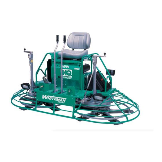
- Page 1 OperatiOn and parts Manual series MOdel hhn31vtCsl5 ride-On pOwer trOwel (B & s vanGuard dM950 GasOline enGine) Revision #8 (05/03/12) THIS MANUAL MUST ACCOMPANY THE EQUIPMENT AT ALL TIMES. pn: 20382...
- Page 2 We sell worldwide for the brands: Genie, Terex, JLG, MultiQuip, Mikasa, Essick, Whiteman, Mayco, Toro Stone, Diamond Products, Generac Magnum, Airman, Haulotte, Barreto,...
-
Page 3: Proposition 65 Warning
prOpOsitiOn 65 warninG Engine exhaust some its constituents, and some dust created by power sanding, sawing, grinding, drillingandotherconstructionactivities contains chemicals known to the State of California to cause cancer, birth defects and other reproductive harm. Some examples of these chemicals are: Leadfromlead-basedpaints. -
Page 4: Silicosis/Respiratory Warnings
siliCOsis/respiratOry warninGs WARNING WARNING SILICOSIS WARNING RESPIRATORY HAZARDS Grinding/cutting/drilling of masonry, concrete, metal and Grinding/cutting/drilling of masonry, concrete, metal and other materials with silica in their composition may give other materials can generate dust, mists and fumes off dust or mists containing crystalline silica. Silica is a containing chemicals known to cause serious or fatal basic component of sand, quartz, brick clay, granite and injury or illness, such as respiratory disease, cancer,... -
Page 5: Table Of Contents
taBle Of COntents hhn31vtCsl5 ride-On Component drawings power trowel Nameplates And Decals ........50-51 Pivot/Gearbox (Right Side) Assembly....52-53 Proposition 65 Warning ........... 2 Pivot/Gearbox (Left Side) Assembly....54-55 Silicosis/Respiratory Warnings ........ 3 Gearbox Assembly..........56-59 Table Of Contents ............ 4 Control Steering (Assist) 1 Assembly. -
Page 6: Training Checklist
traininG CheCklist Training Checklist Description Date Read operation manual completely. Machine layout, location of components, checking of engine oil levels. Fuel system, refueling procedure. Operation of spray and lights. Operation of controls (machine not running). Safety controls, safety stop switch operation. -
Page 7: Daily Pre-Operation Checklist
daily pre-OperatiOn CheCklist Daily pre-Operation Checklist Engine oil level Condition of blades Blade pitch operation Safety stop switch operation Steering control operation HHN31VTCSL5 RIDe-ON TROWeL • OpeRaTION aND paRTS maNuaL — ReV. #8 (05/03/12) — page 7... -
Page 8: Safety Information
safety infOrMatiOn Do not operate or service the equipment before reading Potential hazards associated with the operation of this the entire manual. Safety precautions should be followed equipment will be referenced with hazard symbols which at all times when operating this equipment. may appear throughout this manual in conjunction with Failure to read and understand the safety safety messages. - Page 9 „ NeVeR use accessories or attachments that are not „ Avoid wearing jewelry or loose fi tting clothes that may recommended by Multiquip for this equipment. Damage snag on the controls or moving parts as this can cause to the equipment and/or injury to user may result.
- Page 10 safety infOrMatiOn TROWeL SaFeTy NOTICE „ aLWayS keep the machine in proper running condition. DaNgeR „ Fix damage to machine and replace any broken parts „ Engine fuel exhaust gases contain poisonous carbon immediately. monoxide. This gas is colorless and odorless, and can cause death if inhaled.
- Page 11 safety infOrMatiOn BaTTeRy SaFeTy NOTICE „ NeVeR run engine without an air fi lter or with a dirty air DaNgeR fi lter. Severe engine damage may occur. Service air fi lter „ DO NOT drop the battery. There is a possibility that the frequently to prevent engine malfunction.
- Page 12 safety infOrMatiOn TRaNSpORTINg SaFeTy TOWINg SaFeTy CauTION CauTION „ NeVeR allow any person or animal to „ Check with your local county or state safety stand underneath the equipment while towing regulations, in addition to meeting Department of Transportation (DOT) lifting.
- Page 13 safety infOrMatiOn „ Trailer should be adjusted to a level position at all times when towing. „ Raise and lock trailer wheel stand in up position when towing. „ Place chock blocks underneath wheel to prevent rolling while parked. „ Place support blocks underneath the trailer’s bumper to prevent tipping while parked.
-
Page 14: Specifications/Dimensions
speCifiCatiOns/diMensiOns C HEIGHT B WIDTH A LENGTH Figure 1. HHN31VTCSL5 Dimensions Table 1. HHN31VTCSL5 Dimensions/Specifications Specification parameter HNN31V (Vanguard) A–Length – in. (cm) 97.0 (246.4) B–Width – in. (cm) 50.0 (127) C–Height – in. (cm) 46.0 (117) Weight – lbs. (kgs.) Operating 1,042 (477) Weight –... - Page 15 speCifiCatiOns Table 2. Noise and Vibration emissions Guaranteed ISO 11201:2010 Based Sound Pressure Level at Operator Station in dB(A) Guaranteed ISO 3744:2010 Based Sound Power Level in dB(A) Whole Body Vibration Per ISO 2631-1:1997+A1:2010 0.19 ∑A(8) in m/s NOTeS: Sound Pressure and Power Levels are “A” weighted Measures per ISO 226:2003 (ANSI S1.4-1981). They are measured with the operating condition of the machine which generates the most repeatable but highest values of the sound levels.
-
Page 16: General Information
Whiteman. Please training to a new operator. contact your nearest Multiquip Dealer for a replacement should the original manual disappear. BLaDeS The blades of the ride-on power trowel finish the concrete as they are swirled around the surface. - Page 17 nOtes HHN31VTCSL5 RIDe-ON TROWeL • OpeRaTION aND paRTS maNuaL — ReV. #8 (05/03/12) — page 17...
-
Page 18: Components
COMpOnents 1. Seat — Place for operator to sit. Engine will not start 10. Water Indicator Light — Lights red when water unless operator is seated. Seat is adjustable, fore and temperature is high. aft for operator comfort. 11. Charge Indicator — Lights red when electrical system 2. - Page 19 COMpOnents 20. eZ- mover Boss — Front -side insertion point for EZ 28. Overflow Bottle — Supplies coolant to the radiator Mover. Used when the transporting of the trowel is when radiator coolant level is low. Fill to indicated level required.
-
Page 20: New Machine Setup
new MaChine setup SeaT aSSemBLy The purpose of this section is to assist the user in setting up a NeW trowel. If the trowel is already assembled, (seats, The seat is not installed on the trowel for shipping purposes. handles, knobs and battery), this section can be skipped. To attach the seat, perform the following: NOTICE NOTICE... -
Page 21: Basic Engine
BasiC enGine Figure 5. Engine Components INITIaL SeRVICINg 8. Coolant Temperature Sending unit — Device that measures coolant temperature. The engine (Figure 5) must be checked for proper 9. governor Lever — This lever restricts engine speed lubrication and filled with fuel prior to operation. Refer to the (high idle or low idle) through a speed control device manufacturer’s engine manual for instructions and details linked to the accelerator system. -
Page 22: Inspection
inspeCtiOn This section is intended to assist the operator with the initial FILL PLUG inspection of the HHN trowel. It is extremely important that this section be read carefully before attempting to use the trowel in the field. GEAR BOX DO NOT use your trowel until this section is thoroughly DRAIN PLUG understood. -
Page 23: Operation
OperatiOn STaRTINg THe eNgINe 5. Turn the ignition key clockwise to the (start) position. The oil, charge, and preheat indicator lights (Figure 1. Place one foot on the trowel’s platform, grab ahold of 10) should be ON. any part of the frame, lift yourself onto the trowel, then NOTICE sit down in the operator’s seat. - Page 24 OperatiOn STeeRINg 4. Practice maneuvering the ride-on trowel using the information listed in Table 4. Try to practice controlled Two control levers located in front of the operator’s seat motions as if you were finishing a slab of concrete. provide directional control for the HHN trowel. Table 4 Practice edging and covering a large area.
-
Page 25: Maintenance
MaintenanCe When performing maintenance on the trowel or engine, 3. Replace gearbox lubricant. follow all safety messages and rules for safe operation 4. Check and adjust blade speed. stated at the beginning of this manual. WaRNINg See the engine manual supplied with your machine for Cer tain maintenance operations or machine appropriate engine maintenance schedule and adjustments require specialized knowledge and skill. - Page 26 MaintenanCe eNgINe OIL aND FILTeR PRIMING PUMP 1. Change the engine oil and filter after the first 5 hours of use, then change oil every 6 months or 150 hours. O-RING 2. Remove the oil filler cap (Figure 5), and fill engine crankcase with recommended type oil as listed in Table 5.
- Page 27 MaintenanCe BaTTeRy/CHaRgINg SySTem DaNgeR Flammable, explosive gas. (produces hydrogen gas while charging or during operation). Keep area around battery well ventilated and keep from any fire source. Battery electrolyte contains corrosive, toxic chemical. (dilute sulfuric acid). Avoid contact with eyes and skin. Shock or fire due to electric short- circuit.
-
Page 28: Maintenance (Old Style Clutch)
MaintenanCe (Old style ClutCh) 1. Remove Drive Belt Guard Cover. See Figure 16. NOTICE This section is intended to aid users in the maintenance of drive assemblies with an old style Comet clutch. CHeCKINg THe DRIVe BeLT The drive belt needs to be changed as soon as it begins to show signs of wear. - Page 29 MaintenanCe (Old style ClutCh) INSTaLLINg DRIVe BeLT 2. To replace the drive belt with the spare drive belt, remove the 2 bolts that secure the drive belt carrier. (uSINg RepLaCemeNT DRIVe BeLT) (Figure 19) This will allow free movement of the belt The HHN31V Ride-On Power Trowel is equipped with a for installation.
- Page 30 MaintenanCe (Old style ClutCh) SpaRe DRIVe BeLT RepLaCemeNT TORque CONVeRTeR To replace a spare drive belt, be prepared to disconnect the The HHN31V trowel is equipped with a Torque Converter CV-joint from the left-side gearbox. See Figure 20. which supplies torque to both the left and right gear boxes. 1.
- Page 31 MaintenanCe (Old style ClutCh) HOW IT WORKS As shown in Figure 22, centrifugal force pushes the roller arms (Figure 23) against the ramp plate, forcing the Refer to Figure 25. moveable face toward the fixed face and squeezing the belt CENTRIFUGAL FORCE DRIVE PULLEY...
- Page 32 MaintenanCe (Old style ClutCh) CLuTCH This clutch system provides a high pulley ratio (a low gear- so to speak) to start out and a low pulley ratio ( a high gear- so to speak) for a high speed operation, with infinite variation between the two.
-
Page 33: Maintenance (New Style Clutch)
MaintenanCe (new style ClutCh) BeLT meaSuRemeNT NOTICE Long life can be expected with this new drive assembly as This section is intended to aid users in the maintenance long as the belt is kept properly aligned. of drive assemblies with a new style Multi-Clutch. The clutch will not shift correctly if the belt width is below 1.14". - Page 34 MaintenanCe (new style ClutCh) RemOVINg THe DRIVe BeLT 1. Remove Drive Belt Cover. See Figure 16. CVT BELT 2. Disconnect the left-side CV Axle from the left-side gearbox (P/N 23365) and the lower drive pulley coupler. See Figure 28. NOTICE Note that the 3 bolts securing the CV axle to the coupler PULL UPWARDS are shorter than those securing the CV axle to the...
- Page 35 MaintenanCe (new style ClutCh) HOW IT WORKS The Multi-Clutch functions much like a standard CVT system. As the engine RPM’s increase, the drive or primary clutch closes, forcing the belt to ride outwards on the drive sheaves. The closing of the drive clutch also forces the belt to open the driven or secondary sheaves.
- Page 36 MaintenanCe BLaDe pITCH Blade pitch adjustment procedure matching Blade pitch for Both Sets of Blades Maintenance adjustment of blade pitch is made by adjusting a bolt (Figure 32) on the arm of the trowel blade finger. Sometimes it may be necessary to match blade pitch between This bolt is the contact point of the trowel arm to the lower the two sets of blades.
- Page 37 MaintenanCe CLeaN-up Adjust the “high” bolts down to the level of the one that is not touching, or adjust the “low” bolt up to the level of the higher Never allow concrete to harden on the power trowel. ones. If possible, adjust the low bolt up to the level of the Immediately after use wash any concrete off the trowel rest of the bolts.
- Page 38 MaintenanCe Figure 33 illustrates “incorrect alignment,” worn spider bushings or bent trowel arms. Check that the adjustment GEARBOX bolt is barely touching (0.10" max. clearance) lower wear plate. All alignment bolts should be spaced the same distance from the lower wear plate. ADJUSTMENT BOLT “DISHED”...
- Page 39 MaintenanCe TROWeL aRm RemOVaL out with the trowel arm, remove the bushing from the trowel arm and set aside in a safe place. If the bushing 1. Remove the hardware securing the stabilizer ring to is retained inside the spider plate, carefully remove the trowel arm.
- Page 40 MaintenanCe TROWEL FLAT TEST SURFACE FEELER GAUGE (.005 in./0.127 mm) FEELER GAUGE (.004 in./0.10 mm) Figure 41. Checking Trowel Arm Flatness 3. Next, check the clearance between the round shaft and the test surface as one of the flat hex sections of the Figure 43.
- Page 41 MaintenanCe ReaSSemBLy 1. Clean and examine the upper/lower wear plates and KNOB, TIE-DOWN thrust collar. Examine the entire spider assembly. Wire Z-CLIP PANS brush any concrete or rust build-up. If any of the spider TIE-DOWN, BLADE components are found to be damaged or out of round, replace them.
-
Page 42: Troubleshooting
trOuBleshOOtinG Troubleshooting (Ride-On mechanical Trowel) Symptom possible problem Solution Make sure that the stop switch is functioning when the Stop switch malfunction? operator is seated. Replace switch if necessary. Look at the fuel system. Make sure there is fuel being Engine running rough or not at all. - Page 43 trOuBleshOOtinG Troubleshooting (Ride-On mechanical Trowel) - continued Symptom possible problem Solution Check all electrical connections in the lighting circuit. Wiring? Verify wiring is in good condition with no shorts. Replace defective wiring or components immediately. If +12VDC is present at light fi xture connector when light Lights? switch is activated and light does not turn on, replace Lights (optional) not working.
-
Page 44: Troubleshooting
trOuBleshOOtinG Troubleshooting (engine) Symptom possible problem Solution Spark plug bridging? Check gap, insulation or replace spark plug. Carbon deposit on spark plug? Clean or replace spark plug. Short circuit due to defi cient spark plug Check spark plug insulation, replace if worn. insulation? Improper spark plug gap? Set to proper gap. -
Page 45: Troubleshooting
trOuBleshOOtinG Troubleshooting (engine) - continued Symptom possible problem Solution Air cleaner dirty? Clean or replace air cleaner. Improper level in carburetor? Check fl oat adjustment, rebuild carburetor. Weak in power, compression is proper and does not misfi re. Defective spark plug? Clean or replace spark plug. -
Page 46: Wiring Diagram
wirinG diaGraM P/N 11867 SILVER 0RANGE page 46 — HHN31VTCSL5 RIDe-ON TROWeL • OpeRaTION aND paRTS maNuaL — ReV. #8 (05/03/12) - Page 47 nOtes HHN31VTCSL5 RIDe-ON TROWeL • OpeRaTION aND paRTS maNuaL — ReV. #8 (05/03/12) — page 47...
-
Page 48: Explanation Of Code In Remarks Column
A blank entry generally indicates that the item is not sold assembly/kit that can be purchased, or is not available separately or is not sold by Multiquip. Other entries will for sale through Multiquip. be clarifi ed in the “Remarks” Column. -
Page 49: Suggested Spare Parts
suGGested spare parts HHN31V RIDe-ON pOWeR TROWeL WITH VaNguaRD Dm950 eNgINe 1 to 3 units qty. Description qty. Description 4.....0189 ..... HANDLE GRIP 1.....2673 ..... CIRCUIT BREAKER 30 AMP, 12V 4.....2267 ..... HANDLE GRIP (RIGHT SIDE) 2.....4682 ..... TOGGLE SWITCH 1.....11430 .... -
Page 50: Nameplates And Decals
naMeplates and deCals SERIES RETARDANT ONLY page 50 — HHN31VTCSL5 RIDe-ON TROWeL • OpeRaTION aND paRTS maNuaL — ReV. #8 (05/03/12) - Page 51 We sell worldwide for the brands: Genie, Terex, JLG, MultiQuip, Mikasa, Essick, Whiteman, Mayco, Toro Stone, Diamond Products, Generac Magnum, Airman, Haulotte, Barreto,...
- Page 52 naMeplates and deCals paRT NO. paRT Name qTy. RemaRKS 11246 DECAL: LIFT .............2....PART OF DECAL KIT12620 1499 DECAL: MQ WHITEMAN (RED/TOWER) 2634 DECAL: DANGER (COMPRESSION) 11246 DECAL: LUBRICATION ........4....PART OF DECAL KIT12620 12571 DECAL: OPERATING LIGHTS 11247 DECAL: HELMET, HAND AND FOOT ....1....PART OF DECAL KIT12620 11246 DECAL: RADIATING HEAT .......1....PART OF DECAL KIT12620 20198...
- Page 53 pivOt/GearBOx (riGht side) assy. VIEW FROM OPERATOR’S SEAT RIGHT-SIDE GEARBOX NOTES: SCREWS ARE PART OF RIGHT-SIDE GEARBOX ASSEMBLY. TO ORDER SCREWS USE P/N 9154 page 52 — HHN31VTCSL5 RIDe-ON TROWeL • OpeRaTION aND paRTS maNuaL — ReV. #8 (05/03/12)
- Page 54 pivOt/GearBOx (riGht side) assy. paRT NO. paRT Name qTy. RemaRKS 1023 SCREW, HHC 3/8 -16 X 1-1/4 0166A WASHER, LOCK 3/8 MED 9154 SCREW ..............4....PART OF GEARBOX 12713 ROCKER BLOCK 12725 BLOCK, ROCKER 12716 TRUNNION W/A 12704 GEARBOX, COMPLETE 12859 PLATE G.B.
- Page 55 pivOt/GearBOx (left side) assy. VIEW FROM OPERATOR’S SEAT NOTES: LEFT-SIDE GEARBOX SCREWS ARE PART OF LEFT-SIDE GEARBOX ASSEMBLY. TO ORDER SCREWS USE P/N 9154. USE ITEMS 9, 10 AND 11 TO MOUNT RIGHT-SIDE GEARBOX. page 54 — HHN31VTCSL5 RIDe-ON TROWeL • OpeRaTION aND paRTS maNuaL — ReV. #8 (05/03/12)
- Page 56 pivOt/GearBOx (left side) assy. paRT NO. paRT Name qTy. RemaRKS 1023 SCREW, HHC 3/8 -16 X 1-1/4 0166A WASHER, LOCK 3/8 MED 9154 SCREW ..............4....PART OF GEARBOX 12719 PIVOT, GEAR BOX W/A 12725 BLOCK, ROCKER 12859 PLATE G.B. SPACER 12703 GEARBOX, COMPLETE 12856 BRACKET, DIRECTION CONTROL...
- Page 57 GearBOx assy. BEARING USE SILICONE SEALANT UNDER RETAINER; LOCTITE #30518. TORQUE TO 30 FT-LBS. USE SILICONE SEALANT AT SPLICE; LOCTITE #30518. BEARING CONE FOR OLD STYLE GEARBOX IS NOT INCLUDED IN KIT. page 56 — HHN31VTCSL5 RIDe-ON TROWeL • OpeRaTION aND paRTS maNuaL — ReV. #8 (05/03/12)
- Page 58 GearBOx assy. paRT NO. paRT Name qTy. RemaRKS 1 + $ 0166 A WASHER, LOCK 3/8 MED 1 , $ 10136 WASHER, FLAT SAE 3/8 2 + $ 0181 B WASHER, LOCK 1/4 MED 2 , $ 0948 WASHER, FLAT SAE 1/4 3 + $ 0205 SCREW, HHC 3/8-16 X 1...
- Page 59 GearBOx assy. BEARING USE SILICONE SEALANT UNDER RETAINER; LOCTITE #30518. TORQUE TO 30 FT-LBS. USE SILICONE SEALANT AT SPLICE; LOCTITE #30518. BEARING CONE FOR OLD STYLE GEARBOX IS NOT INCLUDED IN KIT. page 58 — HHN31VTCSL5 RIDe-ON TROWeL • OpeRaTION aND paRTS maNuaL — ReV. #8 (05/03/12)
- Page 60 GearBOx assy. paRT NO. paRT Name qTy. RemaRKS 25$# 12700 SEAL, CASE 0-RING HHN 0.103 X 46. 38 26$%# 12701 SEAL, NATIONAL #471424 27$# 12702 SEAL, NATIONAL #470682 28$@ 12735 KEY, 3/8 X 3/4 29$+ 12736 KEY, HARDENED 3/8 X 1-1/2 30 + 12796 BEARING, CONE TIMKEN #26882...
- Page 61 COntrOl steerinG (assist) 1 assy. RIGHT & LEFT STEERING CONTROLS FROM OPERATORíS SEAT DETAIL A NOTES: SEE DETAIL A ON CONTROL STEERING (ASSIST) 2 ASSY. CONNECT TO LOWER RIGHT HANDLE ASSY. page 60 — HHN31VTCSL5 RIDe-ON TROWeL • OpeRaTION aND paRTS maNuaL — ReV. #8 (05/03/12)
- Page 62 COntrOl steerinG (assist) 1 assy. paRT NO. paRT Name qTy. RemaRKS 0131 A SCREW, HHC 1/4-20 X 3/4 0447 WASHER, FLAT, 1/2 SAE 10024 NUT, NYLOC 1/4-20 10133 NUT, NYLOC 3/8-16 10136 WASHER, FLAT,3/8 SAE 10176 NUT, NYLOC 1/2-13 1023 SCREW, HHC 3/8-16 X 1 1/4 11127 LEVER, STEERING CONTROL W/A...
-
Page 63: Control Steering (Assist) 1 Assembly
COntrOl steerinG (assist) 2 assy. RIGHT & LEFT STEERING CONTROLS RIGHT LEFT FROM OPERATORíS SEAT LOWER RIGHT HANDLE ASSY. DETAIL A NOTES: SEE DETAIL A ON CONTROL STEERING (ASSIST) 1 ASSY. page 62 — HHN31VTCSL5 RIDe-ON TROWeL • OpeRaTION aND paRTS maNuaL — ReV. #8 (05/03/12) - Page 64 COntrOl steerinG (assist) 2 assy. paRT NO. paRT Name qTy. RemaRKS 2267 GRIP HANDLE, LEFT-RIGHT 0447 WASHER, FLAT, 1/2 SAE 0735 BEARING, CONE, TIMKEN #A6075 0735 A BEARING, CUP, TIMKEN #A6157 10136 WASHER, FLAT,3/8 SAE 10176 NUT, NYLOC 1/2-13 11138 BEARING, P-BLOCK HOUSING 47MPB 11141 SPACER, ROD END...
- Page 65 twin pitCh assy. 1 (left/riGht) LEFT SIDE TWIN PITCH TOWER ASSEMBLY P/N 12386 ITEM 55 (VIEW FROM OPERATOR'S SEAT). LEFT RIGHT LEFT RIGHT NOTES: LEVER ASSEMBLY, ITEM 57 INCLUDES ITEMS WITHIN OUTLINE. RIGHT SIDE TWIN PITCH ASSEMBLY P/N 12385 ITEM 54 CONTINUED ON CONTINUED ON IS IDENTICAL TO LEFT SIDE...
- Page 66 twin pitCh assy. 1 (left/riGht) paRT NO. paRT Name qTy. RemaRKS 0126 B KEY, WOODRUFF #9 0161C WASHER, LOCK 5/16 MED 3@+% 0181 B WASHER, LOCK, 1/4 MED 0655 SCREW, HHC 5/16 – 18 X 3/4 0685 SCREW, SHS 5/16 – 18 X 5/16 0948 WASHER, FLAT, 1/4 SAE 10382...
- Page 67 twin pitCh assy. 2 (left/riGht) CONTINUED FROM , ITEM 13 CONTINUED FROM , ITEM 19 SEE TWIN PITCH 1 ASSY. SEE TWIN PITCH 1 ASSY. TYPICAL BOTH LEFT PART OF LEFT SIDE TWIN AND RIGHT SIDES PITCH TOWER ASSEMBLY COMPLETE MITER BOX ASSEMBLY TO MITER 49 2...
- Page 68 twin pitCh assy. 2 (left/riGht) paRT NO. paRT Name qTy. RemaRKS 3@+% 0181 B WASHER, LOCK, 1/4 MED 14@+% 11583 U-JOINT, PITCH CONTROL 15@+% 1162 A CAP, GREASE ZERK 16+% 12460 CABLE, PITCH ASM 10548 TUBE, PITCH CONTROL W/A 20@+% 11654 PIN, ROLL 1/8 X 1 PLATED ......5...
- Page 69 enGine MOuntinG & thrOttle assy. NOTES: TO THROTTLE FOOT PEDAL ASSY. page 68 — HHN31VTCSL5 RIDe-ON TROWeL • OpeRaTION aND paRTS maNuaL — ReV. #8 (05/03/12)
- Page 70 enGine MOuntinG & thrOttle assy. paRT NO. paRT Name qTy. RemaRKS 0937 NUT, HEX 10-32 10237 WASHER, EXT. SHKP. #10 11710 SPACER, ENG THROTTLE 8133 SCREW, RHM 10-32 X 3/4 2203 WASHER, FLAT #10 2153 ROD END, 10-32 FEMALE RH 11771 BRACKET, ENGINE THROTTLE CABLE 0161 C...
- Page 71 enGine Cradle MOuntinG assy. ENGINE MOUNT STUD BOLTS ARE WELDED TO ENGINE MOUNT HHN FRAME HHN FRAME ENGINE CRADLE MOUNT page 70 — HHN31VTCSL5 RIDe-ON TROWeL • OpeRaTION aND paRTS maNuaL — ReV. #8 (05/03/12)
- Page 72 enGine Cradle MOuntinG assy. paRT NO. paRT Name qTy. RemaRKS 20051 CRADLE, ENGINE W/A 10136 WASHER, FLAT, 3/8 SAE 1063 NUT NYLOC 3/8-24 8156 SCREW, HHC 3/8-16 X 2-1/2 12832 WASHER, VIBRATION SNUB 12831 MOUNT, ENGINE VIBRATION 10133 NUT, NYLOC 3/8-18 HHN31VTCSL5 RIDe-ON TROWeL •...
- Page 73 enGine air Cleaner/radiatOr assy. NOTES: PART OF NEGATIVE BATTERY CABLE ITEMS WITHIN DASHED LINE (EXCEPT ITEM 7) ARE INCLUDED WITH ENGINE. REFER TO ENGINE PARTS MANUAL. INCLUDED WITH MUFFLER CLAMP. page 72 — HHN31VTCSL5 RIDe-ON TROWeL • OpeRaTION aND paRTS maNuaL — ReV. #8 (05/03/12) INCLUDED WITH RADIATOR.
- Page 74 enGine air Cleaner/radiatOr assy. paRT NO. paRT Name qTy. RemaRKS 10434 CLAMP, 2” HOSE 12225 HOSE , AIR CLEANER MT 0948 WASHER, FLAT, 1/4 SAE 0161 C WASHER, LOCK, 5/16 MED. 0730 SCREW, HHC 1/4-20 X 1 12464 SCREW, HHC M6-1.0 X 16mm 11900 MOUNT, RADIATOR OVERFLOW 12102...
- Page 75 enGine Muffler assy. MOUNT TO ENGINE EXHAUST PORT page 74 — HHN31VTCSL5 RIDe-ON TROWeL • OpeRaTION aND paRTS maNuaL — ReV. #8 (05/03/12)
- Page 76 enGine Muffler assy. paRT NO. paRT Name qTy. RemaRKS 20089 MUFFLER, 31V 12848 EXHAUST FLANGE NUT 12847 EXHAUST GASKET 10114 WASHER, EXT. SHKP, #8 0655 SCREW, HHC 5/16-18 X 3/4 11819 SCREW, HHC 1/4-20 X 3/4 W/WASH 12545 PLATE, BELT GUARD SIDE........1....COMET CLUTCH 22579 PLATE, BELT GUARD SIDE........1....MULTI-CLUTCH 11534...
- Page 77 enGine ClutCh assy. (Old style) NOTES: TORQUE TO 150 FT. LBS TORQUE TO 15 FT. LBS. BOLT IS INCLUDED WITH ENGINE. COMET CLUTCH NO LONGER AVAILABLE page 76 — HHN31VTCSL5 RIDe-ON TROWeL • OpeRaTION aND paRTS maNuaL — ReV. #8 (05/03/12)
- Page 78 enGine ClutCh assy. (Old style) paRT NO. paRT Name qTy. RemaRKS 20138 BELT, CVT-VANGUARD COMET ......2....ORDER 2 BELTS FOR SPARES 3911758 ADAPTOR, CLUTCH 31 HP VANGUARD 20046 SCREW, HHC M8 125 X 25 MM GRADE 10.9 12878 CLUTCH, CVT 1-7/16 COMET ......1....NO LONGER AVAILABLE ....................USE CLUTCH KIT P/N 22581 ....................TO UPGRADE TO ....................MULTI-CLUTCH SYSTEM...
- Page 79 enGine ClutCh assy. (new style) MULTI-CLUTCH UPGRADE NOTES: TORQUE TO 45 FT. LBS TORQUE TO 34 FT. LBS page 78 — HHN31VTCSL5 RIDe-ON TROWeL • OpeRaTION aND paRTS maNuaL — ReV. #8 (05/03/12)
- Page 80 enGine ClutCh assy. (new style) paRT NO. paRT Name qTy. RemaRKS 23377 SCREW, HHC 7/16-20 X 6.5 23369 WASHER, STEP 7/16 23363-1 CLUTCH, UPPER, MULTI-CLUTCH 23365 BELT, CVT CLUTCH 23368 STUB SHAFT 22021 SCREW, HEX FLANGE M8 22581 KIT, HHN CVT REPLACEMENT 23371 PULLER, MULTI-CLUTCH NOTICE...
- Page 81 enGine fuel assy. MOUNT FUEL PUMP TO BACK SIDE OF BATTERY BOX. STYLE FUEL TANK CARBURETOR STYLE PART OF FUEL ENGINE TANK FUEL FILTER LOCATED BEHIND BATTERY BOX FUEL PUMP LOCATED BEHIND BATTERY BOX NOTES: SECURE TO BATTERY BOX. page 80 — HHN31VTCSL5 RIDe-ON TROWeL • OpeRaTION aND paRTS maNuaL — ReV. #8 (05/03/12)
- Page 82 enGine fuel assy. paRT NO. paRT Name qTy. RemaRKS 4514 SCREW, HHC 1/4-20 X 5/8 ......4 ..OLD STYLE COMET CLUTCH 1579 SCREW, HHC 1/4-20 X .5 ........ 4 ..NEW STYLE MULTI-CLUTCH 0161 C WASHER, LOCK, 5/16 MED......4 ..OLD STYLE COMET CLUTCH 0948 WASHER, FLAT, 1/4 SAE ........
- Page 83 drive assy. (Old style) RIGHT SIDE 1 TORQUE TO 12 FT-LBS. LEFT SIDE page 82 — HHN31VTCSL5 RIDe-ON TROWeL • OpeRaTION aND paRTS maNuaL — ReV. #8 (05/03/12)
- Page 84 drive assy. (Old style) paRT NO. paRT Name qTy. RemaRKS 1 #@$ 2043 SHAFT, CV JOINT BRT, 9-5/8 LONG 2%#@$ 2259 BOOT, C.V. JOINT 10909 KEY, 3/16 X 11/16 4 #@$ 0126 KEY, WOODRUFF #9 5 #@$ 2090 RING, SNAP TRUARC #5100- 106 1146 SCREW, FHSC 5/16- 18 X 1 NYLOC 2037...
- Page 85 drive assy. (new style) RIGHT SIDE TORQUE TO 10 FT-LBS. LEFT SIDE NEW STYLE DRIVE ASSEMBLY MUST BE INSTALLED PER INSTRUCTION SHEET, P/N 23444, INCLUDED WITH MULTI-CLUTCH UPGRADE KIT page 84 — HHN31VTCSL5 RIDe-ON TROWeL • OpeRaTION aND paRTS maNuaL — ReV. #8 (05/03/12)
- Page 86 drive assy. (new style) paRT NO. paRT Name qTy. RemaRKS 2043 SHAFT, CV JOINT BRT, 9-5/8 LONG 2+@$ 2259 BOOT, C.V. JOINT 10909 KEY, 3/16 X 11/16 0126 KEY, WOODRUFF #9 2090 RING, SNAP TRUARC #5100- 106 1146 SCREW, FHSC 5/16- 18 X 1 NYLOC 2037 WASHER, RETAINING 2029...
- Page 87 spider assy. (left) LEFT-SIDE SPIDER ASSEMBLY (5-BLADE). VIEW FROM OPERATORS SEAT. NOTES: APPLY LOCTITE P/N 1477 TO ITEMS 6, 14, AND 16. TORQUE TO 90 FT. LBS. LEFT-SIDE SPIDER ASSEMBLY P/N 12932 INCLUDES ALL ITEMS WITHIN OUTLINE. PART OF ITEM 18 (P/N11431). page 86 —...
- Page 88 spider assy. (left) paRT NO. paRT Name qTy. RemaRKS 12932 SPIDER ASM, LEFT SIDE (1-1/2) 2829 ARM, TROWEL EXTENDED 11903 LEVER, TROWEL ARM LEFT SIDE 0166 A WASHER, LOCK, 3/8 MED 1876 NUT, HEX JAM 3/8 0164 B SCREW, HHC 9006 PIN, ROLL 5/16 X 2 11039...
- Page 89 spider assy. (riGht) RIGHT-SIDE SPIDER ASSEMBLY (5-BLADE). VIEW FROM OPERATORS SEAT. NOTES: APPLY LOCTITE P/N 1477 TO ITEMS 9, 12, AND 15. TORQUE TO 90 FT. LBS. RIGHT-SIDE SPIDER ASSEMBLY P/N 12933 INCLUDES ALL ITEMS WITHIN OUTLINE. PART OF ITEM 18 (P/N11431). page 88 —...
- Page 90 spider assy. (riGht) paRT NO. paRT Name qTy. RemaRKS 12933 SPIDER ASM, RIGHT SIDE (1-1/2) 2829 ARM, TROWEL EXTENDED 11904 LEVER, TROWEL ARM RIGHT SIDE 9006 PIN, ROLL 5/16 X 2 2143 SPRING, RIGHT TROWEL 1875 WASHER, INT SHKP 3/8 1322 SCREW ASSY, ARM RETAINING 1162 A...
- Page 91 staBilizer rinG assy. page 90 — HHN31VTCSL5 RIDe-ON TROWeL • OpeRaTION aND paRTS maNuaL — ReV. #8 (05/03/12)
- Page 92 staBilizer rinG assy. paRT NO. paRT Name qTy. RemaRKS 0161C LOCK WASHER 5/16" 1237 SCREW, SCH 5/16-18 X 7/8 1723 ROD END, 5/16-24 MALE 6014C NUT, HEX FINISH 5/16-24 12095 RING, STABILIZER, EXT ARM, HD HHN31VTCSL5 RIDe-ON TROWeL • OpeRaTION aND paRTS maNuaL — ReV. #8 (05/03/12) — page 91...
- Page 93 seat and fraMe assy. DIRECTION OF SEAT TILT. NOTES: INCLUDED WITH ITEM 7. page 92 — HHN31VTCSL5 RIDe-ON TROWeL • OpeRaTION aND paRTS maNuaL — ReV. #8 (05/03/12)
- Page 94 seat and fraMe assy. paRT NO. paRT Name qTy. RemaRKS 0183 PIN, COTTER 1/8X1 1/4 0300 WASHER, FLAT, 5/16 SAE 10133 NUT, NYLOC 3/8-16 11286 SEAT, ADJUSTABLE 11593 SPRING, SEAT 11660 PLATE, SEAT W/A HHN 12005 SWITCH, KILL 12987 FRAME, HNN SEAT W/A VAN 4001 WASHER, FLAT, 3/8 USS PLD 5054A...
-
Page 95: Frame And Components
fraMe and COMpOnents VIEW FROM OPERATOR’S SEAT page 94 — HHN31VTCSL5 RIDe-ON TROWeL • OpeRaTION aND paRTS maNuaL — ReV. #8 (05/03/12) - Page 96 fraMe and COMpOnents paRT NO. paRT Name qTy. RemaRKS 0183 PIN COTTER 3/32X3/4 0948 WASHER, FLAT, 1/4 SAE 0448 WASHER, FLAT, 3/8 SAE 10818 DECAL, MQ WHITEMAN, 23-1/2” 11223 PANEL, FRONT (HHN) 11534 NUT “U” TYPE, 1/4-20 12896 FRAME (HNN-V) 13118 DECAL, “POWDER COATED”...
- Page 97 fOOt pedals assy. VIEW FROM OPERATOR’S SEAT page 96 — HHN31VTCSL5 RIDe-ON TROWeL • OpeRaTION aND paRTS maNuaL — ReV. #8 (05/03/12)
- Page 98 fOOt pedals assy. paRT NO. paRT Name qTy. RemaRKS 0202 SCREW, HHC 5/16-18X1 0300B WASHER, FLAT, 5/16 SAE 10136 WASHER, FLAT, 3/8 SAE 2086 PEDAL, ACCELERATOR 2772 PIN, ACC MOUNT 5283 NUT, NYLOC 5/16-18 6014B PIN, COTTER 3/32X1 12985 LEFT SIDE FOOT REST 12986 RIGHT SIDE FOOT REST 3233...
- Page 99 thrOttle fOOt pedal assy. THROTTLE BRACKET (PART OF ENGINE) NOTES: PART OF THROTTLE CABLE ASSY. page 98 — HHN31VTCSL5 RIDe-ON TROWeL • OpeRaTION aND paRTS maNuaL — ReV. #8 (05/03/12)
- Page 100 thrOttle fOOt pedal assy. paRT NO. paRT Name qTy. RemaRKS 0937 NUT, HEX 10-32 10018 SCREW, SHC 10-32X1 NO PLATE 10019 NUT, NYLOC 10-32 2153 ROD END, 10-32 FEMALE RH 2203 WASHER, FLAT, #10 2753 SPRING, THROTTLE RETURN, LOWER 2754 ADAPTOR, THROTTLE RET.
-
Page 101: Spray Assembly
Battery assy. STARTER BLACK CABLE (NEGATIVE) RED CABLE (POSITIVE) CONNECT TO ENGINE GROUND SEE SPRAY ASSEMBLY page 100 — HHN31VTCSL5 RIDe-ON TROWeL • OpeRaTION aND paRTS maNuaL — ReV. #8 (05/03/12) - Page 102 Battery assy. paRT NO. paRT Name qTy. RemaRKS 0730 SCREW, HHC 1/4-20X1 0948 WASHER, FLAT, 1/4SAE 0949 NUT, HEX FINISH 1/4-20 10024 NUT, NYLOC 1/4-20 10031 WASHER, EXT SHKP, 1/4 10313 CABLE, NEG BATTERY BLACK 20” 19303 CABLE, POS BATTERY RED 48” 10315 BATTERY, 12V WET GROUP 22 10318...
- Page 103 spray assy. SPRAY BRACKET IS WELDED TO FOOT REST. 57" 57" 8" 8" 8" 8" 20 3 NOTES: SPRAY MOUNTING BRACKET IS WELDED TO FOOT REST. NO MOUNTING HARDWARE IS REQUIRED. SPRAY PUMP 2 SEE WIRING DIAGRAM MATING CONNECTOR PLACE SPRAY PUMP CONNECTOR WIRES INSIDE BLACK SPIRAL SLEEVING.
- Page 104 spray assy. paRT NO. paRT Name qTy. RemaRKS 0131 A SCREW, HHC 1/4-20 X 3/4 0181 B WASHER, LOCK, 1/4 MED 0948 WASHER, FLAT, 1/4 SAE 12548 PUMP, SPRAY 10022 FITTING, PLASTIC 6 BARB – 4 BARB 12008 FITTING, 90 6 BARB – 4 BARB FUEL 12009 SCREEN, FILTER 12403...
- Page 105 frOnt panel assy. NOTES: CHOKE CABLE ASSY. CONNECT TO CARBURETOR LINKAGE ELECTRONIC CONTROL UNIT (ECU) IS INCLUDED WITH ENGINE, SEE VANGUARD ENGINE OWNERíS MANUAL. page 104 — HHN31VTCSL5 RIDe-ON TROWeL • OpeRaTION aND paRTS maNuaL — ReV. #8 (05/03/12)
- Page 106 frOnt panel assy. paRT NO. paRT Name qTy. RemaRKS 0202 SCREW, HHC 5/16-18 X 1 0300B WASHER, FLAT, 5/16 SAE 10019 NUT, NYLOC 10-32 10114 WASHER, EXT. SHKP, #8 10958 SWITCH, IGNITION VAN W/KEYS 11098 CIRCUIT BREAKER, 40A, 12V 11534 NUT, “U”...
- Page 107 tOp riGht panel assy. page 106 — HHN31VTCSL5 RIDe-ON TROWeL • OpeRaTION aND paRTS maNuaL — ReV. #8 (05/03/12)
- Page 108 tOp riGht panel assy. paRT NO. paRT Name qTy. RemaRKS 12307 BULB, INDICATOR LIGHT 12305 PLUG INDICATOR LIGHT 12571 DECAL, OPERATING LIGHTS HHN31VTCSL5 RIDe-ON TROWeL • OpeRaTION aND paRTS maNuaL — ReV. #8 (05/03/12) — page 107...
- Page 109 e-z MOver and lift handle assy. page 108 — HHN31VTCSL5 RIDe-ON TROWeL • OpeRaTION aND paRTS maNuaL — ReV. #8 (05/03/12)
- Page 110 e-z MOver and lift handle assy. paRT NO. paRT Name qTy. RemaRKS 0189 HAND GRIP 2336 UPPER HANDLE 1869 SNAP PIN 7170 CLIP 11684 DOLLY AXLE 10440 WHEEL & TIRE 0655 SCREW, HHCS 5/16-18 X 3/4" 0300B FLAT WASHER 5/16" 2364 WHEEL 10445...
- Page 111 We sell worldwide for the brands: Genie, Terex, JLG, MultiQuip, Mikasa, Essick, Whiteman, Mayco, Toro Stone, Diamond Products, Generac Magnum, Airman, Haulotte, Barreto,...