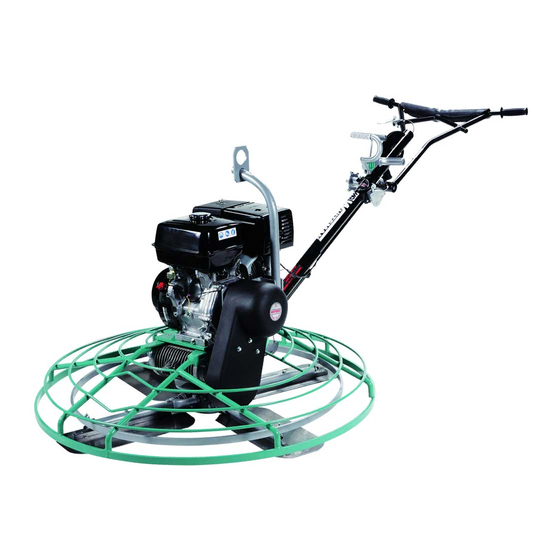
MULTIQUIP Whiteman series Operation Manual
Convertible edging walk-behind trowel (honda gx160 gasoline engine)
Hide thumbs
Also See for Whiteman series:
- Manual (100 pages) ,
- Operation and parts manual (82 pages) ,
- Operation manual (80 pages)
Table of Contents
Advertisement
Quick Links
Advertisement
Table of Contents
Troubleshooting

Related Manuals for MULTIQUIP Whiteman series


Summary of Contents for MULTIQUIP Whiteman series
- Page 1 OPERATION MANUAL SERIES MODEL J3036H55 CONVERTIBLE EDGING WALK-BEHIND TROWEL (HONDA GX160 GASOLINE ENGINE) Revision #0 (06/27/18) To find the latest revision of this publication, visit our website at: www.multiquip.com THIS MANUAL MUST ACCOMPANY THE EQUIPMENT AT ALL TIMES. PN: 13412...
-
Page 2: Proposition 65 Warning
PROPOSITION 65 WARNING Engine exhaust some its constituents, and some dust created by power sanding, sawing, grinding, drilling and other construction activities contains chemicals known to the State of California to cause cancer, birth defects and other reproductive harm. Some examples of these chemicals are: Lead from lead-based paints. -
Page 3: Silicosis/Respiratory Warnings
SILICOSIS/RESPIRATORY WARNINGS WARNING WARNING SILICOSIS WARNING RESPIRATORY HAZARDS Grinding/cutting/drilling of masonry, concrete, metal and Grinding/cutting/drilling of masonry, concrete, metal and other materials with silica in their composition may give other materials can generate dust, mists and fumes off dust or mists containing crystalline silica. Silica is a containing chemicals known to cause serious or fatal basic component of sand, quartz, brick clay, granite and injury or illness, such as respiratory disease, cancer,... -
Page 4: Table Of Contents
TABLE OF CONTENTS J3036H55 Convertible Edging Walk-Behind Trowel Proposition 65 Warning ........... 2 Silicosis/Respiratory Warnings ........ 3 Table Of Contents ............ 4 Training Checklist ............ 5 Daily Pre-Operation Checklist ......... 6 Safety Information ..........7–12 Lifting And Transporting ......... 13 Specifications ............ -
Page 5: Training Checklist
TRAINING CHECKLIST Training Checklist Description Date Read operation manual completely. Machine layout, location of components, checking of engine oil level. Fuel system, refueling procedure. Operation of controls (machine not running). Safety controls, safety stop switch operation. Emergency stop procedures. Startup of machine, engine choke. Maintaining a hover. -
Page 6: Daily Pre-Operation Checklist
DAILY PRE-OPERATION CHECKLIST Daily Pre-Operation Checklist Engine oil level Gearbox oil level Condition of blades Blade pitch operation Safety stop switch operation PAGE 6 — J3036H55 WALK-BEHIND TROWEL • OPERATION MANUAL — REV. #0 (06/27/18) -
Page 7: Safety Information
SAFETY INFORMATION DO NOT operate or service the equipment before reading Potential hazards associated with the operation of this equipment will be referenced with hazard symbols which the entire manual. Safety precautions should be followed at all times when operating this equipment. may appear throughout this manual in conjunction with Failure to read and understand the safety safety messages. - Page 8 SAFETY INFORMATION SAFETY DECALS GENERAL SAFETY Safety decals associated with the operation of this CAUTION equipment are defi ned below: „ NEVER operate this equipment without proper protective clothing, shatterproof glasses, respiratory protection, hearing protection, steel-toed boots and other protective DANGER devices required by the job or city and state regulations.
- Page 9 „ NEVER use accessories or attachments that are not restricted. If the air fl ow is recommended by Multiquip for this equipment. Damage restricted it will cause injury to the equipment and/or injury to the user may result.
- Page 10 SAFETY INFORMATION ENGINE SAFETY CAUTION „ NEVER stand on the trowel during operation. WARNING „ NEVER lubricate components or attempt service on a „ DO NOT place hands or fingers inside the engine running machine. compartment while the engine is running. „...
- Page 11 SAFETY INFORMATION FUEL SAFETY TRANSPORTING SAFETY DANGER WARNING „ DO NOT add fuel to the equipment if it is placed inside „ NEVER allow any person or animal a truck bed with plastic liner. The possibility exists of to stand underneath the equipment explosion or fi re due to static electricity.
- Page 12 SAFETY INFORMATION ENVIRONMENTAL SAFETY/DECOMMISSIONING EMISSIONS INFORMATION NOTICE NOTICE Decommissioning is a controlled process used to safely The gasoline engine used in this equipment has been retire a piece of equipment that is no longer serviceable. designed to reduce harmful levels of carbon monoxide If the equipment poses an unacceptable and unrepairable (CO), hydrocarbons (HC), and nitrogen oxides (NOx) safety risk due to wear or damage or is no longer cost...
-
Page 13: Lifting And Transporting
LIFTING AND TRANSPORTING LIFTING THE TROWEL Lifting Bail The lifting bail provides an optimal lift point for the trowel. WARNING When lifting the trowel onto a concrete slab, attach a chain Extra care should be taken when lifting the trowel. or rope to the lifting bail. -
Page 14: Specifications
SPECIFICATIONS Table 1. J3036H55 Trowel Specifications Table 2. Honda Engine Specifications Number of Blades Model Honda GX160UT2QX2 Ring Diameter 30 in./36 in. (762 mm/914 mm) Air-cooled, 4-stroke, single-cylinder, Type gasoline engine Rotor Speed 60–115 rpm Bore × Stroke 2.7 in. × 1.8 in. (68 mm × 45 mm) Path Width 30 in./36 in. -
Page 15: Dimensions
DIMENSIONS SIDE VIEW STANDARD HANDLE SHOWN TOP VIEW Figure 2. J3036H55 Dimensions Table 4. J3036H55 Dimensions (A) Height (Handle) 41 in. (1,044 mm) (B) Height (Lifting Bail) 28 in. (714 mm) (C) Width (Outer Ring Diameter) 36 in. (914 mm) (D) Width (Inner Ring Diameter) 30 in. -
Page 16: General Information
If the original manual is lost or damaged, please contact your nearest Multiquip dealer TRAINING for a replacement. For proper training, please use the Training Checklist Drive System form located in the front of this manual. - Page 17 NOTES J3036H55 WALK-BEHIND TROWEL • OPERATION MANUAL — REV. #0 (06/27/18) — PAGE 17...
-
Page 18: Components (Trowel)
COMPONENTS (TROWEL) Figure 3. Trowel Components PAGE 18 — J3036H55 WALK-BEHIND TROWEL • OPERATION MANUAL — REV. #0 (06/27/18) - Page 19 (i.e. the operator releases the squeezing the trigger. Push the T-handle forward to pitch handlebar during operation). the blades flat (no pitch). Contact Multiquip unit sales to purchase this option. 11. V-Belt Cover — Remove this cover to gain access to the V-belt.
-
Page 20: Components (Engine)
COMPONENTS (ENGINE) CAUTION DO NOT disable or disconnect the engine ON/OFF switch. It is provided for operator safety. Injury may result if it is disabled, disconnected, or improperly maintained. 5. Recoil Starter — Manual starting mechanism. Pull the starter grip slowly until resistance is felt, then pull briskly and smoothly to start the engine. -
Page 21: Setup
This section provides general instructions on how to install these components. For detailed handle 1. To place the folding upper handle in the operational assembly intructions, contact Multiquip and request position, turn the star wheel counterclockwise to Instruction Sheet P/N 20485. - Page 22 If additional handlebar adjustment is desired, a trowel ADJUSTER CABLE handle wedge kit (P/N 2576) can be purchased from your Multiquip dealer. The wedges are placed between the handle and the gearbox, which will move your handle operating SWIVEL STOP position approximately 3 inches (76 mm) up or down.
- Page 23 SETUP Blade Pitch Cable Installation 9. Route the throttle wire approximately 1/2 inch past the cable retaining screw (Figure 10). Tighten the cable 1. For trowels equipped with a standard handle (SXH), retaining screw to secure the throttle wire. turn the star wheel counterclockwise to release 10.
- Page 24 SETUP Pre-Load Adjustment (Quick Pitch™ Handle Only) 3. Remove brass set nut #1 from the end of the blade pitch cable (Figure 14). CAUTION The Quick Pitch™ handle is spring-loaded. Personal injury or damage can result from improper handling, BLADE installation, or adjustment.
- Page 25 SETUP 36-Inch to 30-Inch Guard Ring Conversion 2. Remove the twelve M8-1.25 × 25 mm HHC screws and M8-1.25 nyloc nuts securing the 36" guard-bumper 1. Remove and retain the four 5/16-18 × 1-1/4" ring assembly to the 30" guard ring (Figure 18). Retain HHFS screws and four 5/16-18 ×...
- Page 26 SETUP 4. The inner surface of the 30" bumper is marked with 7. Secure four 8" × 10.5" trowel blades to the spider the letter ‘T.’ Orient the 30" bumper with the ‘T’ upward. assembly (Figure 20) with the four 5/16-18 × 1-1/4" Orient the 30"...
- Page 27 SETUP 30-Inch to 36-Inch Guard Ring Conversion 2. Remove the six M8-1.25 × 25 mm HHC screws, six M8-1.25 × 45 mm HHC screws, and twelve M8-1.25 1. Remove and retain the four 5/16-18 × 1-1/4" nyloc nuts securing the 30" bumper ring to the 30" HHFS screws and four 5/16-18 ×...
- Page 28 SETUP 4. Secure the 36-inch guard-bumper ring assembly to the 5. Secure four 8" × 14" trowel blades to the spider 30-inch guard ring with the twelve M8-1.25 × 25 mm assembly with four 5/16-18 × 1-1/4" HHFS screws and HHC screws and M8-1.25 nyloc nuts (Figure 23).
- Page 29 SETUP Float Disc Installation (Optional) Float discs, or pans, attach to the trowel blades and allow the trowel to ‘float’ on wet concrete. The disc design facilitates early floating and easy movement from wet to dry areas. Float discs are also very effective at embedding large aggregates and surface hardeners.
-
Page 30: Inspection
INSPECTION ENGINE OIL FUEL 1. Place the trowel on secure, level ground with the Remove the fuel filler cap and inspect the fuel level in engine OFF. the tank. If fuel is low, replenish with 86 octane or higher unleaded gasoline. 2. - Page 31 INSPECTION V-BELT BLADES 1. Inspect the V-belt (Figure 29) to determine if it is frayed, Inspect the trowel blades for wear or damage (Figure 31). If peeling, full of tiny cracks, has pieces of rubber missing, one blade is worn out while the others look new, there could be a blade pitch problem.
-
Page 32: Operation
OPERATION This section is intended to assist the operator with the initial 2. Place the engine ON/OFF switch in the ON position startup of the walk-behind trowel. It is extremely important (Figure 34). that this section be read carefully before attempting to use the trowel in the field. - Page 33 OPERATION CENTRIFUGAL SAFETY STOP SWITCH TEST 5. If starting a warm engine, place the choke lever in the OPEN position (Figure 37). CAUTION Test the centrifugal safety stop switch every time the engine is started. NEVER operate the trowel without making sure the switch is operational.
- Page 34 OPERATION TO BEGIN TROWELING Quick Pitch™ Handle Place the throttle lever (Figure 41) in the RUN position. To pitch the blades upward with the Quick Pitch™ handle (Figure 43), pull the T-handle backward while squeezing the trigger lock. Push the T-handle forward to pitch the blades flat (no pitch).
- Page 35 OPERATION MANEUVERING THE TROWEL 1. Stand in the operator’s position behind the handle. With 3. Continue to practice maneuvering the trowel as if secure footing and a firm grasp on the handle, slowly finishing a slab of concrete. Practice edging and increase the engine speed until the desired blade speed covering a large area.
- Page 36 OPERATION STOPPING THE TROWEL 4. Place the fuel valve lever in the CLOSED position (Figure 48). 1. Return the throttle lever to the IDLE position (Figure 45) and let the engine run for three minutes at low speed. IDLE FUEL VALVE LEVER THROTTLE LEVER...
-
Page 37: Options
T-handle. Refer to the Operation section of equipped with a star wheel for blade pitch adjustment. this manual for more information. Please contact Multiquip Refer to the Operation section of this manual for unit sales to order this option. - Page 38 If replacement blades are needed, refer to the parts manual provided with your trowel for part numbers, and order from Figure 53. Clip-On Float Blade your Multiquip parts dealer or importer. Float Discs (Optional) Combination Blades (Standard) Float discs, or pans (Figure 54), attach to the spider This trowel is equipped with combination blades (Figure 51) assembly and allow the trowel to float on wet concrete.
-
Page 39: Maintenance
MAINTENANCE Table 6. Engine Maintenance Schedule Before Every 6 Every 2 Description First Month Every Year Operation Each Months or Years or or 20 Hrs. or 300 Hrs. 100 Hrs. 500 Hrs. Check Engine Oil Change Check Air Cleaner Clean X (1) Change X ( * ) - Page 40 MAINTENANCE ENGINE MAINTENANCE General maintenance practices are crucial to the performance and longevity of your trowel. This equipment Inspect the engine daily for cleanliness, oil or fuel leakage, requires routine cleaning, lubrication, and inspection of and loose fasteners. components for wear or damage. Air Cleaner Refer to Table 6 and Table 7 to schedule engine and trowel maintenance.
- Page 41 MAINTENANCE Spark Plug 3. Clean the foam element in warm, soapy water or a nonflammable solvent. Rinse and dry thoroughly. Dip 1. Remove the spark plug (Figure 58) and clean it with a the element in clean engine oil and completely squeeze wire brush if it is to be reused.
- Page 42 MAINTENANCE 3. Replace the V-belt immediately if any of the above wear 2. Remove and retain the 4 mm screw securing the spark conditions are observed. arrester to the muffler, and remove the spark arrester (Figure 61). Fuel Strainer 3. Carefully remove carbon deposits from the spark 1.
- Page 43 MAINTENANCE TROWEL MAINTENANCE 3. Lubricate the Zerk grease fitting with 1 to 1½ shots of multipurpose grade grease. DO NOT overgrease. Clean the trowel daily. Remove all dust and slurry Replace the Zerk fitting cap when finished. buildup. Make sure lubrication is performed after any 4.
- Page 44 MAINTENANCE Once it has been determined that blade pitch adjustment PITCH ADJUSTMENT is required, do the following: BOLT LOWER WEAR PLATE 1. Place the trowel on a flat, level surface, with blocks under the main guard ring for support. Any uneven spots in the floor or debris under the trowel blades will cause an incorrect perception of adjustment.
- Page 45 MAINTENANCE Blade Replacement Trowel Arm Removal It is recommended to replace all of the trowel blades at the 1. Each trowel arm is held in place at the spider plate same time. If only one or some of the blades are changed, by a Zerk grease fitting (hex head bolt) and a roll pin.
- Page 46 MAINTENANCE 1. Place the trowel arm on a thick steel plate, granite slab, TROWEL ARM TROWEL FIXTURE or any other surface which is true and flat (Figure 71). FIXTURE (PLACED IN ADJUSTMENT FIXTURE CHANNEL) LEVER TROWEL ARM FLAT TEST BOLT SURFACE SHIM DISTANCE = .010 in.
- Page 47 MAINTENANCE REASSEMBLY LONG-TERM STORAGE 1. Clean the wear plates and thrust collar, and examine Perform the following procedure when storing the trowel the entire spider assembly. Use a wire brush to remove for more than 30 days. any concrete or rust buildup. Replace any spider „...
-
Page 48: Troubleshooting (Engine)
TROUBLESHOOTING (ENGINE) Troubleshooting (Engine) Symptom Possible Problem Solution Spark plug bridging? Check gap, insulation or replace spark plug. Carbon deposit on spark plug? Clean or replace spark plug. Short circuit due to defi cient spark plug Check spark plug insulation, replace if worn. insulation? Improper spark plug gap? Set to proper gap. - Page 49 TROUBLESHOOTING (ENGINE) Troubleshooting (Engine) - continued Symptom Possible Problem Solution Air cleaner dirty? Clean or replace air cleaner. Improper level in carburetor? Check fl oat adjustment, rebuild carburetor. Weak in power, compression is proper and does not misfi re. Defective spark plug? Clean or replace spark plug.
-
Page 50: Troubleshooting (Trowel)
TROUBLESHOOTING (TROWEL) Troubleshooting (Walk-Behind Trowel) Symptom Possible Problem Solution Engine ON/OFF Switch in "OFF" position Make sure that the Engine ON/OFF Switch is ON or malfunctioning? or replace switch if necessary. Centrifugal ON/OFF Switch in "OFF" Place centrifugal stop switch in "ON" position. position or malfunctioning? Check wiring. - Page 51 TROUBLESHOOTING (TROWEL) Troubleshooting (Walk-Behind Trowel) - continued Symptom Possible Problem Solution The main output shaft of the gearbox assembly should be checked for straightness. Main shaft? The main shaft must run straight and cannot be more than 0.003"" (0.08 mm) out of round at the spider attachment point.
-
Page 52: Wiring Diagram
WIRING DIAGRAM CENTRIFUGAL STOP SWITCH OIL LEVEL OIL ALERT ENGINE STOP UNIT IGNITION SPARK SWITCH UNIT SWITCH COIL PLUG TRANSISTORIZED IGNITION UNIT OIL LEVEL INDICATOR CHASSIS GROUND PAGE 52 — J3036H55 WALK-BEHIND TROWEL • OPERATION MANUAL — REV. #0 (06/27/18) - Page 53 NOTES J3036H55 WALK-BEHIND TROWEL • OPERATION MANUAL — REV. #0 (06/27/18) — PAGE 53...
- Page 54 © COPYRIGHT 2018, MULTIQUIP INC. Multiquip Inc , the MQ logo and the Whiteman logo are registered trademarks of Multiquip Inc. and may not be used, reproduced, or altered without written permission. All other trademarks are the property of their respective owners and used with permission.